Networking and Communications
Communication Protocols
For this week assignment we have to design, build, and connect wired or wireless node(s) with network or bus addresses. Thus, I started with a small investigation about the different types of protocols that exists in the electronics environment. Beforehand I knew the different protocols that can be used between microcontroller but I wanted to write down the most common which are the UART, the SPI and the I2C protocols.
- UART:
- SPI:
- I2C:
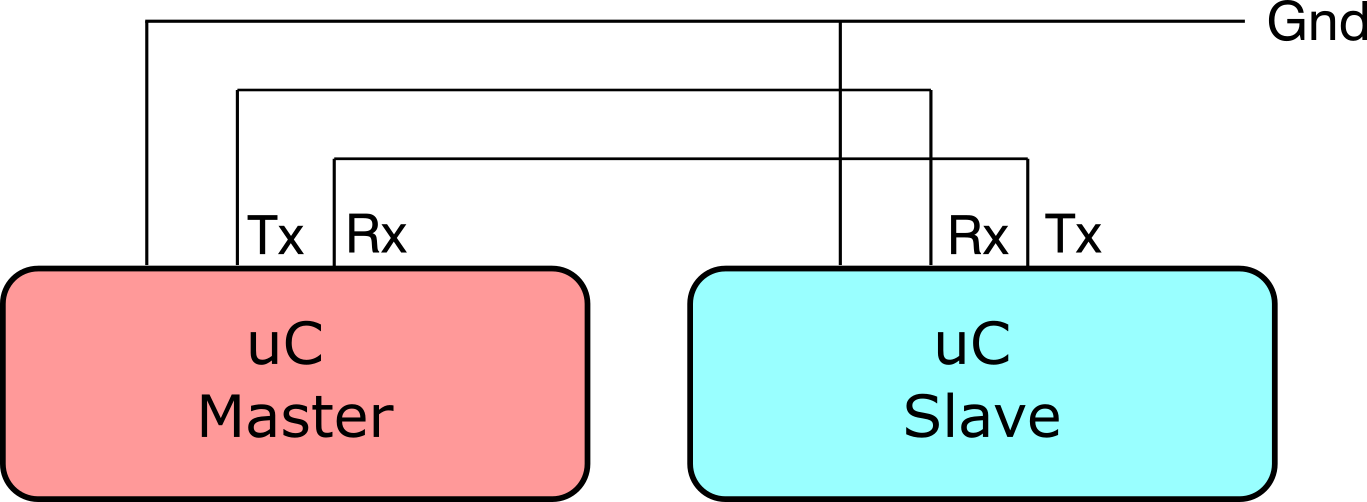
The Universal asynchronous receiver-transmitter (UART) is one of the most used protocols. It uses a single data line to transmit and another to receive data. This protocol can be used at 3.3V or 5V and the transmission speed must be fixed before the compilation.
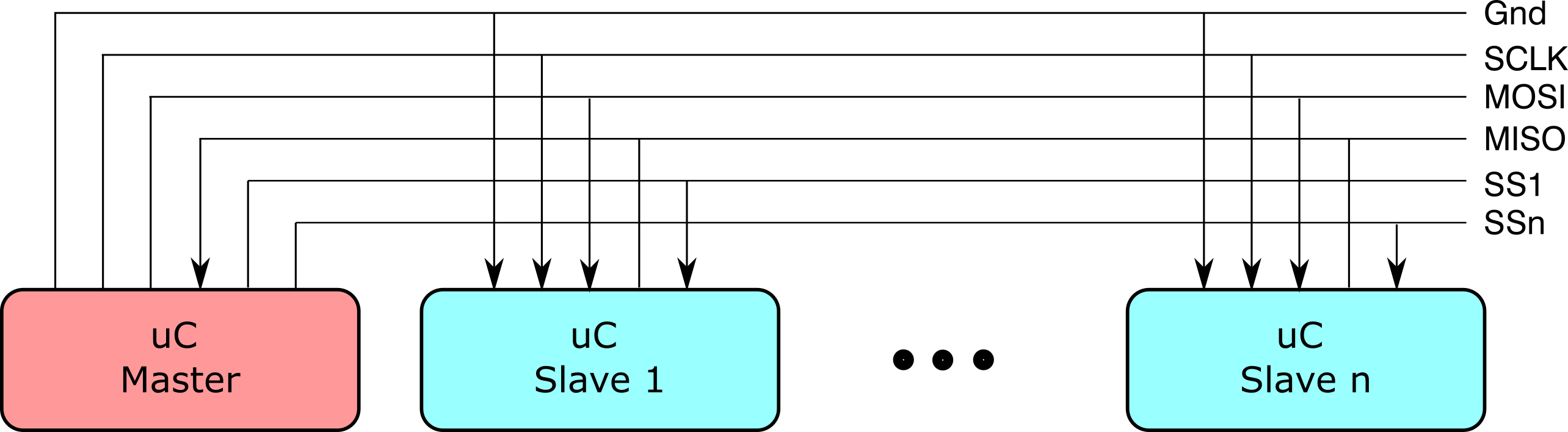
The Serial Peripherial Interface (SPI) protocol is another simple serial protocol. A master sends the clock signal, and after each clock pulse it sends a bit to the slave and receives a bit from it. The signal names are SCK for the clock, MOSI for the Master Out Slave In, and MISO for the Master In Slave Out. To control more than one salve is neccesary to use one Slave Selection pin for each new devices.
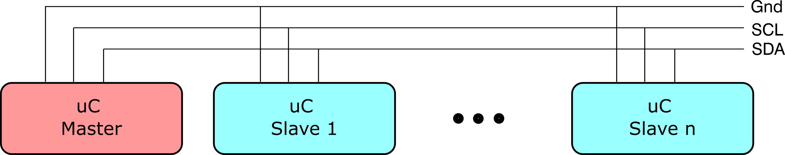
The Inter-integrated Circuti (I2C) prtocol is a synchronous protocol that only uses two wires besides the power supply, clock (SCL) and data (SDA). This means that the master and the slave send data over the same wire, which is controlled by the master through a clock signal. The I2C does not have a slave selection pin but it has an address. The first byte sent by the master is composed of 7 bits for the address(thus, it can communicate with up tu 127 devices).
The following table is a comparative table with the most important characteristics between these three protocols
| Characteristic | UART | SPI | I2C |
|---|---|---|---|
| Pins | Tx for data transmission and Rx for data reception | SCK for clock, MOSI for Maste Out Slave In, MISO for Master In Slave Out and SS for Slave Selector | SDA for data and SCL for clock |
| Data Speed | Maximum between 230 Kbps and 460 Kbps | Normally between 10 Mbps and 20 Mbps | Maximum between 1 Mbps and 3.4 Mbps |
| Communication type | Asynchronous | Synchronous | Synchronous |
| No. of master | Asynchronous | Synchronous | Synchronous |
| Clock | Internal clock in each device | Commom clock signal between master and slaves | Commom clock signal between master and slaves |
Proposed Network
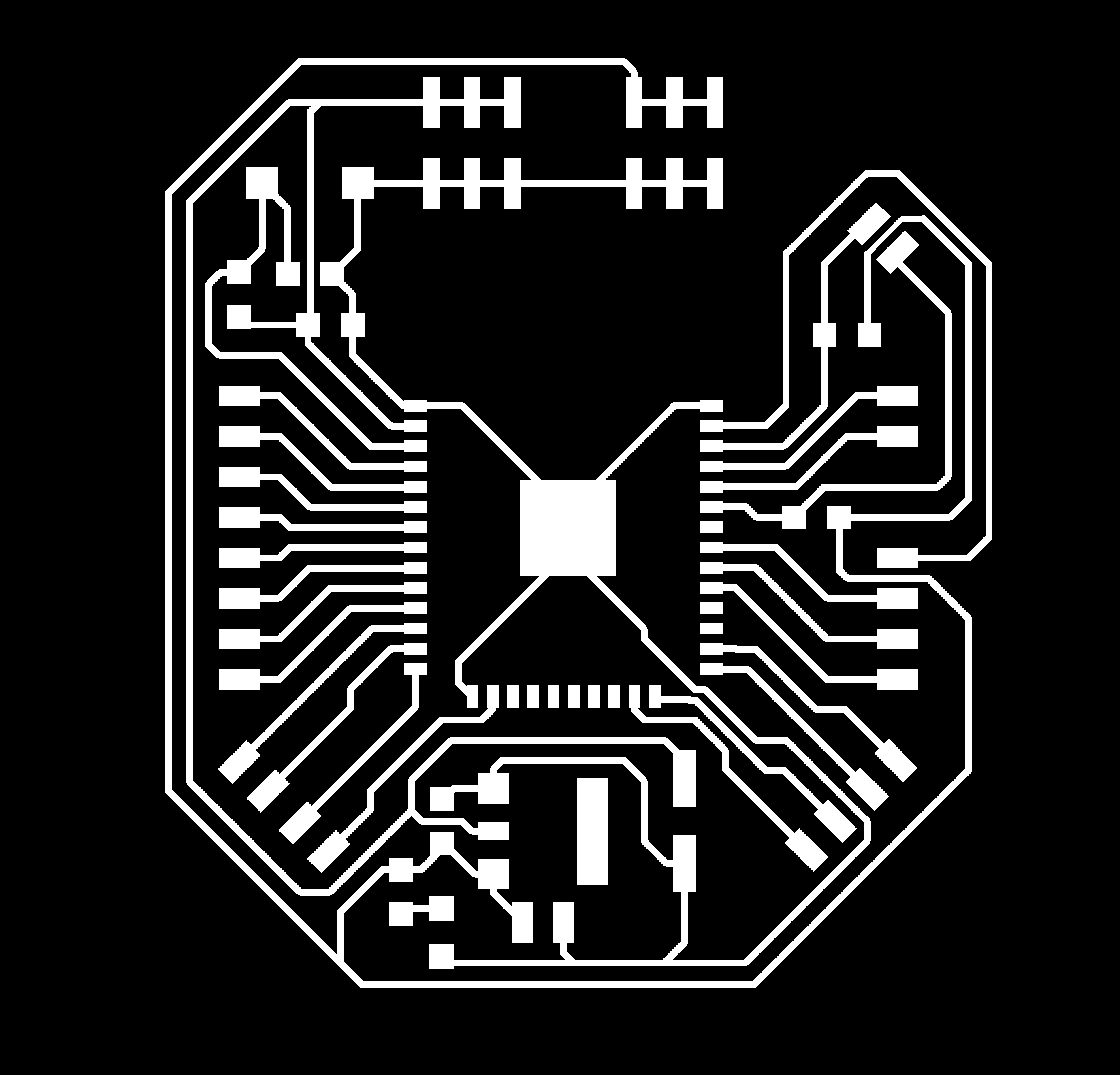
The objective of this week assignment is to create an I2C network between the different inputs and outputs that I already created in the past weeks aling with a UART communication between the ESP32 and the computer. The main idea is that the computer will program and communicate with the ESP32 thorugh UART protocol and depending on the received value the ESP32 will communicate with the MPU6050, the ATtiny45 or the PCA9685 through I2C. Before I started with the wiring of this network, I decided to create an electrical diagram that shows network between these protocols and these devices
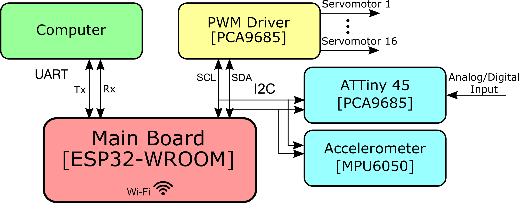
Therefore, I will use the input board, the output board and the main board that were created in the previous weeks. I explain the main function of each board in order to remember a little bit about the function of each board
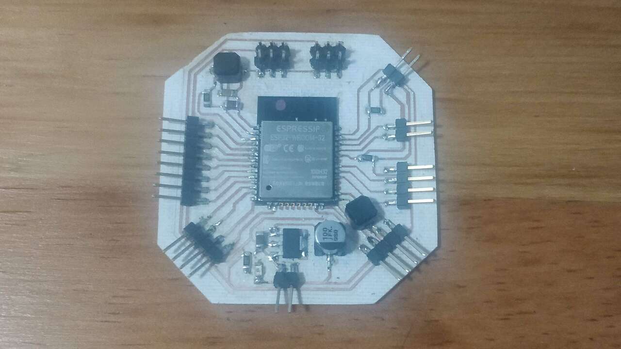
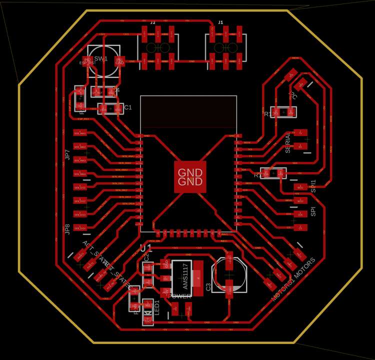
The first board is an ESP32-WROOM which is a powerfull micrcontroller with multiple communication protocol and multiple GPIO's. Most importantly it has Wi-Fi communication which I'm planning to use for my final project. This board has two push button, one to reset the board and the other one to program the ESP32. It also has UART, I2C and SPI pins to increase the communication that it can have with the outside world. Finally, it has multiple GPIO and multiple power pins at 5V and 3.3 V
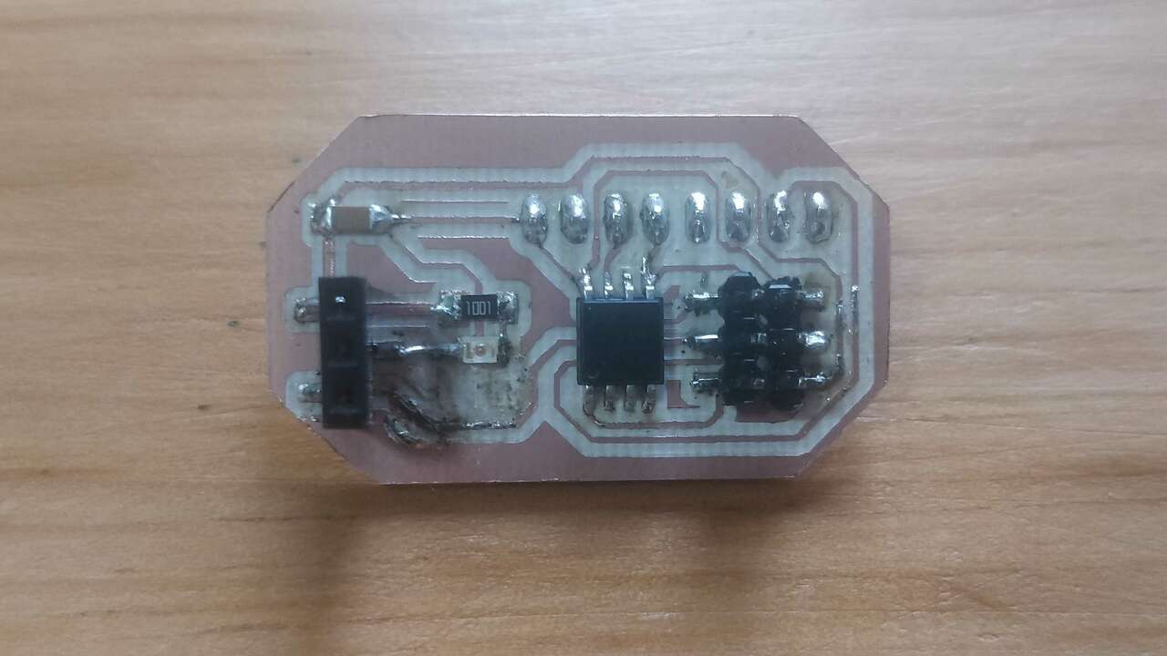
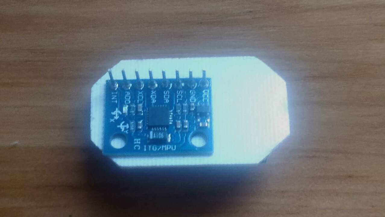
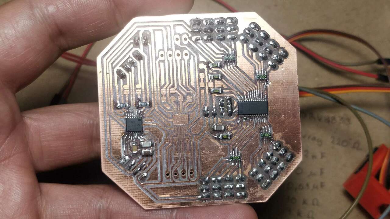
The second board is a board that contains two devices, a MPU6050 which is an accelerometer of 6 axes and an ATtiny45 which is programmed to received a digital input from an external sensor and it sends the sensor state through I2C
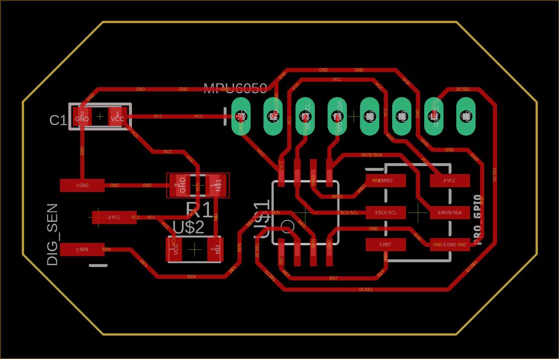
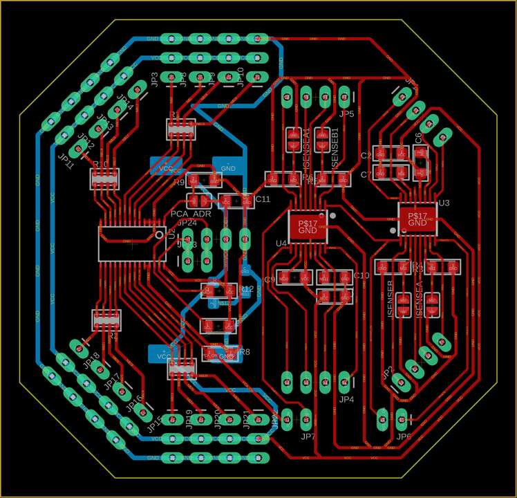
The third board is an really complex board with many functionalities, it has a single PCA9685 which is a PWM generatos and it allows us to control up to 16 servomotor at a time. It also has two DRV8833 which are dual bridges that can handle up to 1.5 A every single bridge. This board has multiple pins to directly connect the required servomotors or motors.
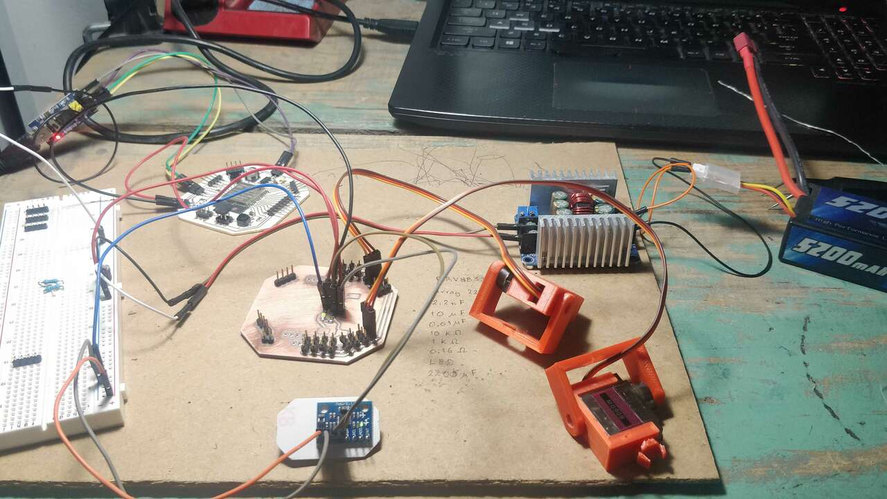
Now it is time to start wiring the network between the previous board and the figure below shows the final connection betwen devices.
Programming the main board
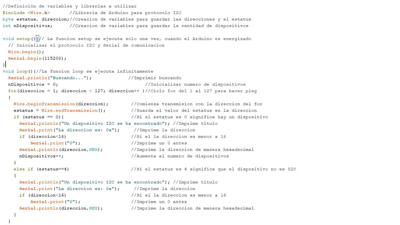
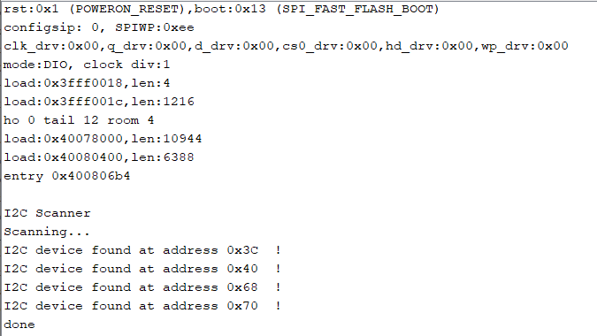
Before try to send values directly to my board, I verified that the I2C communication was correct using the code of last week assignment. The following picture shows the serial monitor and the I2C devices that the main board detects. It is important to note that the 0x40 and the 0x70 is the same device (PCA9685) while the 0x68 is the MPU6050 and the 0x3C is the ATtiny45.
After knowing that the I2C network is working well, I started the code that I used to control the boards through UART and the computer. I did not have many troubles creating the code since I already have the codes of the previous boards. Nevertheless, I created functions to display the value of the sensors and I also mixed both codes with the addition of some conditional to detect the user input in the serial monitor. The first try did not work well because the initial message was displayed multiple times until the user entered a string. Thus, I searched in internet about a way to avoid that problems and wait to the user input. I found that the follwing instructions allows you to do that:
		 //Wait for an answer
while (Serial.available()==0) {  }
if(Serial.available()){
//Assign the written value to the readwrite variable
readwrite = Serial.readStringUntil('\n');
}
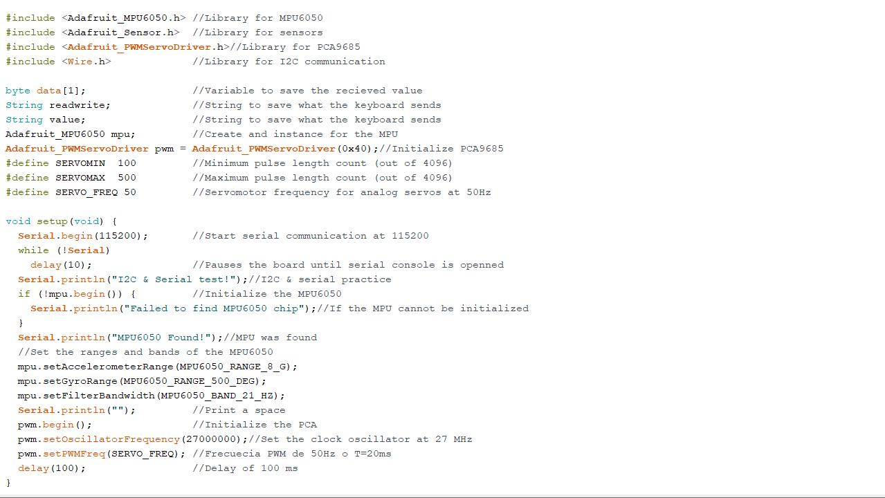
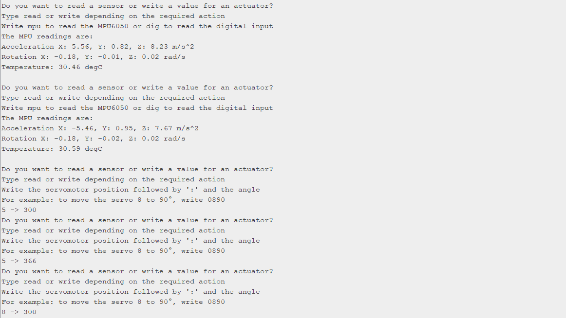
Once I figure that out, I was able to wait for the user input and analyze the given input to read a sensor or actuate a servomotor. Thus, the picture below shows part of the final code that I used to control the input/output boards with the computer trough the ESP32 and UART.
The video above shows how the board was programmed with the previous code to control the whole I2C network from the computer through UART and the ESP32
The following picture shows the serial monitor that was used in the previous video where can be seen with more detail the interaction between the user computer and the I2C network
Files created
Useful Resources