Input Devices
Probing Analog and Digital Inputs
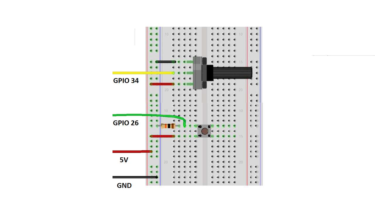
Before I started to program or design my new board for the input signals. I decided to created something similar to an oscilloscope in Arduino to show how the digital and analog signals are displayed in measuring device like this. So, first I use a push button with a pull-down resistor to make sure we have a change between 0 logic and 1 logic. The following diagram shows the devices that I used along its wiring connection to the ESP32 board.
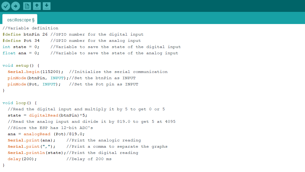
Once I completed the previous diagram, I created a code to read the analog and digital inputs which can be seen below:
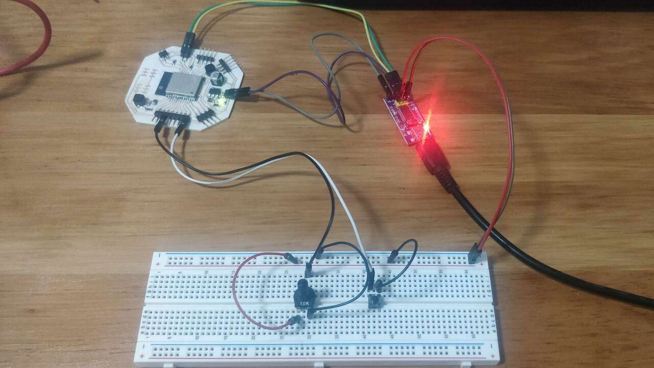
The next two pictures shows the connection between components and a plot of the signals that the ESP32 was reading. In order to acces to the plot option you have to go to Tools and select Serial Plotter instead of Serial Monitor.
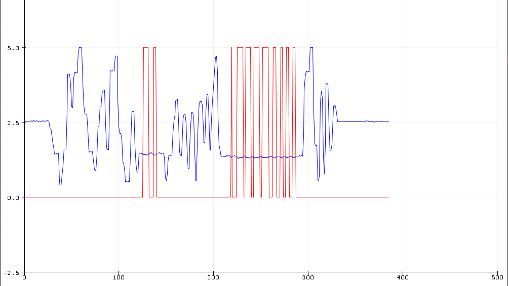
The video above shows how the Arduino serial plotter illustrates the different signals that are sent via serial to the computer
Accelerometer + Proximity Sensor
When I first desgined the main board for my final project, I did not know that type of sensor I might need. Nevertheless later on I figured it out. I wanted to use a proximity sensor and an accelerometer. The proximityy sensor is useful to avoid any posible obstacle that the robot can face when it is moving forward and the acceleromenter is very useful if you have an humanoid or any other configuration that requires the orientation and acceleration of the robot. Thus, I analized the pinout of these sensor to see what type of microcontroller I can use to control both or one sensor.
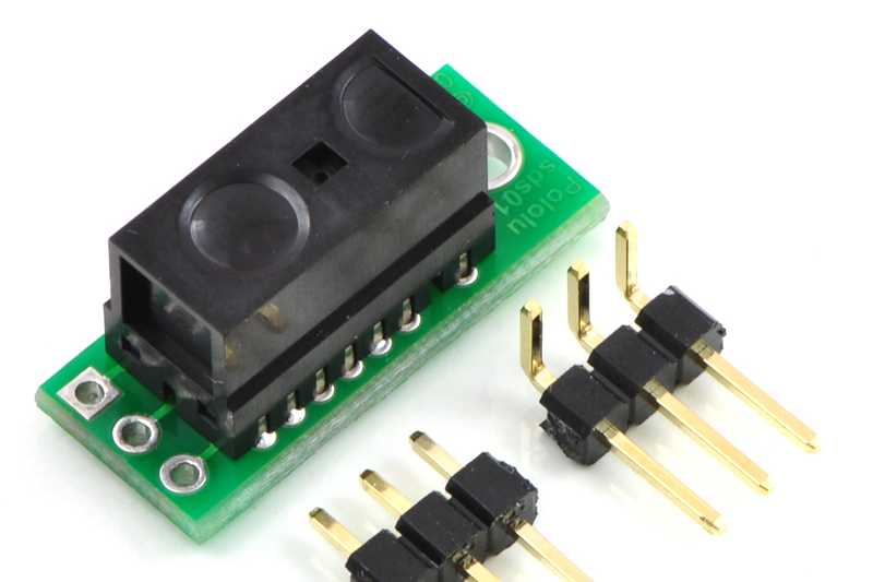
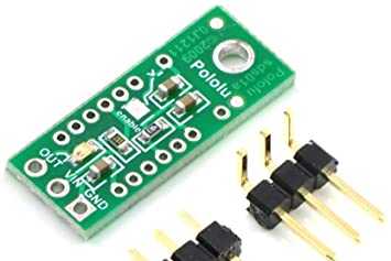
I already have a proximty sensor that is made by Pololu and it uses the GP2Y0D810Z0F which is a distance measuring unit of SHARP. This sensor is in a PCB an it has a digital input; The output has a value of 0V(GND) when the sensor detects an object between 2 to 10 cm, and it has a value of 5V on the contrary. The following pictures show the pinout of the sensor along its both sides:
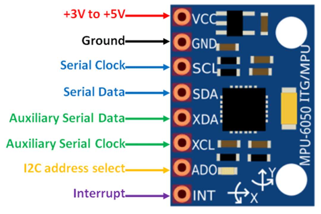
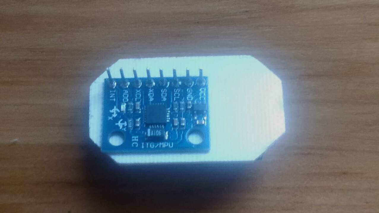
Now that we know the pinout of the proximity sensor, it is time to see the pinout of the Accelerometer. The selected accelerometer is the MPU6050 which has 9-axis MotionFusion by the on-chip Digital Motion Processor (DMP) and it also has a digital putput triple-axis accelerometer with a programable full range of ±2g, ±4g, ±8g and ±16g. The following picture shows the pinout of this sensor
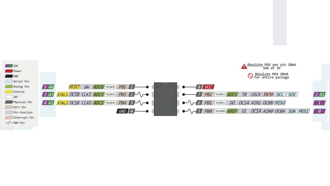
Once I knew the sensors I wanted to integrated into my new board, I proceed to find a microcontroller with I2C capabilities and at least two inputs/outputs (one for the digital ouput of the proximity sensor and another for the digital input of the MPU6050 to change its I2C adress). After reading a few datasheet, I found out that the ATtiny45 has enough pins to control the digital sensor and send its value through I2C like the MPU6050. The pinout of the ATtiny 45 is shown below.
Designing the board
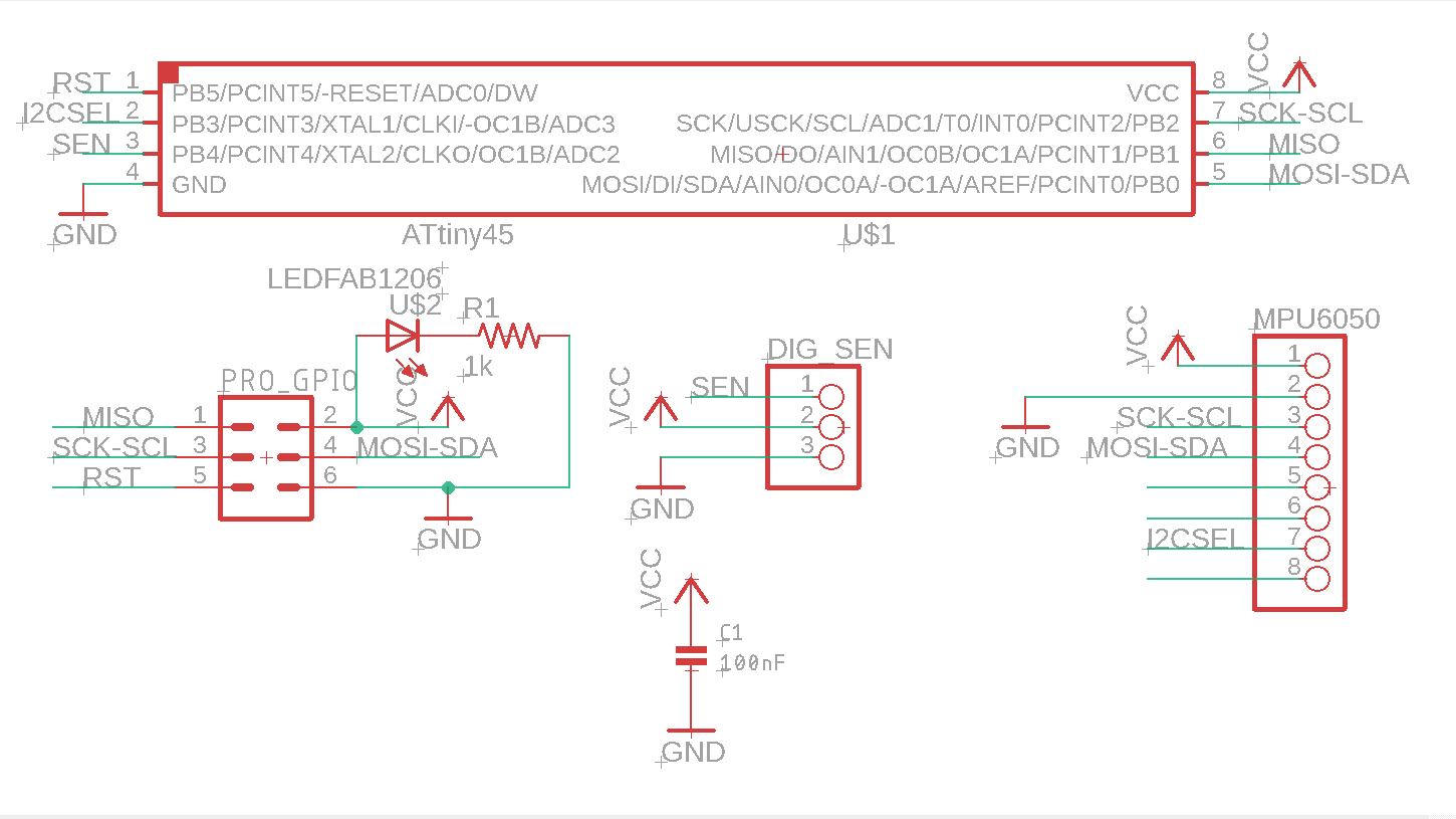
The following picture show the schematics of my new input board. It is important to note that the pins that I selected for the MPU6050 are pins with holes since I want to place the accelerometer at the back of the board to facilitate the initial orientation of the board. In case you want to know more about the design process using Eagle you can go to Electronic Design week
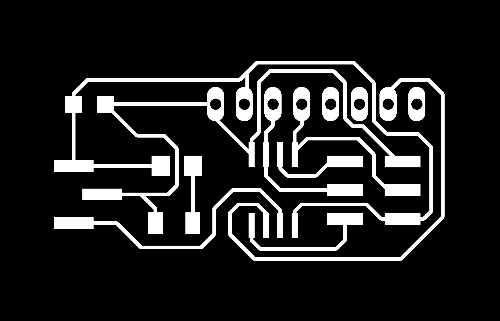
After the schematics was done, I proceed to wire all the components together. It was a little bit hard since I had to connect the ISP connector and both sensor to the ATtiny45. I spent almost an hour and I couldn't join all the pad without using another layer but I rememberd that I used the same microcontroller for my programmer so I went back to the board and copy the ISP connection to the microcontroller. After that changed was made the other pins where a way easier.
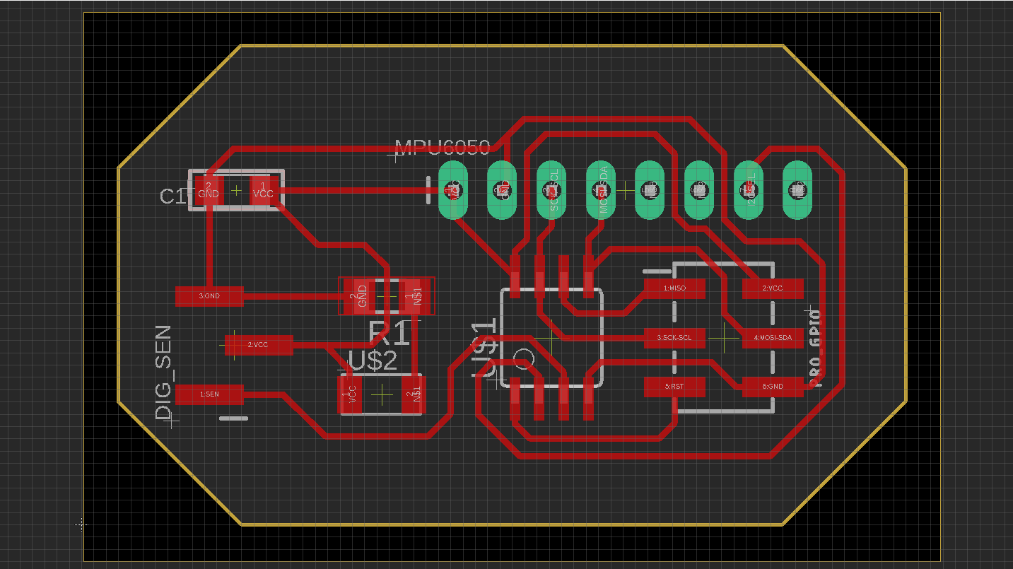
After the board was done, I saved the trace and outline pictures to create the required G-code in fab modules . The images that I used are presented above:

Creating the board
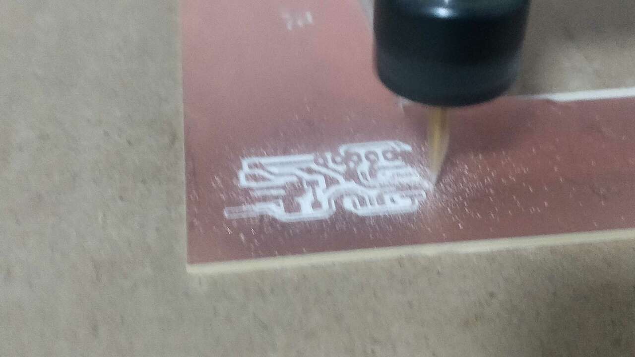
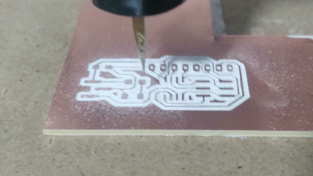
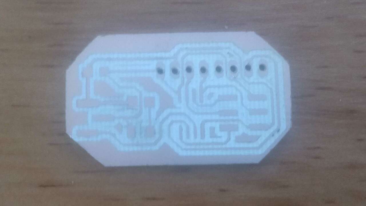
Using the G-code created in FabModules I sent my code to the Mini Router CNC 3018 PRO usign UGS and the same procedure that was used to machine my board shown in Electronic Production week. Thus, I machined my board and the next pictues shows the process of it.

The following table shows the bill of material to create this PCB.
| Quantity | Component | Model |
|---|---|---|
| 1 | Microcontroller | ATtiny45 |
| 1 | Proximity Sensor | GP2Y0D810Z0F |
| 1 | Accelerometer | MPU6050 |
| 1 | Ceramic Capacitor | 100nF |
| 2 | Resistor | 1k Ohm |
| 1 | LED | 1206 |
| 1 | Pin header | 2x3 for SMD |
| 1 | Pin header | 1x8 trough hole |
| 1 | Pin connector | 1x3 for SMD |
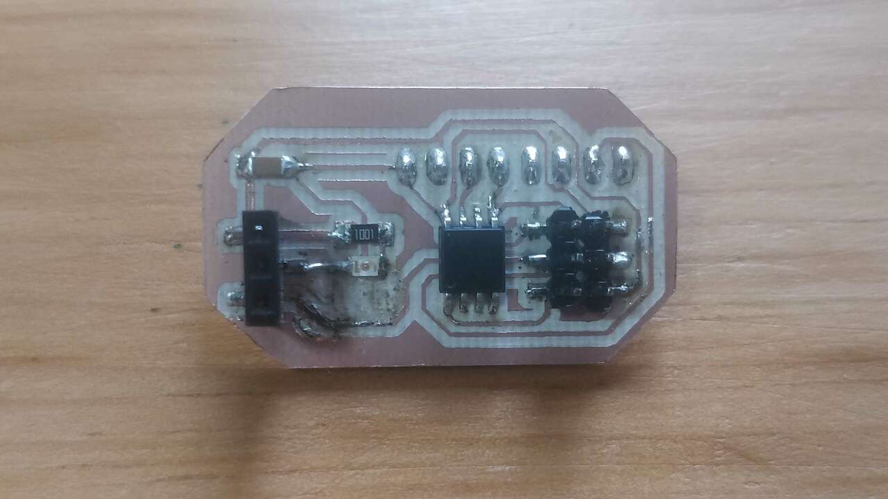
The following picture shows the required components and the board:

I was really happy to see the final board since it looked exactly as I imagened:
Programming the board
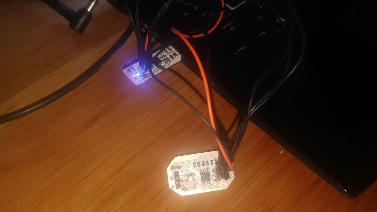
Before I tried to read the sensor or stablish the I2C communication, I decided to do a small test where an LED was turning on and off every second. So, I connected my ISP programmer to my computer and I opened the example called Blink in arduino. The following pictures show the code and the connection between programmer and the board.
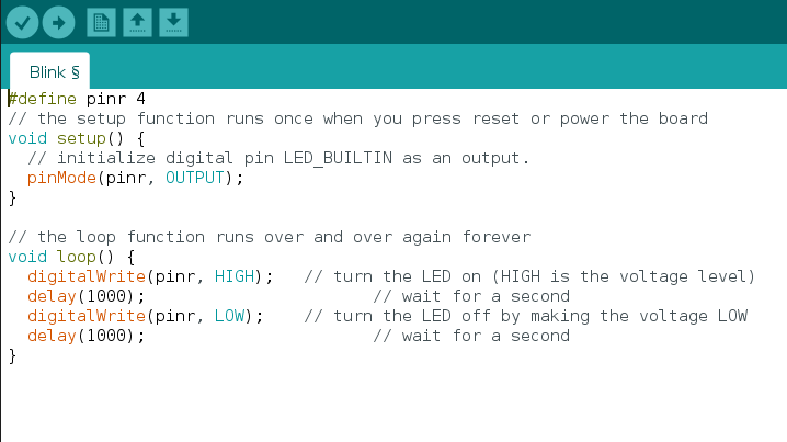
It is important to note that I changed the pin number because the example is for an Arduino Uno and not for the ATtiny45. Besides that change I had to add the ATtinny board to the Arduinoo IDE, because it does not have these microncontrollers by default. Thus, I click on File->Preferences->Additional Boards Manager URLs, I copied the followng link
https://raw.githubusercontent.com/damellis/attiny/ide-1.6.x-boards-manager/package_damellis_attiny_index.json
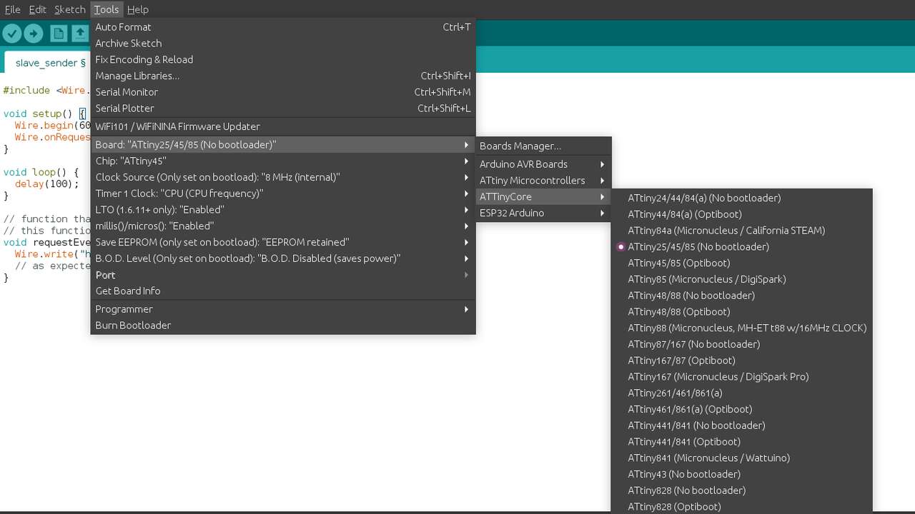
Later I click on Tools->Board->Board Manager and I look for the board manager called ATtinyCore by Spence Conde. Later, I clicked on install and I waited for arduino to be installed. When I clicked Close, I was able to see a new board manager under the board selection as the image below.
After the connection was done, I proceed to upload the code to the microcontroller and see if the LED was blinking. In the video above, we can appreciate how the microcontroller was programmed and the functioning of it.
To test the functionality of the sensor and the microcontroller, I created a code to detect when the sensor detects something and send the text "Here I'm". This code is shown below
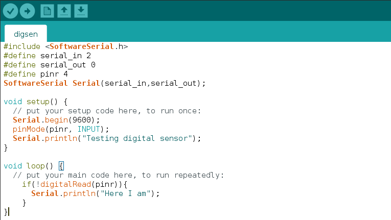
The following video shows how the microcontroller detects when the sensor sends the signal that something was detected.
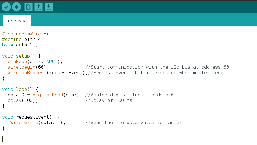
Now the difficult part has arrived. It is time to use the previous code and use the ATtiny as a sender slave which must read the digital input of the sensor and send the value of it. The following picture shows the code that I use to programm the ATtiny:
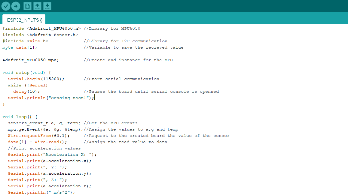
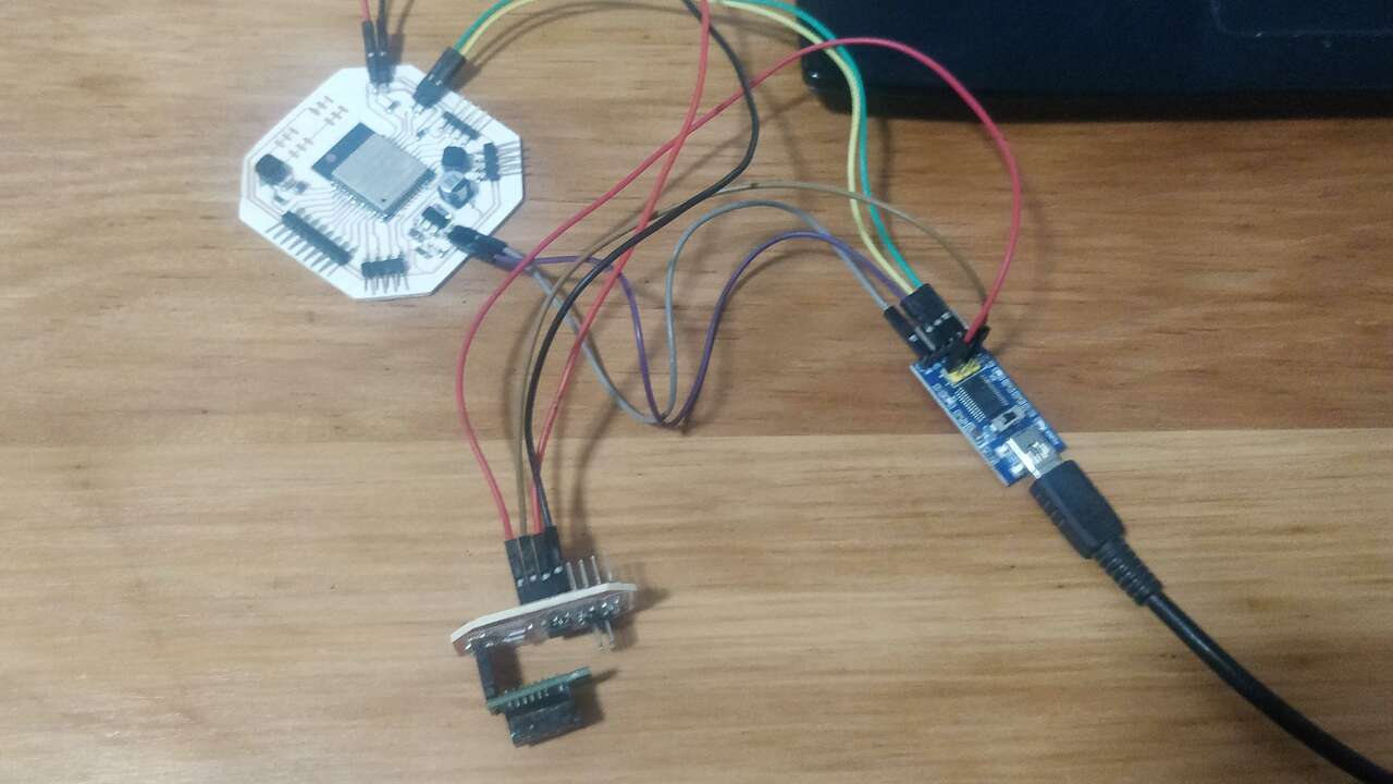
In order to test that the board is working as expected with the I2C communication, I used my ESP32 board for my final project to read the I2C devices (ATtiny and MPU) and show the read values in the serial monitor. So, I did the folliwng connection between components and I uploaded the following program to the ESP32:
Finally, the following video shows how the ESP detects both sensor, the accelerometer and the proximity sensor through I2C communicaction to the ATtiny and the MPU6050.
Files created
Useful Resources