Assignments
- Evaluate and select your desired 2D and 3D software
- Document processes used in modelling with 2D and 3D software.
- Model (raster, vector, 2D, 3D, render, animate, simulate, …) a possible final project, and post it on your class page.
Week 2

Figure 1. Changing saturation of the image.

Figure 2. Tracing over outline of the image.

Figure 3. Adding a new layer with white color.
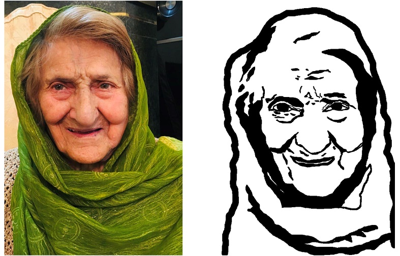
Figure 4. Original image vs proccessed image.
For this week, I decided to design a kinf of logo for my further activites during Fab Academy. First, I downloaded the logos of Fab Academy and Fab Lab Oulu which is my local fablab. Then, I openned Inkspace and from File->Import..., I uploaded the first logo.
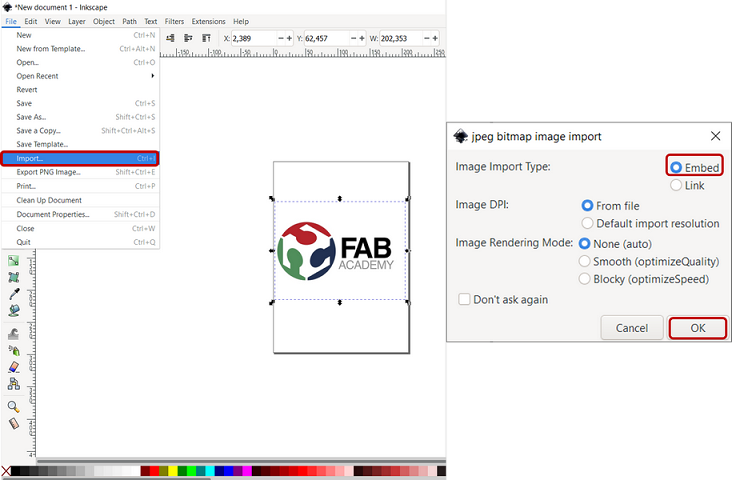
Figure 5. Importing a file in Inksapce
Then, from Path->Trace Bitmap..., you will see the three filter options available: Brightness Cutoff, Edge Detection and Color Quantization which I chose Brightness Cutoff . The "Brightness threshold" default was quite low and one part of the text was missing, so I had to increase it up to 0.890 to have the complete text with enough contrast. Then, press OK and you will see another layer created. I simply removed the original photo and kept the traced one for the rest.

Figure 6. Setting Trace bitmap in Inkspace
Then, I added a text from the tool on the left side of the toolbar (Figure 7). Then, from the right side, you can edit the font type, size or style.
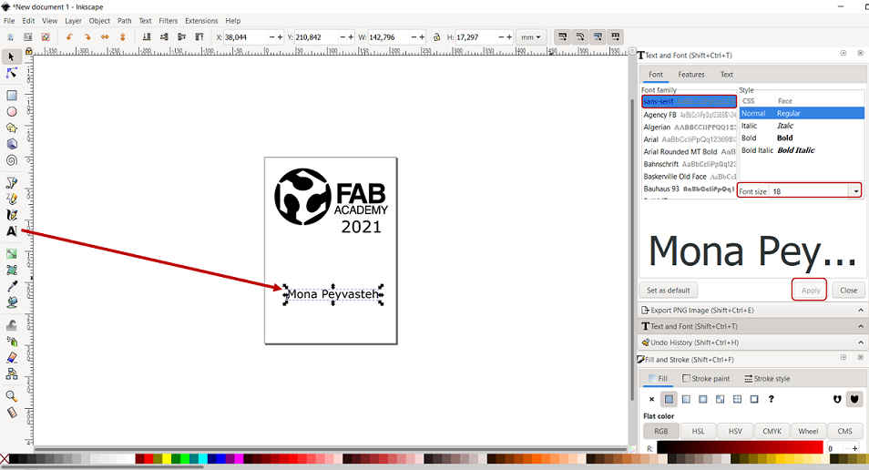
Figure 7. Setting Trace bitmap in Inkspace
To change both width and height by the same proportion, you can press the locker on the top toolbar (Figure 8)

Figure 8. When locked, change both width and height by the same proportion
Then, I imported another logo for Fab Lab Oulu and did the same process for trace bitmap. But befor that, I tried to crop part of the logo which made me falimiar with a new feature in Inkspace. To crop an image in Inkspace, I drew a rectangular around the part I was going to keep. Then, I selected both objects (the full logo+rectangle) by pressing Shift and then, I clicked Object->Clip->Set which will remove the area out side of the rectangle.
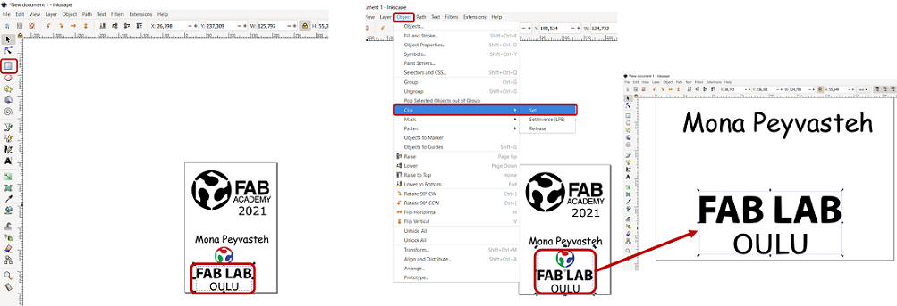
Figure 9. Crop process in Inkspace
Finally to make a frame, from the left bar, I drew an ellipse around the objects, then, to resize page to drawing, go to File->Document Properties->Resize page to drawing or selection.
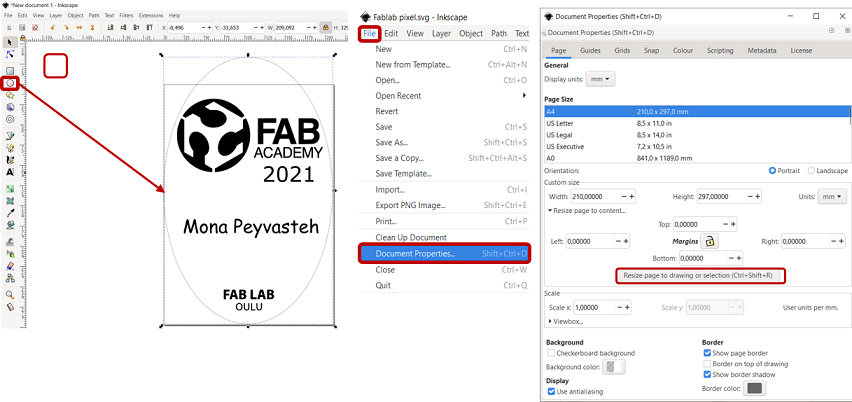
Figure 10. Making frame around drawing
Now, the file is ready!
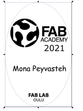
Figure 11. Final deign in Inkspace
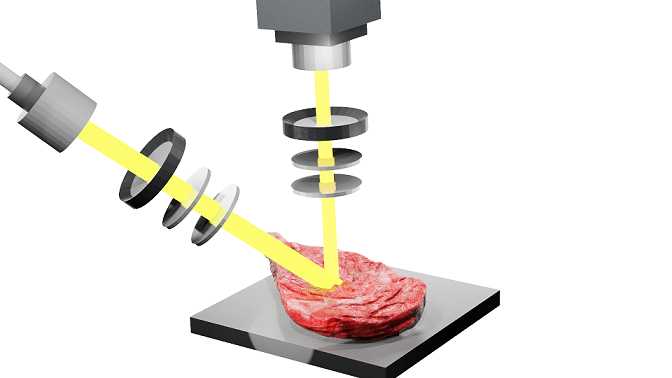
Figure 12. 3D Modelling Mueller imaging polarimetry measuring a meat sample with Blender.
To learn a new software and also, after discussing and exploring the pages of the former Fab Academy students, I decided to work with Autodesk Fusion 360 for 3D modelling part of the program. As the first step, I just watched some tutorials in YouTube ( example 1 and example 2 ) to get familiar with Fusion environment and learn some basic features.
Shortcuts in Fusion 360:
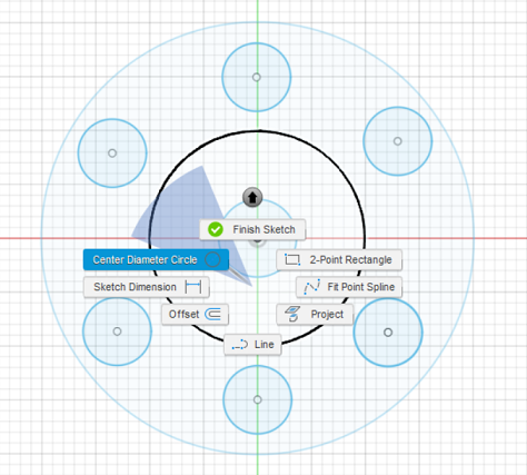
Figure 13. Drawing sketches with Fusion 360.
By clicking S (Model Toolbox), search for Center Rectangle and click the arrow to add it to Toolbox. To extrude the circles, Selecting Create >> Extrude or simply press E, click the surface and then dragging it up and setting the height you desired (Figure 14).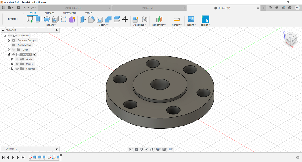
Figure 14. Extruding with Fusion 360.
Then, I added new components including the six legs and the lower plane. After that, I joined the components through Assemble button and finished the primary modelling of hexapod platform.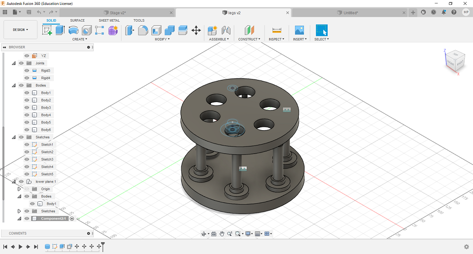
Figure 15. Basic Hexapod drawing with Fusion 360.
During this week, I learned about raster and vector concept in addition to learn some new features in GIMP. Then, I started to work with Fusion 360 for the first time that was a bit challenging in the beginnig but then, turned interesting. I also learned some new features using Inkspace.