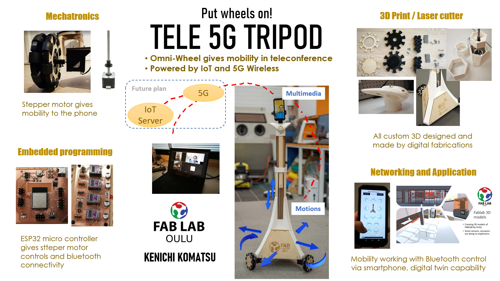
Final Project - Tele 5G Tripod
1. Purpose
The goal of Final project is creating a machine using 5G/6G research and the project demo. My research topic is Time Sensitive Networking on beyond 5G mobile communications.
The requirements of 6G machine is,
- Multimedia streaming Quality of Service
- Low latency real time communication
- Real time synchronization between things and wireless communication netowork backend
Here, the technology of 6G connectivity is not yet come (will be come at 2030!) however create the basic model of remote control machine with multimedia broadband with mobility.
1. Vision, who can be the user?
Now in 2021 is still being in pandemic,,, people needs to work remotely with video conference not only for international calls but also for local works due to many lock downs by COVID-19 restrictions globally.
This project helps people becomes more active in teleconference and more telepresence, more productivity in facilities in physical production fields.
2. Question to solve
What are the current problems on remote work under pandemic condition?
- Teleconfence is only fixed position video streaming, no control for video view directions and mobility.
- The video camera is in fixed position, inside of laptop, using a USB webcam or mobile phone.
- The remote side people cannot look around the place with fixed camera. Especially in Fablab work, remote people wants to look at their interested point in fabrication process. For example, 3D printer, CNC, which remote people can give more advices with the production status of settings and operations.
- Even if someone holds the camera of mobile phone, the view angle is not always what the remote people wants to see. Moreover, physically it needs someone standing on the site and phone holding arms be tired…
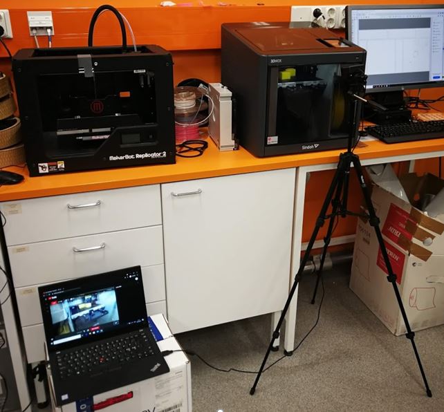
Many cases can be seen in Fablab, put tripod with camera with laptop video streaming and remote side can watch what happening on 3D printing…
2. Research & requirements
1. Idea/Concept
How about put wheels into tripod....?
If the tripod can walk around in Fablab room?
The machine idea
- Remote side user can see the video view where you want to see with your own smartphone control with interactive.
- Onsite side is as a smart phone holder, any video call capable phone can be set.
- The movement of holder is synchronized with remote side user ‘s smartphone of x,y,z axis positioning as moving tripod.
It can be put on the robot with mobility…
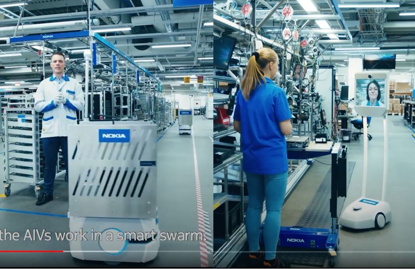
(c) Nokia, YouTube: Welcome to Nokia Oulu factory
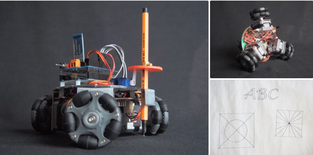
And past Fab Academy, there was a project of Omni wheel robot controlled by mobile phone via Bluetooth. (c)Fablab Kannai, Kota Tomaru

And other project of Omni wheel robot using NEMA17 stepper motor, Omni Wheel CNC Plotter.
Fablab Oulu 3D models are already created. VR tool can control the 3D objects can simulate the movement virtually.
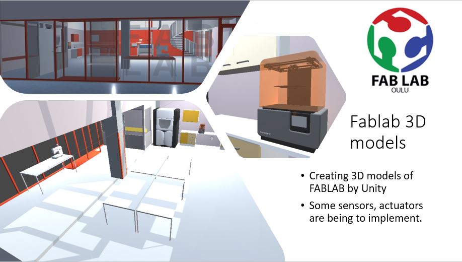
In practice the remote control is difficult by only using a camera whose view from the phone only. 3D virtual reality can support the other visions with preferable view, also supports the automated movement into the destination, viewpoint.
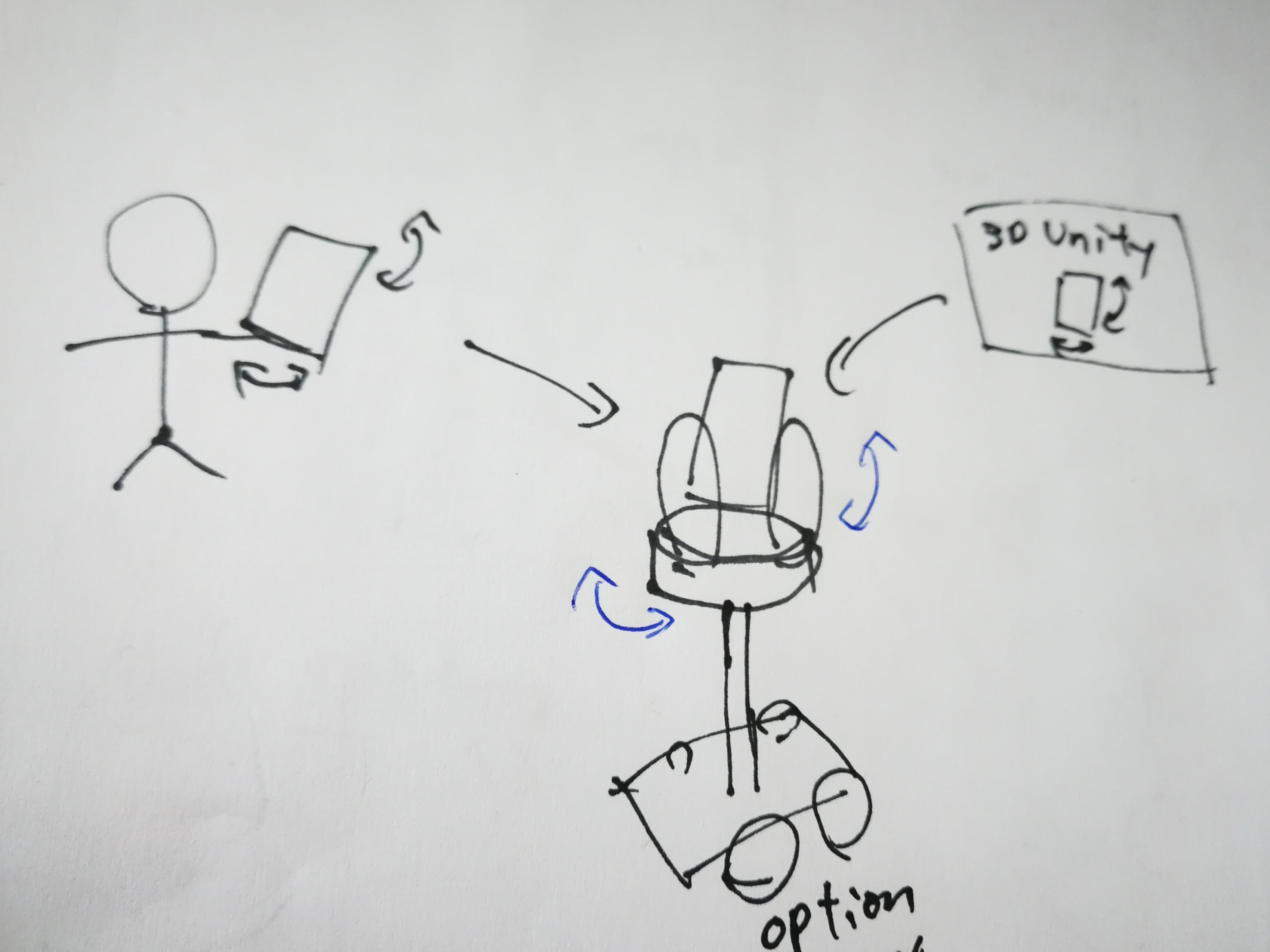
The image of how to sync with phone and 3D unity movement.
2. Licensing and scope
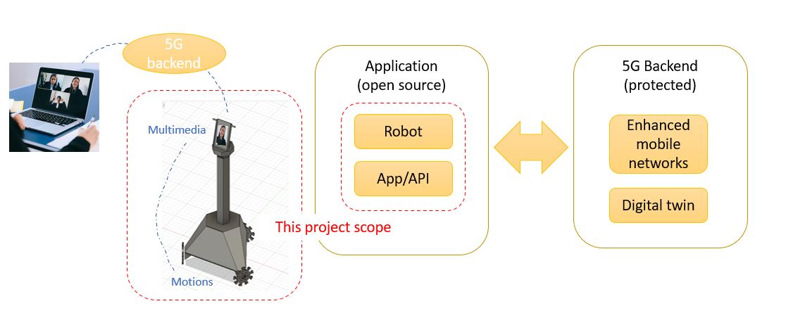
My project is a demo of my PhD. research in University to verify the performance of mobile network and its proof of concept. Here, I clearly define that this Fab Academy project scopes only the robot mechanics and mobility control application and API as open source. However, how to control remotely with the backend of enhanced mobile network technology with digital twin is to be protected property with my PhD. study with its stakeholders.
I take Creative Commons for physical fabrications (robot designs, electronics PCB designs), presentations and videos. And for software codes of embedded programs, mobile Apps, I take MIT license for the source code distributions.
3. Fabrication requirements
Here is the feature requirements of Tele 5G tripod,
- Teleconference interface (Camera, LCD, microphone, speaker)
-> by commercial smart phone.
- Physical interface for holding the phone is given by the 1/4 inch screw as normal commercial tripod. The phone can be hold by commercial tripod holder.
- Elevation of the phone
-> Stepper motor with thread rod that rotation gives elevation.
- Mobility X/Y physical movement with wheels
-> Three Omni wheels 3WD powered by NEMA17 stepper motors.
- Bluetooth connectivity with smartphone.
The mobility of Tele 5G tripod is provided by omni wheel which provides X/Y movement without steering, the moving direction is given by the difference of wheels.
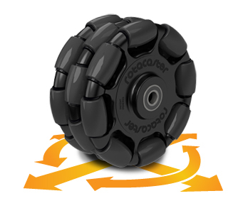
(c)Rotacaster Wheel Pty Ltd
4. Bill of materials (BOM)
The cost calculation from components are,
- Tripod head & body: 325€
- Omni wheels: 122€
- Electronics: 118,05€
All total 565,05€.
A complete BOM list of materials and components can be found from Final Project Cost Calculations.
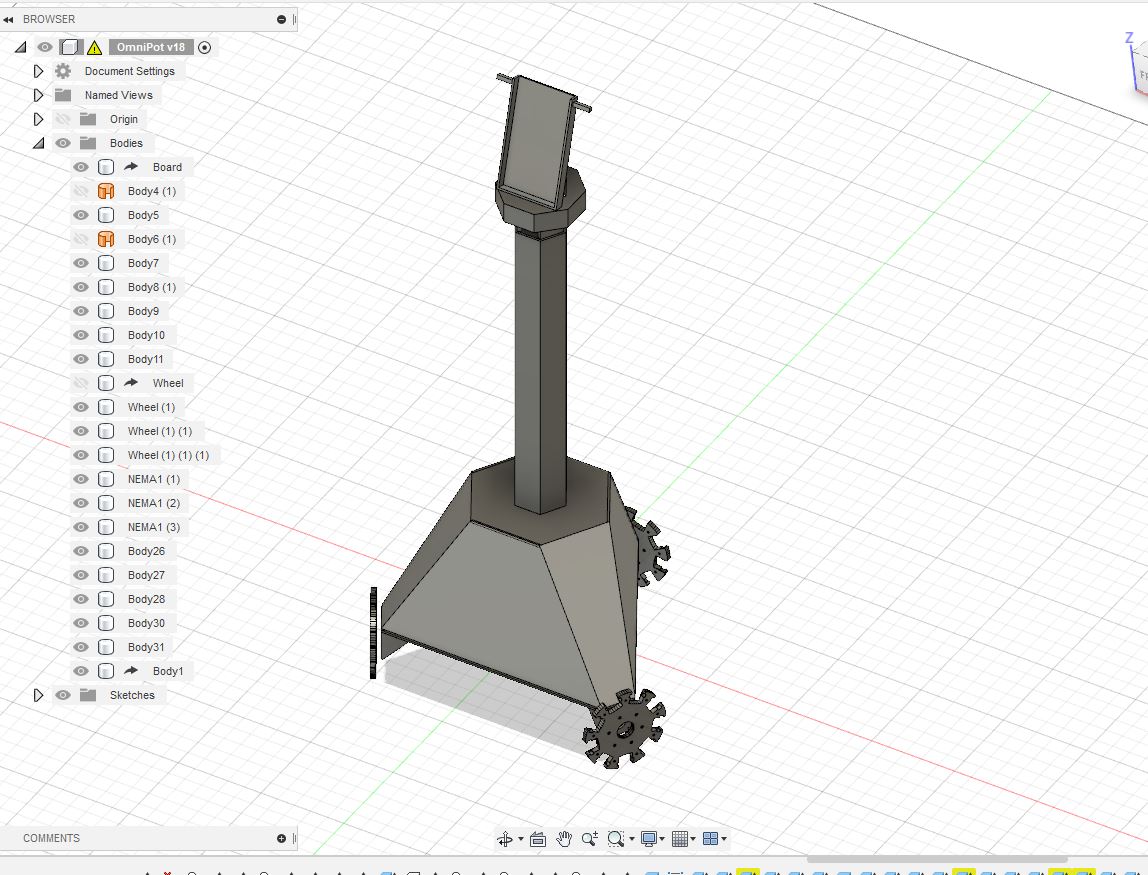
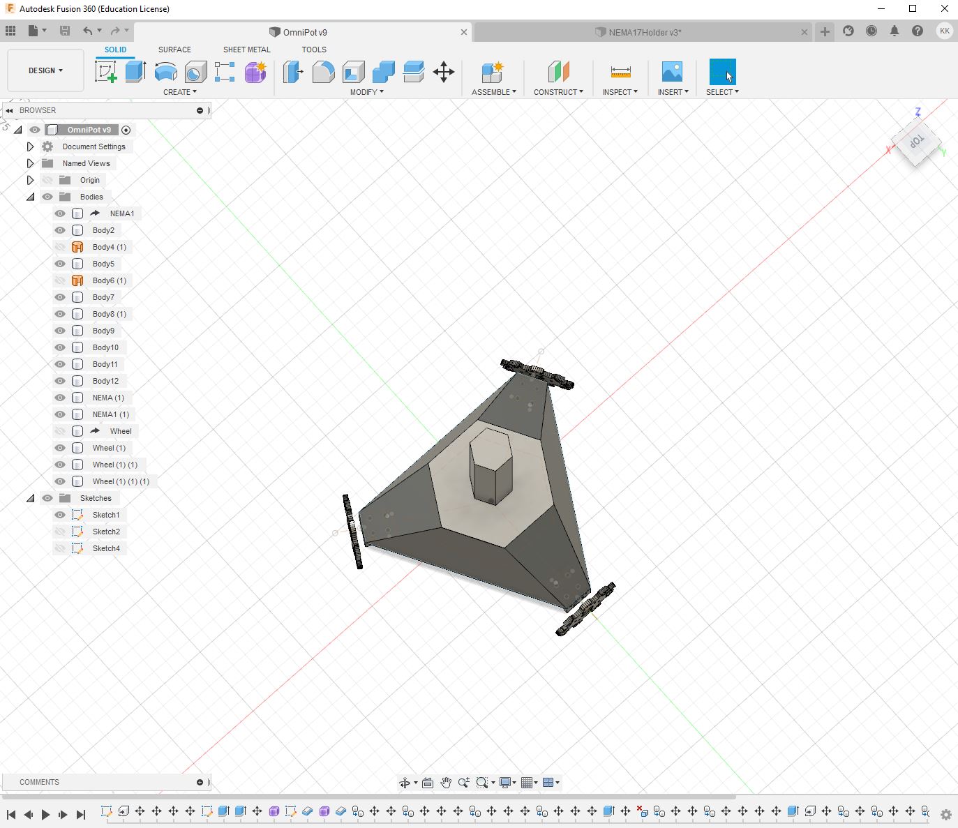
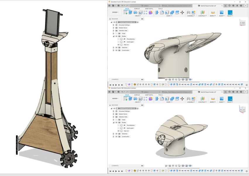
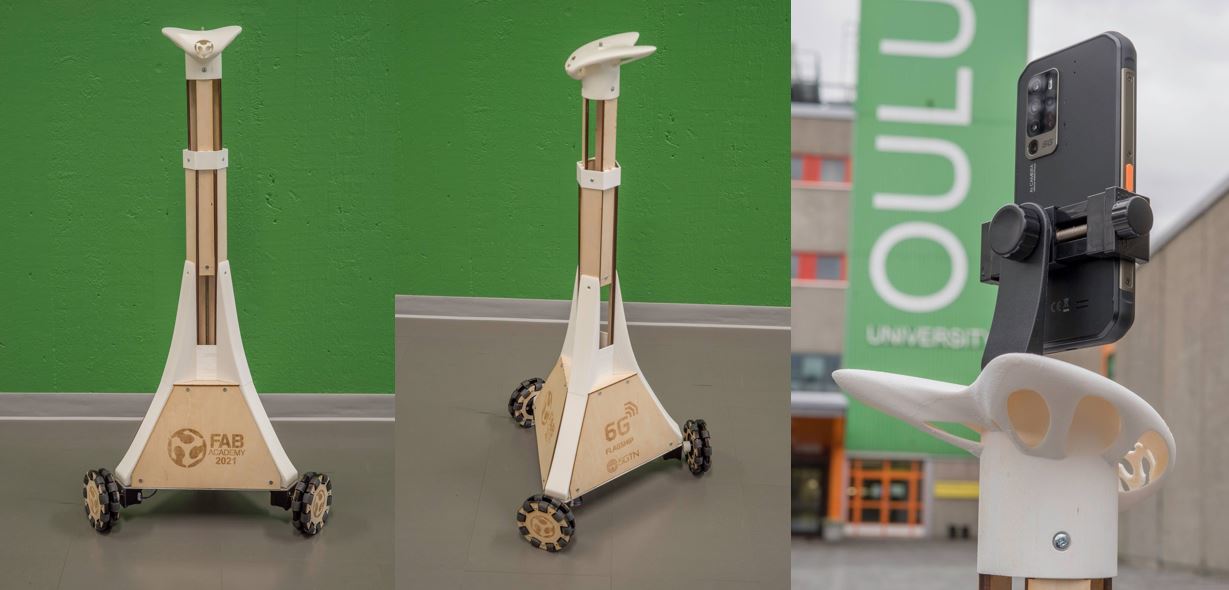
2. Mechanical design and fabrication
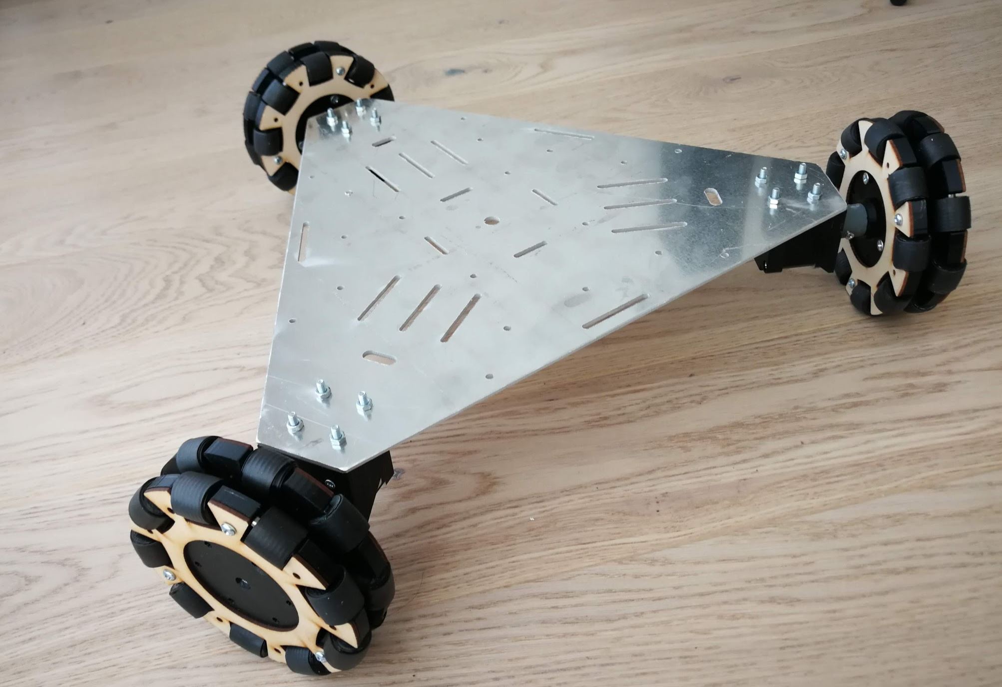
This is the mechanic’s sketch. The big picture of this product is “Tri”pod, put the basic structure concept as triangles, hexagons, 3x6 baseline.
- Three Omni wheels drive mobility of the machine.
- Omni wheel 3WD provides the movement of X/Y without steering.
- Tripod head height is roughly 70cm, can be extend to up to 110cm.
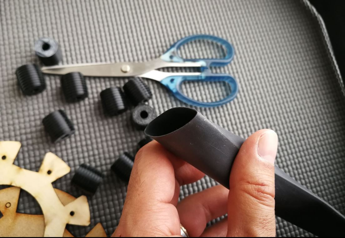
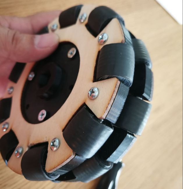
1. Omni wheel design (3D print)
I decided to make the omni wheel by DIY by 3D printer because,
- The project needs bigger wheels (more than 100mm) supporting the 1m height, roughtly 3-5kg object.
- Bigger omni wheel is expensive and less availability.
- DIY can make more modification depending on the use cases.
Omni wheel fabrication is started from the reference model in thingiverse but some challenges from the grip, rubber coat and 3D modifications. The details are reported here.
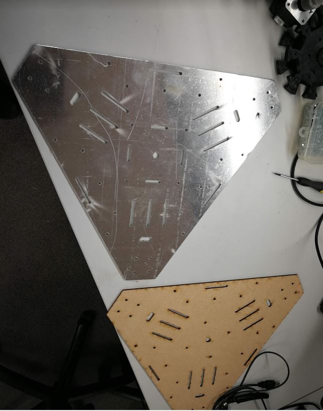
2. Rigid metal baseboard (Water jet cutting)
As mobility machine, also big scale of size such 1m height and 3-5kg, rigid structure is required. For the baseboard material, this time used 3mm thickness aluminum plane board cut by water jet cutter. This was made by wild card week.
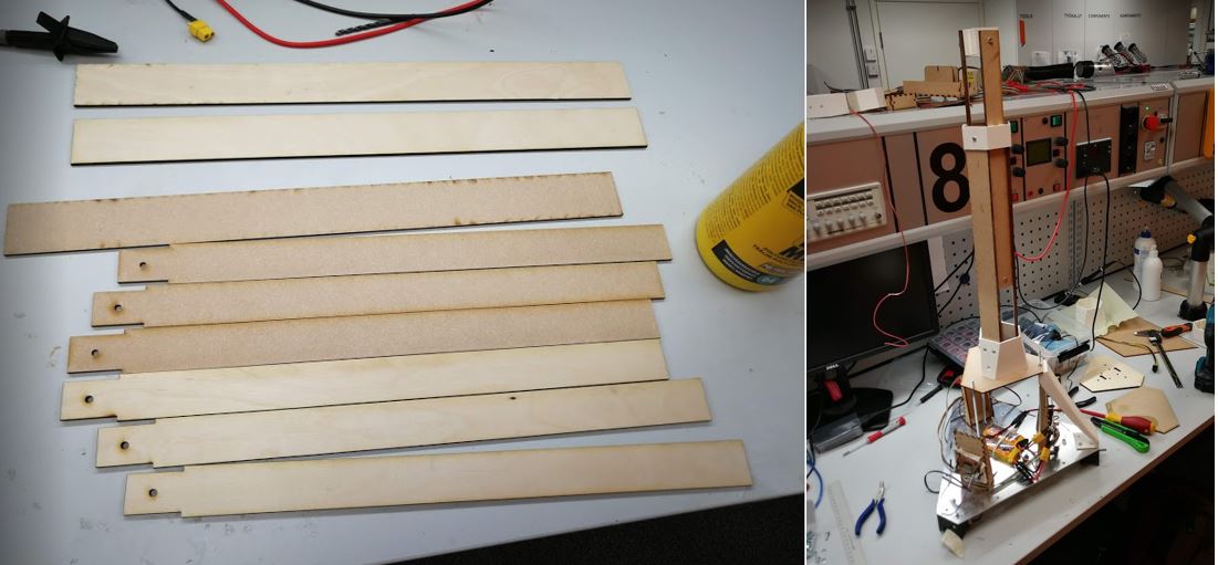
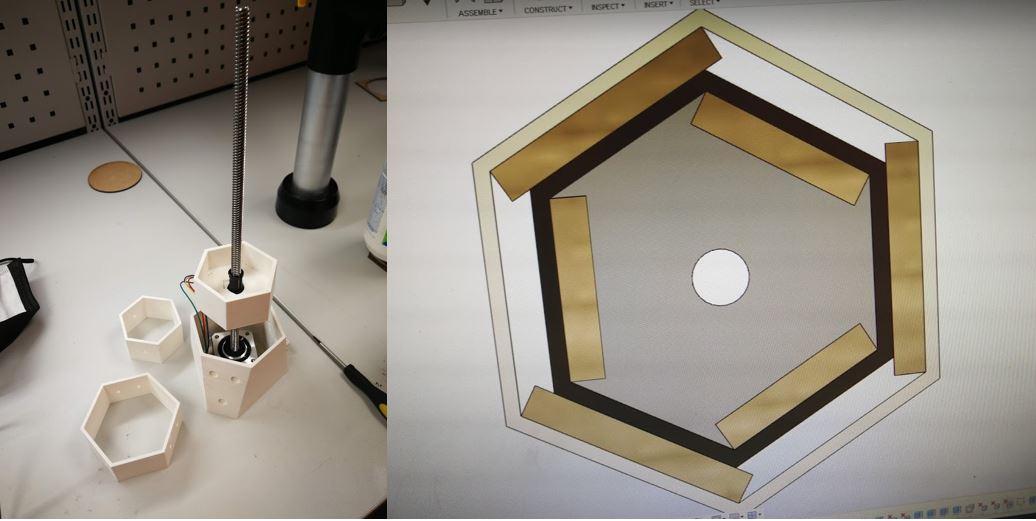
3. Tripod elevation tower (3D print and laser cutter)
The tripod tower is made the pilar consisted with plywood bars, three bars at the bottom part, three bars at upper part then makes hexagon shape from the top view. The bar is used 2 pieces 3mm plywood attached by glue made total 6mm thickness for the rigidness. The NEMA17 stepper motor and all pilar components are connected by 3D print holders.
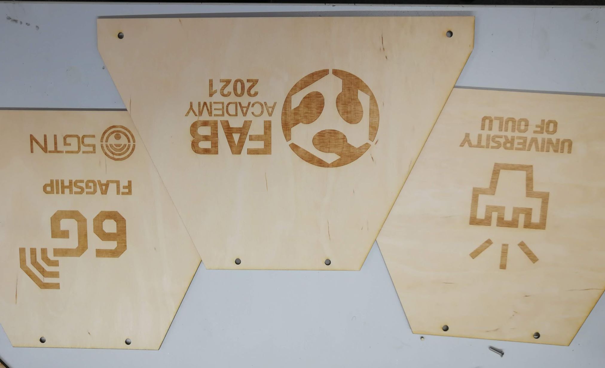
4. Body mechanics and cosmetics (3D print and laser cutter)
This activity was stretch from the original plan of minimum functional requirements, but I answered from Neil’s expectation “Please DO NOT make just a proto, such only MDF pressfitting… should be looking more product”. (Then my original plan was just pressfit everything by MDF…)
Fabricated by 3D print and laser cutting for plywood, The design detail is reported here.
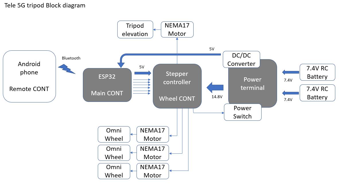
3. Electronics design and fabrication
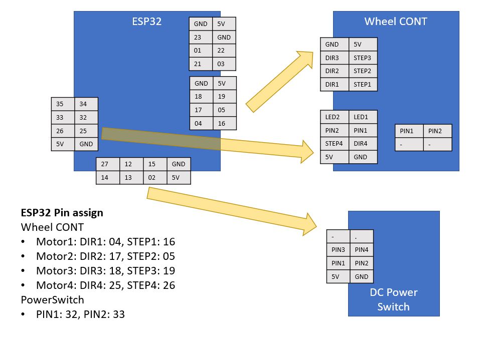
Embedded electronics part, the system is consisted with three functional blocks, ESP32 Main controller, Stepper drivers implemented Wheel Controller and the power terminal which connects battery and supply 5V from DC/DC converter.
And create three separate PCBs as modular concept. When one function needs to be updated and re-design, just replace the relevant PCB.
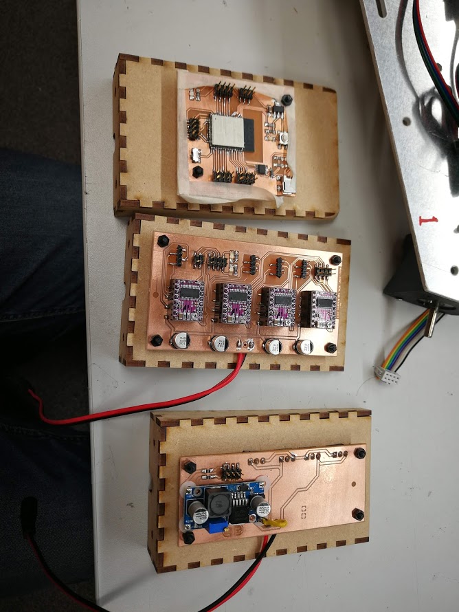
1. Embedded electronics design
Designed and fabricated three functional PCBs.
- ESP32 board is used the same one from Input devices week production.
- Stepper driver Wheel control board is referenced from Machine and automation week’s Pizza mayonnaise dispenser machine and also Output devices week.
- Power terminal board is very simple which has many screw terminal connectors to connect batteries as the power source (need 14.8V by series connection of 7.4V RC battery, also capable to connect another two batteries in parallel). DC/DC converter is from Fablab warehouse, to get 5V from 12V, DC/DC converter is much efficient than regulator. Regulator is basically resistance and exchanging as a heat to convert the voltage. This machine is battery operation so, the power efficient DC/DC converter is applied.
(Left: ESP32 board, middle: Stepper driver board, right: Power terminal board)
The cable connections from ESP32 to stepper driver board, power terminal board is here. All cablings are used 8pin (2x4) pin header connector with ribbon cable.
4. Application programming
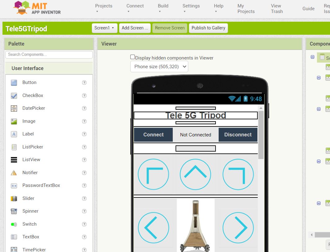
1. Networking & Application (MIT APP Inventor, Arduino)
The Bluetooth data sending/recieving function is followed the same way of previous week’s Strawberry application, and LED on/off via Bluetooth on App button.
The modifications for this Wheels control application are,
Mobile APP side:
- When press the buttons of direction arrows, get a string data of number which mapped with directions (leftforward=1, forward=2, etc).
- The number of string is sent on Bluetooth.
ESP32 side:
- Monitoring Bluetooth signal, when signal came, get the data and put into the variable.
- From the number on the variable, judge the command of which direction to move.
- Set the values of speed for each three stepper motor.
- Run the three motors according to the speed each.
- Loop above, motion stop means all motor speed make zero.
The tripod head elevation part is also same program to set the speed of elevation motor up/down.
Also the video is linked here
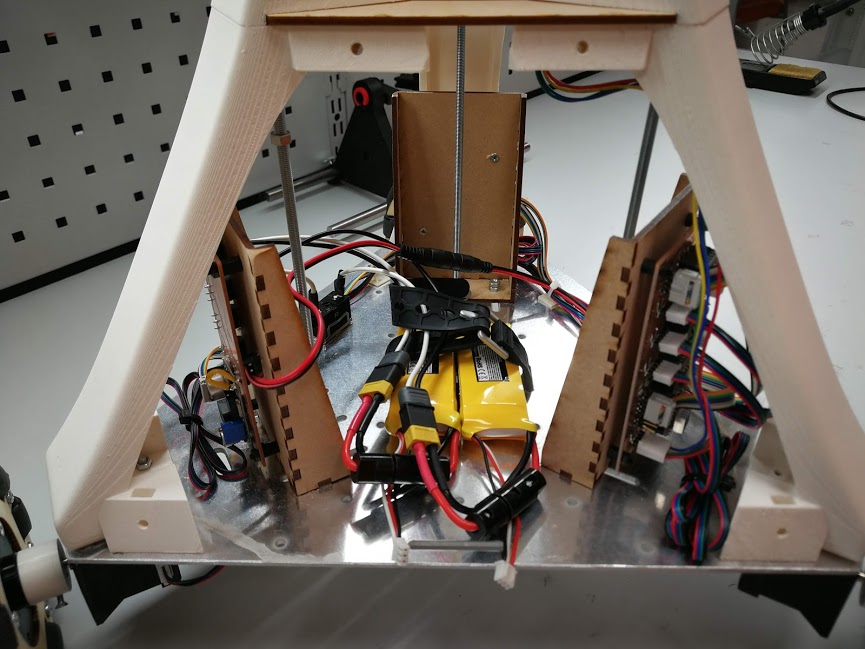
5. Final assembly, integrations
Mechanical integrations.
Electronics integrations.
The reason to locate the PCBs vertically, this can make more space for battery for future battery expansion (can change different system from LiPo).
6. Functional evaluation
Also the video is linked here
- Omni wheel machine can move X,Y direction and rotation accordingly from Smartphone control.
-> Omni wheels can move accordingly X,Y direction and rotation which controlled by smartphone APP buttons.
-> However, the speed is low due to less torque, or some stacked operation in Omni wheel movements. - Smartphone can be located on the tripod, and the height can be elevated by up/down by Bluetooth control.
-> Smartphone can be elevated up/down, you can see in the video which smartphone camera is elevated in front of the laser cutter. - The machine and smartphone can be controlled from remote site.
-> It cannot be control from remote site yet, but as jump start, using the Android APP of remote desktop such Team Viewer, then this would operate remotely Wheel control APP and teleconference APP from remote site.
-> Original plan was that Unity game engine controls the tripod via Unity’s Bluetooth API, but still need to research more. As functionality check of Bluetooth and ESP32 functionality, MIT APP Inventor is used for this project’s verification.
7. Lesson & learned, implications
1. Lesson & learned
Honestly speaking, I was optimistic to join this Fab Academy because I had experiences joining Hackathon weekend events of Fablab every year and most of the machines I knew how to use. However, fabrication reality as my own project was totally different story from the weekend event. First, own responsibility. Not only understanding of knowledge of the fabrication tool, try to use, do some success/mistake and learn how to recover the mistake next. What a practical manufacturing exercise it was! And responsibility for time management including documentations and presentations by my own working resource alone, this was not happened in weekend event (team work) and hobby type of activity(no deadline).
This Academy period went through by final project, the fruitful learning was 3D design and printing which I hadn’t experienced before. But also it was headache that 3D dimensions hassling,,, many remake happened when I assembled the mechanical components especially made by 3D printer. Many cases are less margin on 3D printing. Need to think about the tolerance of design, materials and tools. Especially towards integration of components, keep eyes on carefully about the interface faces which integrated.
And technically, omni wheel 3WD operation brings much benefit for remote control because of no steering, just left/forward/backward/right direction. However, the precise movement is up to the frictions between wheels and floor. Many things need to be considered.
2. implications
Very slow omni wheel movement:
Currently basic omni wheel functions are working but movement is very slow. Here is the possible root causes,
1. Less torque from the motor.
2. DYI Omni wheel’s quality.
1.’s Stepper motor torque is varied from the current from the power, this machine is powered by LiPo battery. However, I tried wired stabilized DC power source with maximum current, but same behave… Further study option is to use the geared stepper motor which has more than double torque by the gears.
And DIY omni wheel side also need more study. Now less torque means that caused by big diameter of wheel as well. The quick check can be done by using commercial 60mm diameter omni wheel.
Remote connection:
Basically, all physical fabrications are done, basic functionality is ready as moving tripod such X/Y movement by omni wheels and Z direction by motor rotating elevation, also controlled by wireless Bluetooth connectivity. However, this machine is not yet fully remote control from outside via internet/5G. As I declared above licensing & scope, enhanced remote control part is my PhD. study and out of this time scope. Nevertheless I continue this study and how the mobile network controls the things as digital twin is going to be my PhD. thesis and definitely it needs proper use case of proof of concept. Stay tuned and I keep forward with 6G research with this my physical avatar!
Used files
- 3D print files (STL)
- Coding files (Arduino, APP Inventor)
- 3D design files (Fusion 360)
- Laser cutter files (Fusion 360)
Acknowledgments
First of all, thank you my supervisor Prof. Ari Pouttu for allowing me to join this Fab Academy besides 6G flagship researching tasks. And thank you Nokia line managers (Mikko Laamanen, Jarno Pulkka, Jami Järviö) for allowing me to work in University 6G flagship activity on top of R&D works, and Olli Liinamaa who bridged me nicely between academic University and industry Nokia for common research tasks.
Then great great thank you Jani Ylioja, who is director of Fablab Oulu, for entering me to this academy and always meaningful advices me about fabrication capability since we met at Science Hack Day of 2018. Also Antti Mäntyniemi and Iván Sánchez Milara who organizes people and facility for our daily tasks in Fablab Oulu. And technical solution especially in embedded electronics, big support by Juha Pekka Mäkelä, and without any all other Fablab Oulu instructors’ supports, this couldn’t make happened in Fab Academy 2021 at the Oulu end.
And finally, a huge thanks and big love to my wife and daughter. This Fab Academy was to me “Tough Academy” intensive everyday works every week lectures in 6 months since January on top of my normal working hours. However, thanks to that hard work, big results achieved now. Thank you again all!
![]()