3. Computer controlled cutting
Assignments
Group Assignment
characterize the features of the laser cutters including focus, power, speed, frequency and kerf for different materials
Individual Assignments
- Cut something on the vinylcutter
- Design, lasercut, and document a parametric construction kit, accounting for the lasercutter kerf which can be assembled in multiple ways. For extra credit, include elements that aren’t flat.
Behnaz Norouzi, Fab Academy 2018 alumni, gave us the local lecture about Computer controlled cutting.
1. Research
Here is my new learnings from Neil’s lecture.
Half tone tool for Laser engraving is shown here. Laser engraving is a kind of burning the material, there are several techniques to nice way and even bad way…
Many Joints structure, very simple one, complex one but better to try first for fitting the use case.
- pressfit
- chamfer
- snap-fit
- fixture
- pinned
- finger
- snap
- wedge
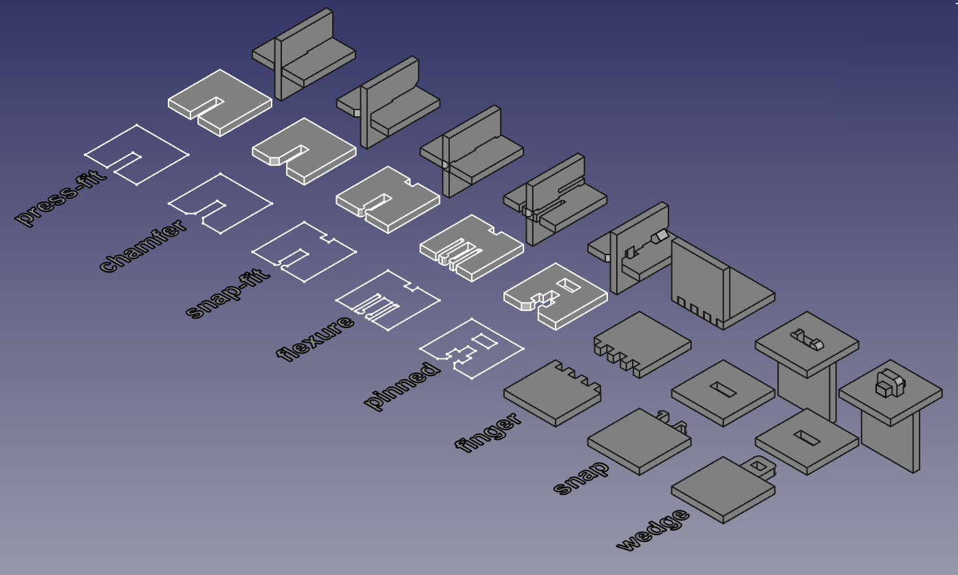 (c) Fab Academy class, Computer-Controlled Cutting
2. Group assignment
1. How to use the Laser Cutter Epilog Fusion M2 40
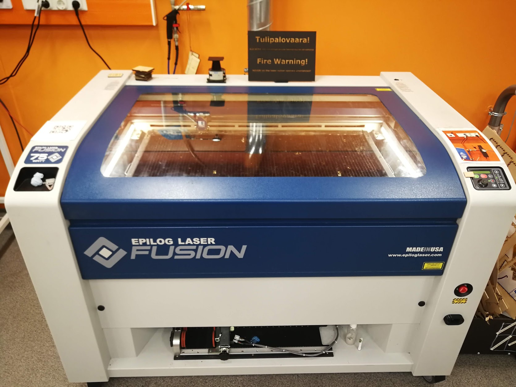
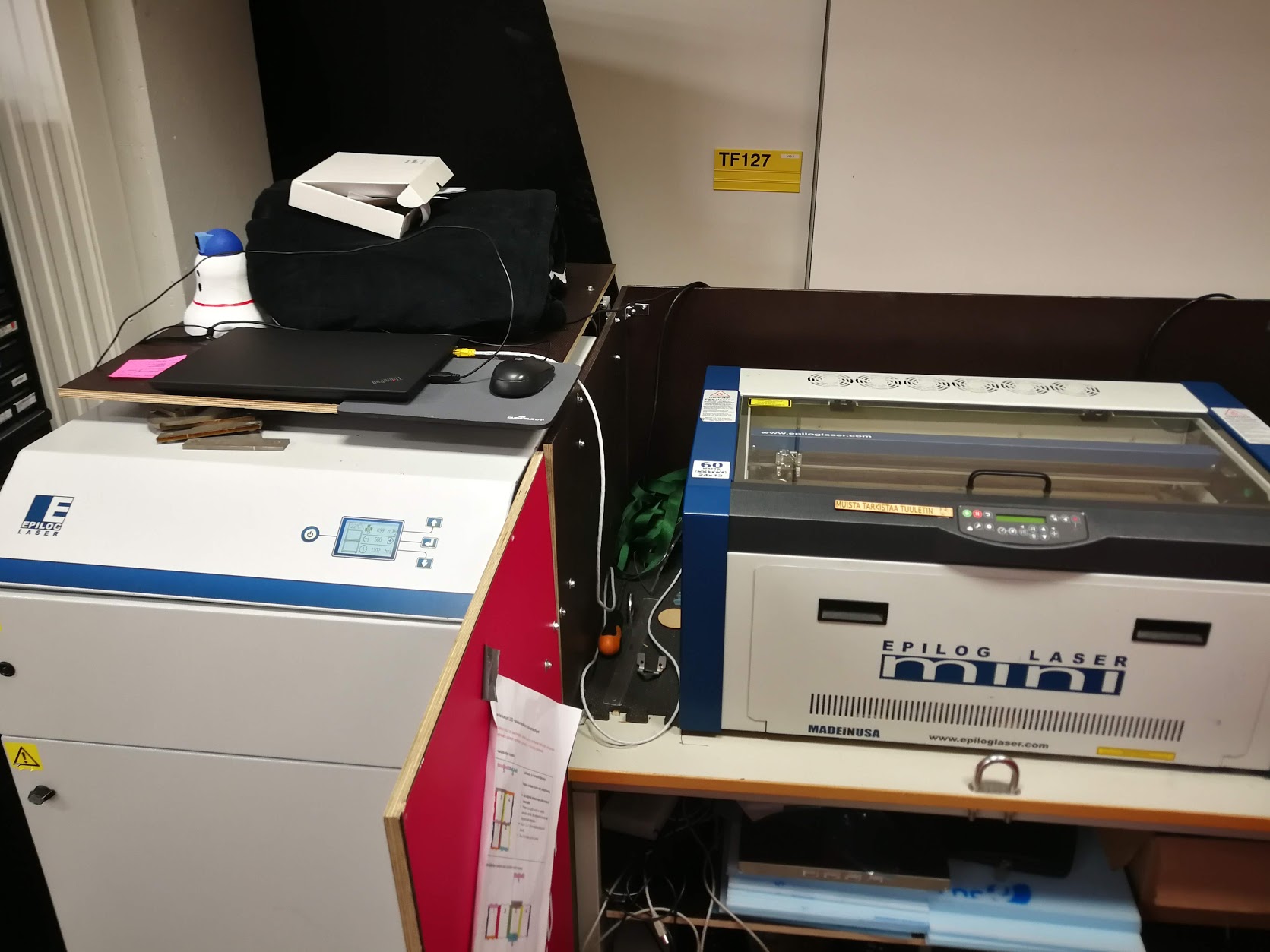
In Fablab Oulu, we used Epilog Fusion M2 40 Laser and Epilog Mini 24. “Laser cutter” is essentially the tool in order to cut by burning. It makes smoke and fire always, definitely take care the safety mind and correct procedures.
Safety instruction for laser cutter
- Do not run the laser unvented.
- Keep eyes on, do not leave from machine during the cutting (The beep alarm happens when you left from the machine).
- Put the air exhaust ON.
In case fire frame of the board, call instructor. Use the fire mat first and prepare to use the Fire extinguisher.
Setting and how to use
Laser cutter setting point is these three before print start,
1. JOG: To set the laser head position as its origin.
- Epilog Fusion M2: Set the position by joy stick and push the joy stick center.
- Epilog Mini 24: Set the position manually and set.
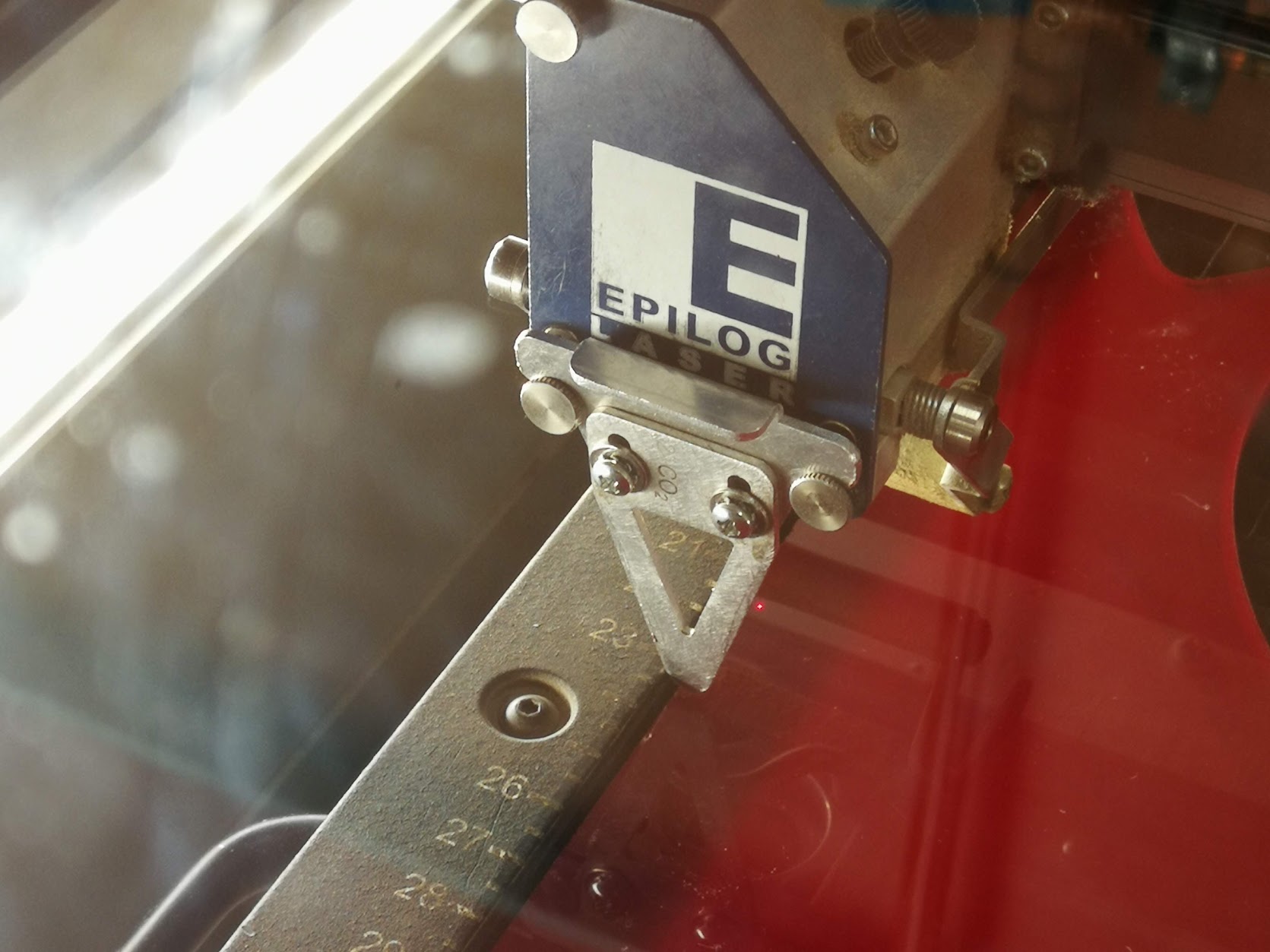
2. FOCUS: Laser needs the focus to burn the material efficiently, otherwise the material cannot be cut well. The focus distance is varied by the material thickness, when the material change, every time need to check the focus.
- Epilog Fusion M2: Need to set manually, choose focus and use the joy stick to move the head up/down. Use the triangle jig to make sure the distance from the material to laser head.
- Epilog Mini 24: Focus is automatically done, not need to set up.
3. JOB: The printing data is set from the PC next to the laser cutter. The file name is shown in the display, choose the file and push GO button. This procedure is same for both Epilog M2 and Mini.
Epilog Fusion M2 40 Laser
Epilog Mini 24
Laser focus jig.
2. How to set the kerf, other production related parameters
Laser cutter settings
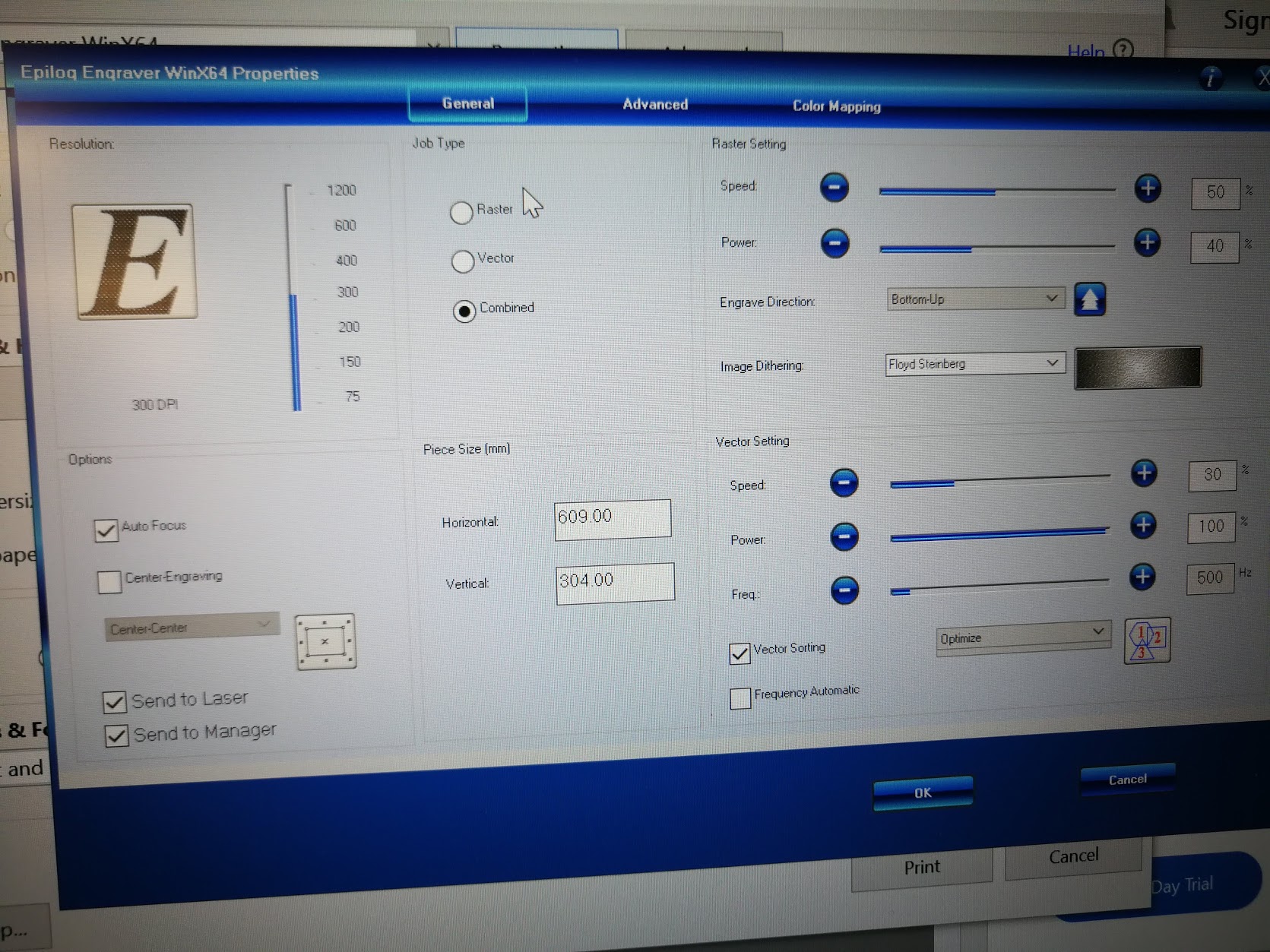
For setting the performance of laser cutter , there are three parameters,
1. Speed (S)
2. Power (P)
3. Resolution (DPI)
Here is the setting window which shows as the property of printer in PC. Usually, you should select the default settings from the menu, by depending on the material and its thickness. However, you can modify the parameters depending on the condition and your requirements.
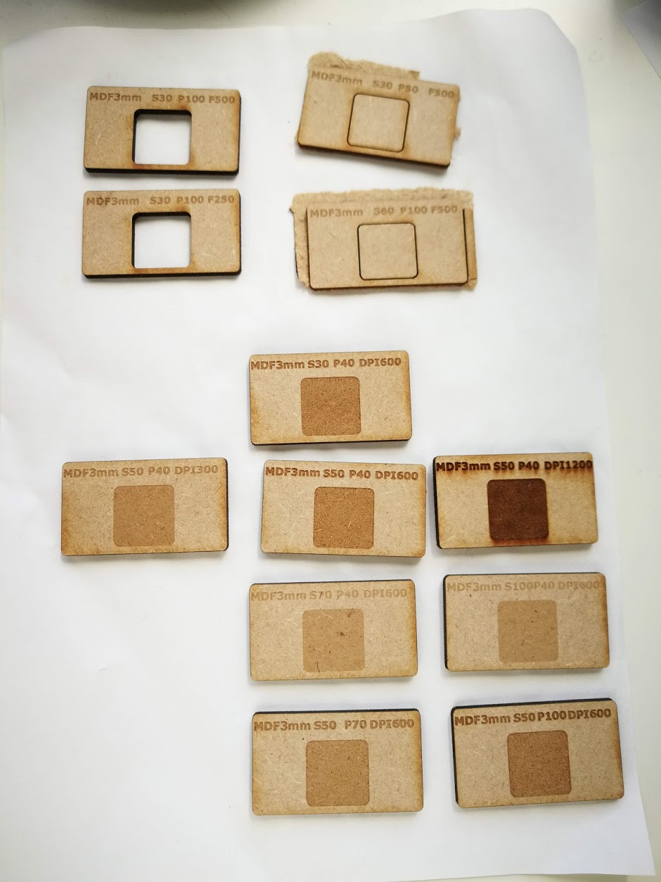
Cut tests
Here is the test result. The test result showed,
1. Cut: Less power and less speed cannot cut well.
2. Engrave:
- S: Slow speed makes strong engraving, faster speed makes shallow.
- P: More power makes stronger engraving.
- DPI: Higher resolution makes stronger engraving.
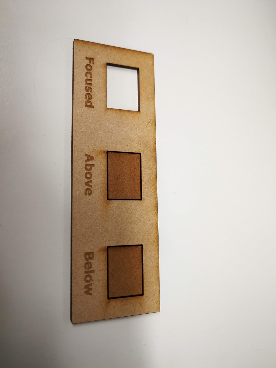
Here is the focus test result. The wrong focus on above/below makes lower laser power on the material and cannot cut.
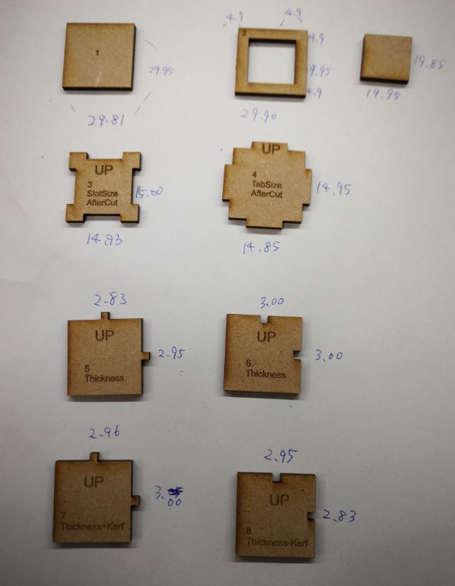
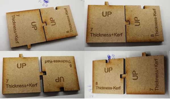
Here is the kerf test results.
Because of the width of laser beam, the outcome size can be varied by the laser beam kerf. Especially need to take care for press-fit joints, need test before the production. And laser width is different by X/Y axis, according to my test, it shows vertical line was made bigger kerf, and the press-fit joints margins were varied.
3. Individual assignment
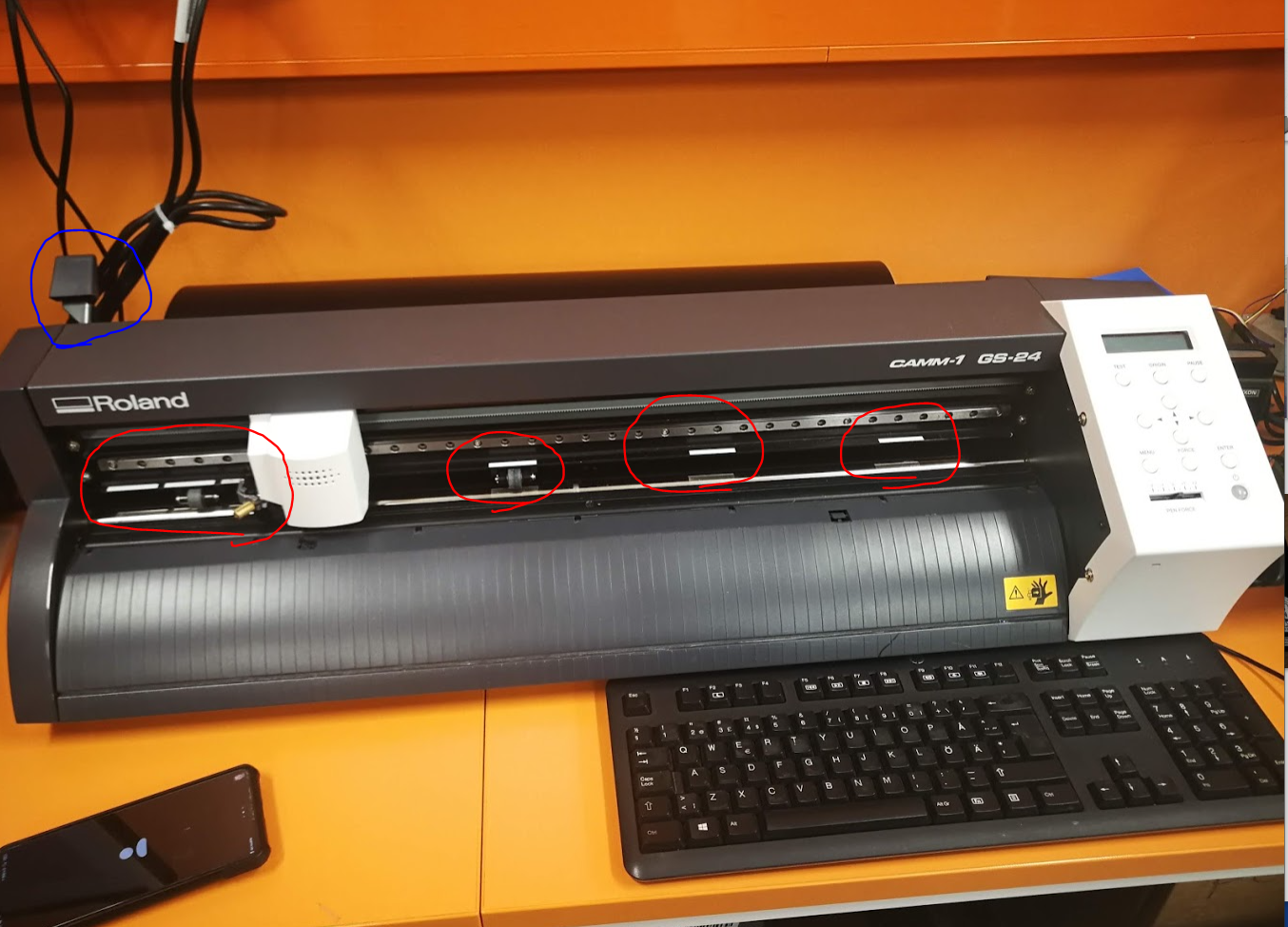
1. Vinyl cutter, Roland GS24
Keep close the lever (blue circle) when you are not using the machine. Put the pinch holders on the white line parts (red circles) depending on the material width.
- First put the material into Vinyl cutter from the backside.
- Check the cutter’s display and check Menu, “SELECT SHEET” has option of “Roll”, “PIECE” and “EDGE”.
- Choose “PIECE” shows W(Width) and L(length) of the material.
- Set the cutter head position by arrow keys and press Origin for one second or longer. Then the origin is set.
Open the .svg file by the Inkscape at the PC next to the cutter.
- Choose print.
- At the PC printer setting, press “Get” from the machine. Setting data is come from the cutter.
- Make sure “Rotate 90 degree”.
- Then Print.
If not cut well, check the blade of header or adjust “PEN FORCE”.
2. Vector design with Inkscape
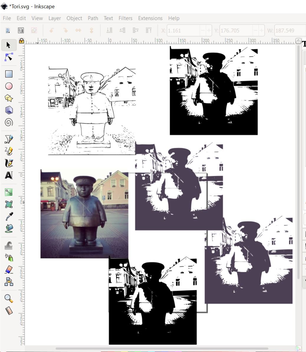
Toripollisi is a simbol of Oulu city where I’m living in. It is an bronze statue standing on the market place at the city center, because of the fatty cute outlook, everyone loves him and this is one of the sightseeing spot on this city.
I used Inkscape to make the vector data for vinyl cutter. First I tried to use “Trace Bitmap” to get black/white picture for cutting. I tried multiple settings though, the result was not satisfied level as sticker. The original photo was not simple.
Second try was outlining the edge of statue manually by using the Bezier pen tool. First rough sketch for the outline is okay.
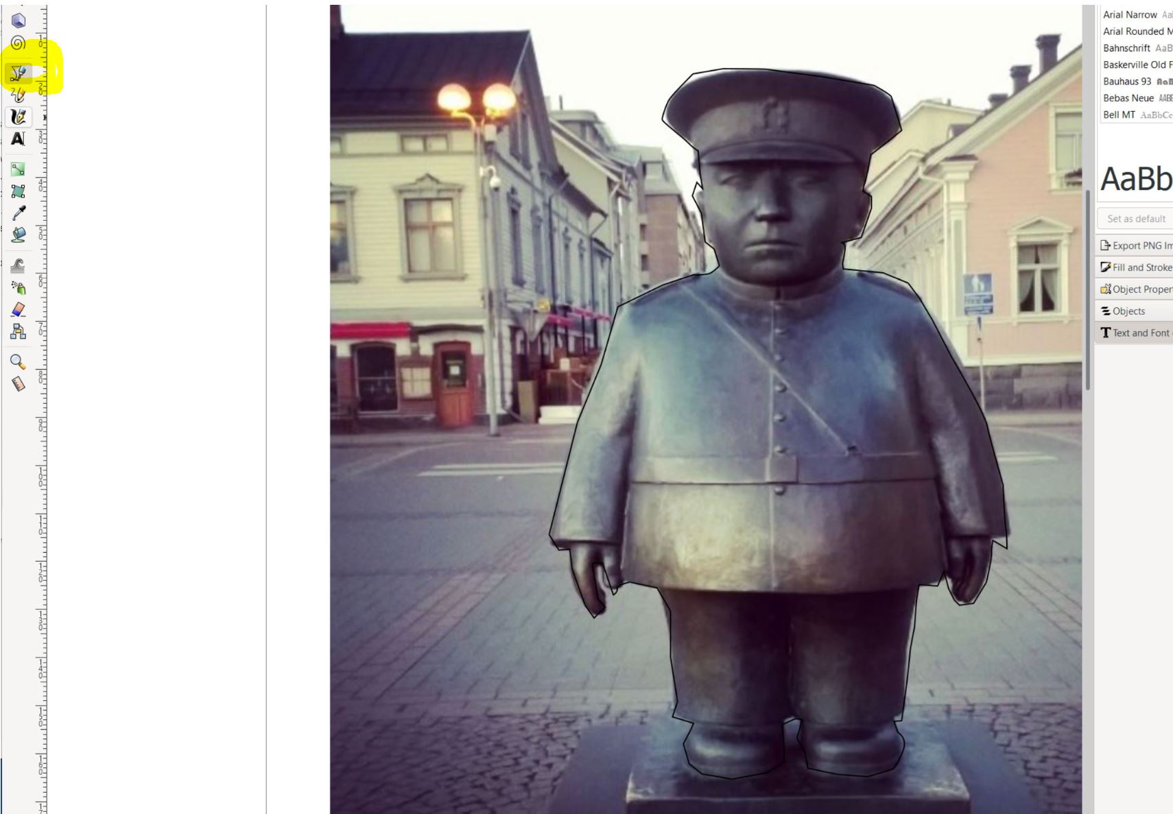
Then check the details with moving the dots. Upper line tools help the operation to make the curves with dots moving by several way.
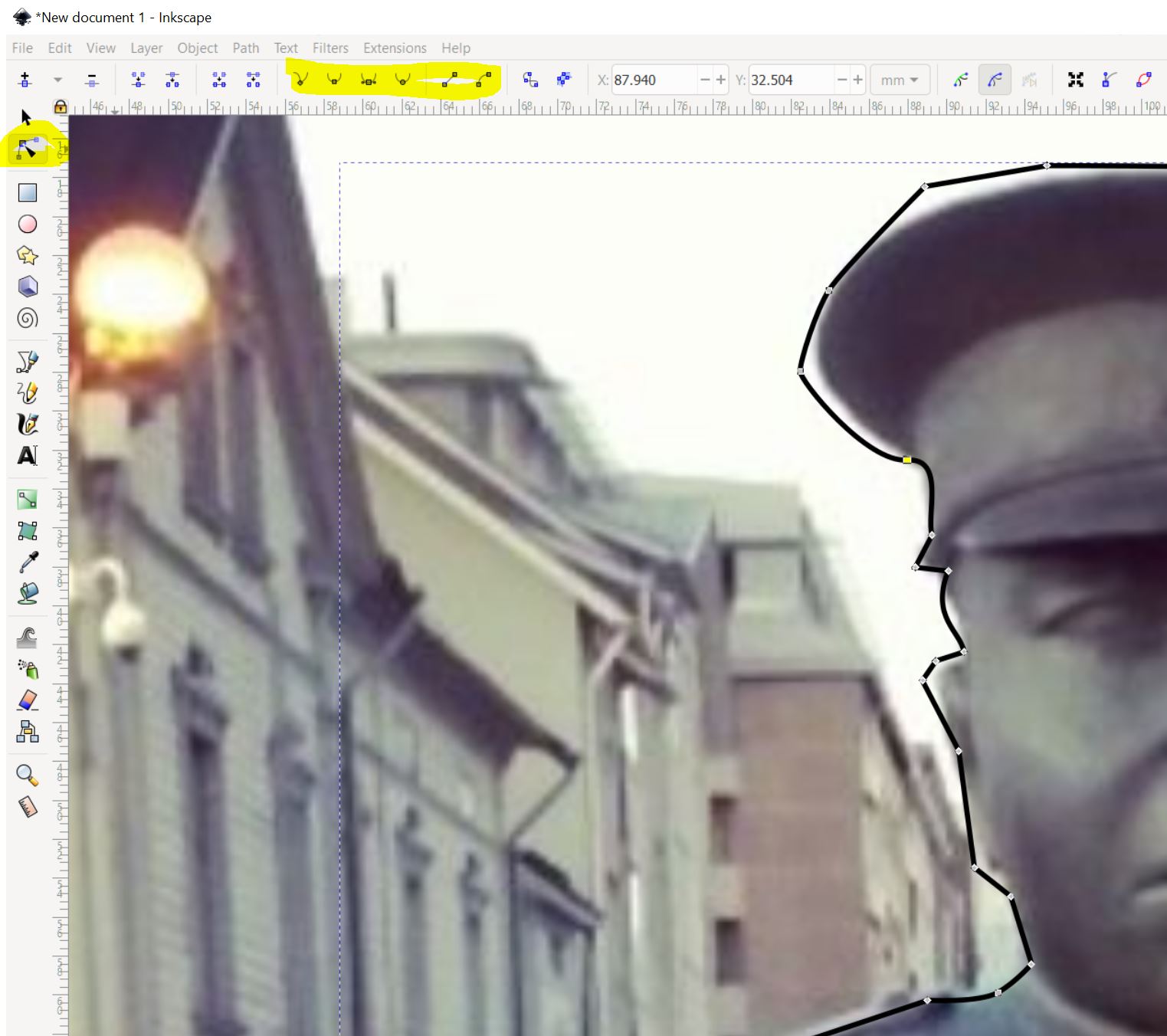
After finished the outline making, then clip the object of statue. Object -> Clip -> Set”“.
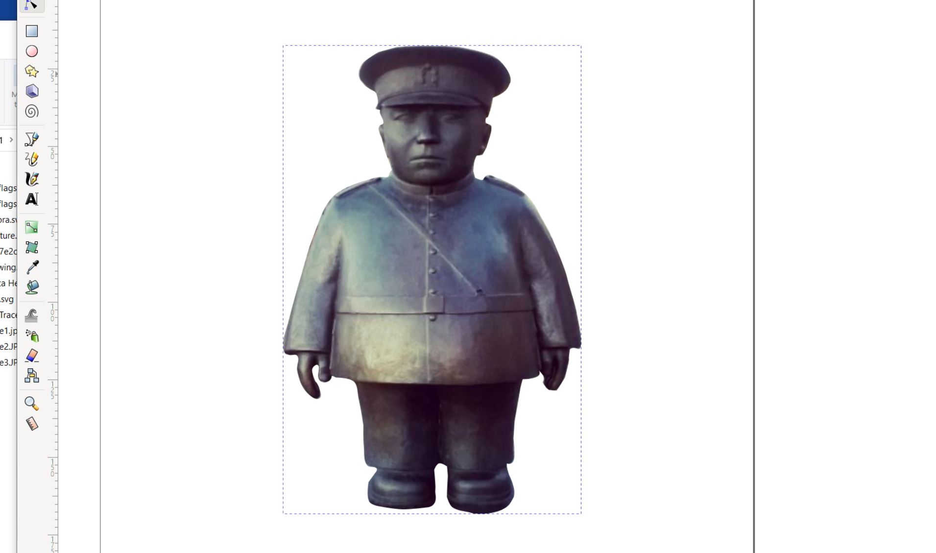
Finally added the texts.
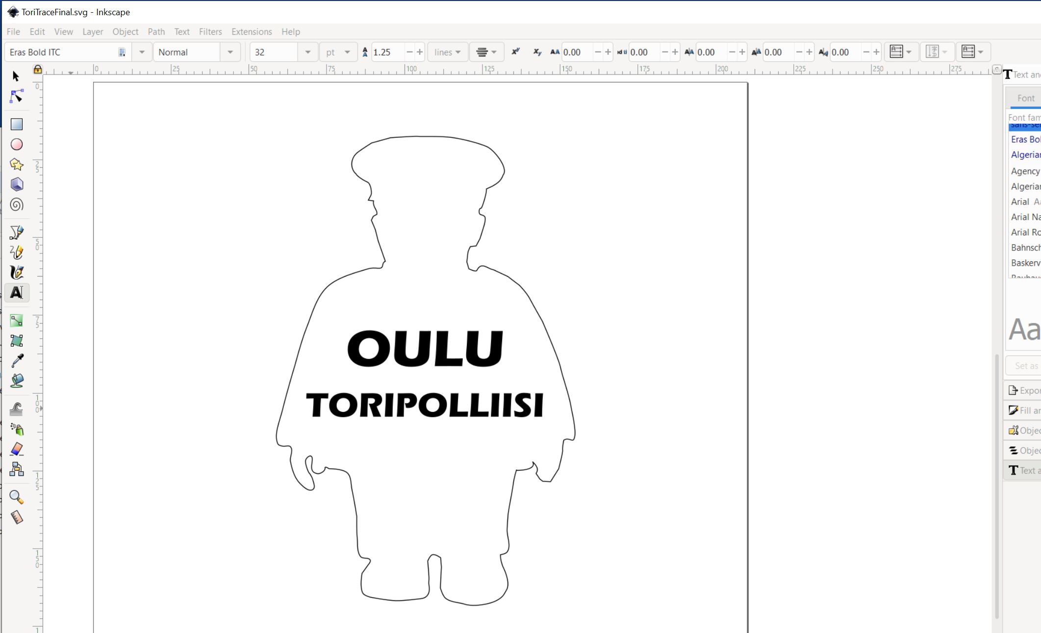
Finished the design, then save as .svg file.
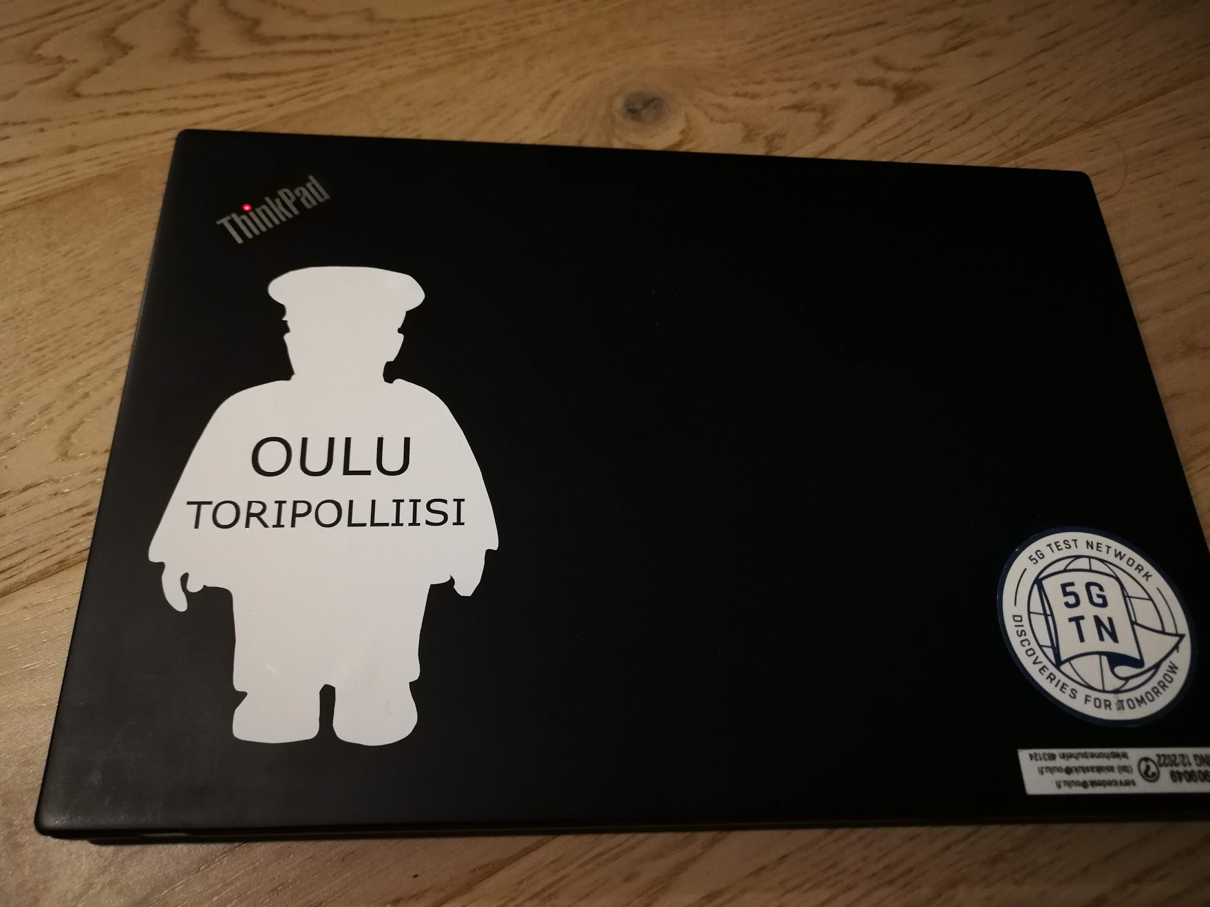
Cut the sticker sheet by vinyl cutter and pasted on my laptop!
Trick for letters
Cutting letters on sticker, difficult part is that letters can be disassembled, wrong positions where is not connected with the main part of sticker.
One solution is paste the masking tape all letter area, then pull out the sticker with masking tape together. Then paste it into object. The letter part unwanted objects are removed carefully by tweezers with removing the masking tape.
3. Parametric design creation
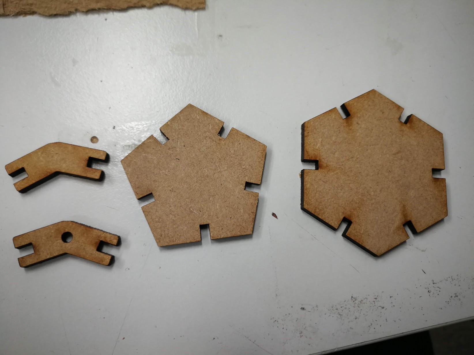
For parametric design, I decided to make Football shape of structure, because my kid likes football.
First I study the football geometry structure, it is called Truncated icosahedron, and the combination of pentagon and hexagon. It has 12 regular pentagonal faces, 20 regular hexagonal faces, 60 vertices and 90 edges.
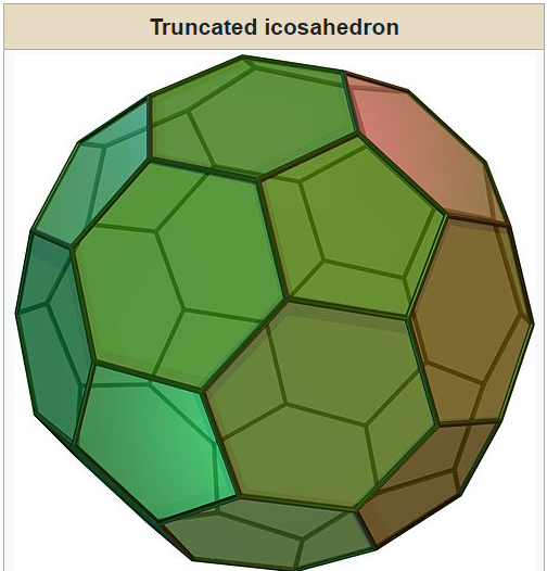
Picture: Wikipedia
For making by laser cutter and the board, the connection needs and the angle of connection is different from the combination of hexagon/pentagon.
Hexagon-Hexagon: 138.18°
Hexagon-Pentagon: 142.62°
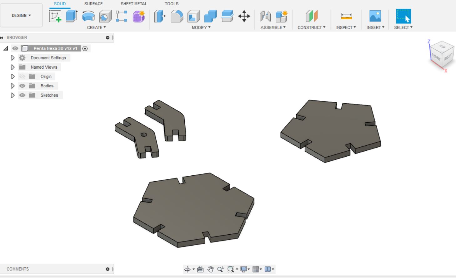
Desgin is made by Fusion 360 of Autodesk. At first, drew sketches by the tool Create -> Polygon then made the basic shape of pentagon and hexagon.
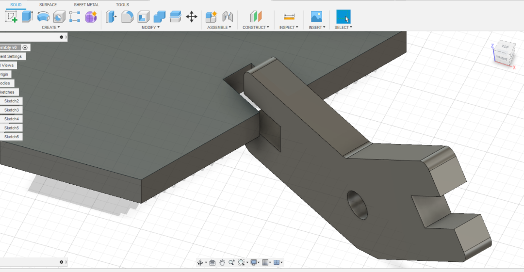
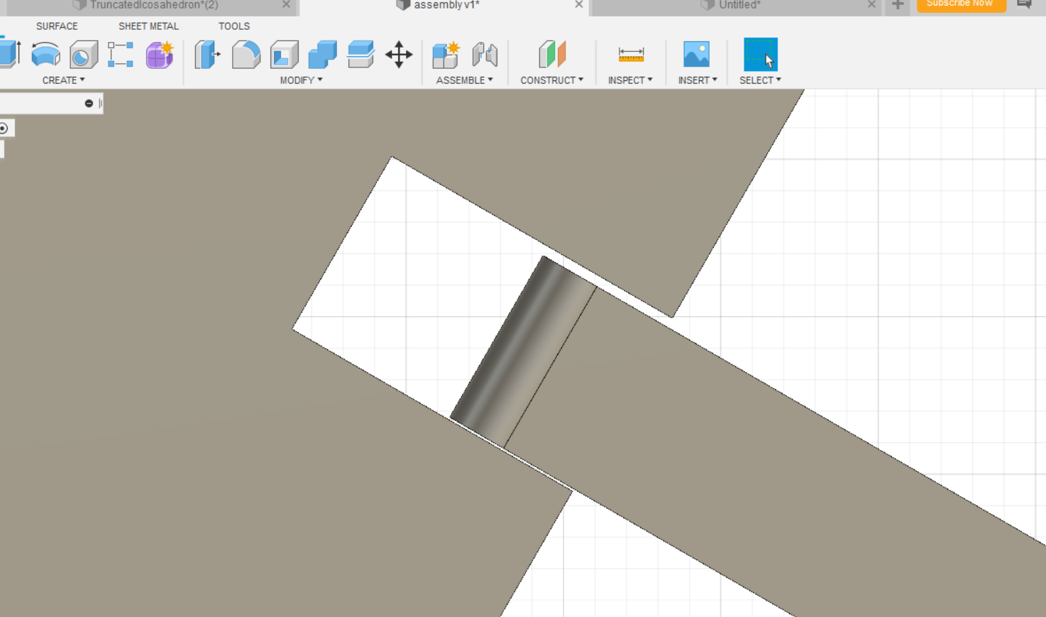
And in Fusion 360, I used parameters to set the size of shapes but also kerf for production. Kerf is used for the tub width of press-fit joints.
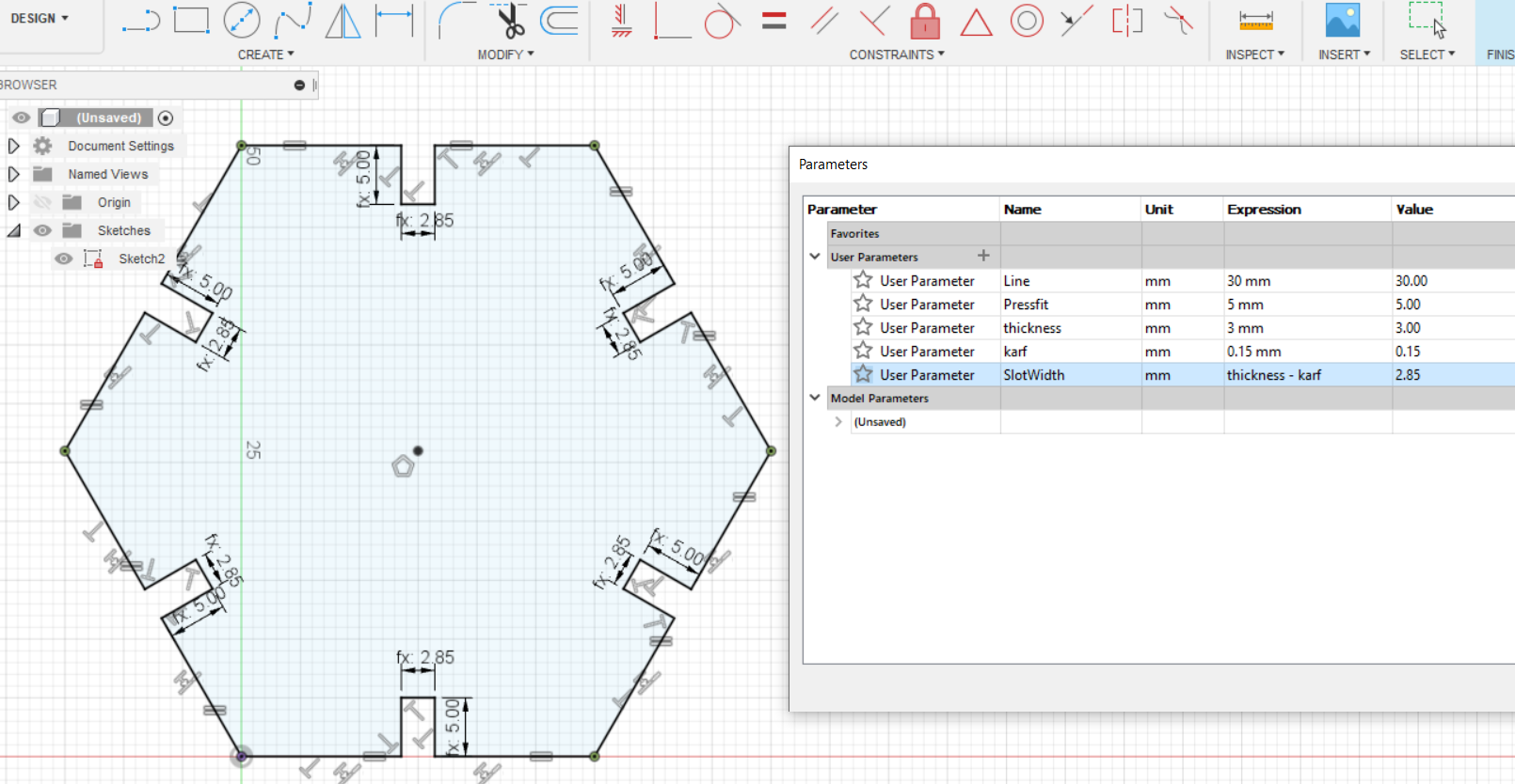
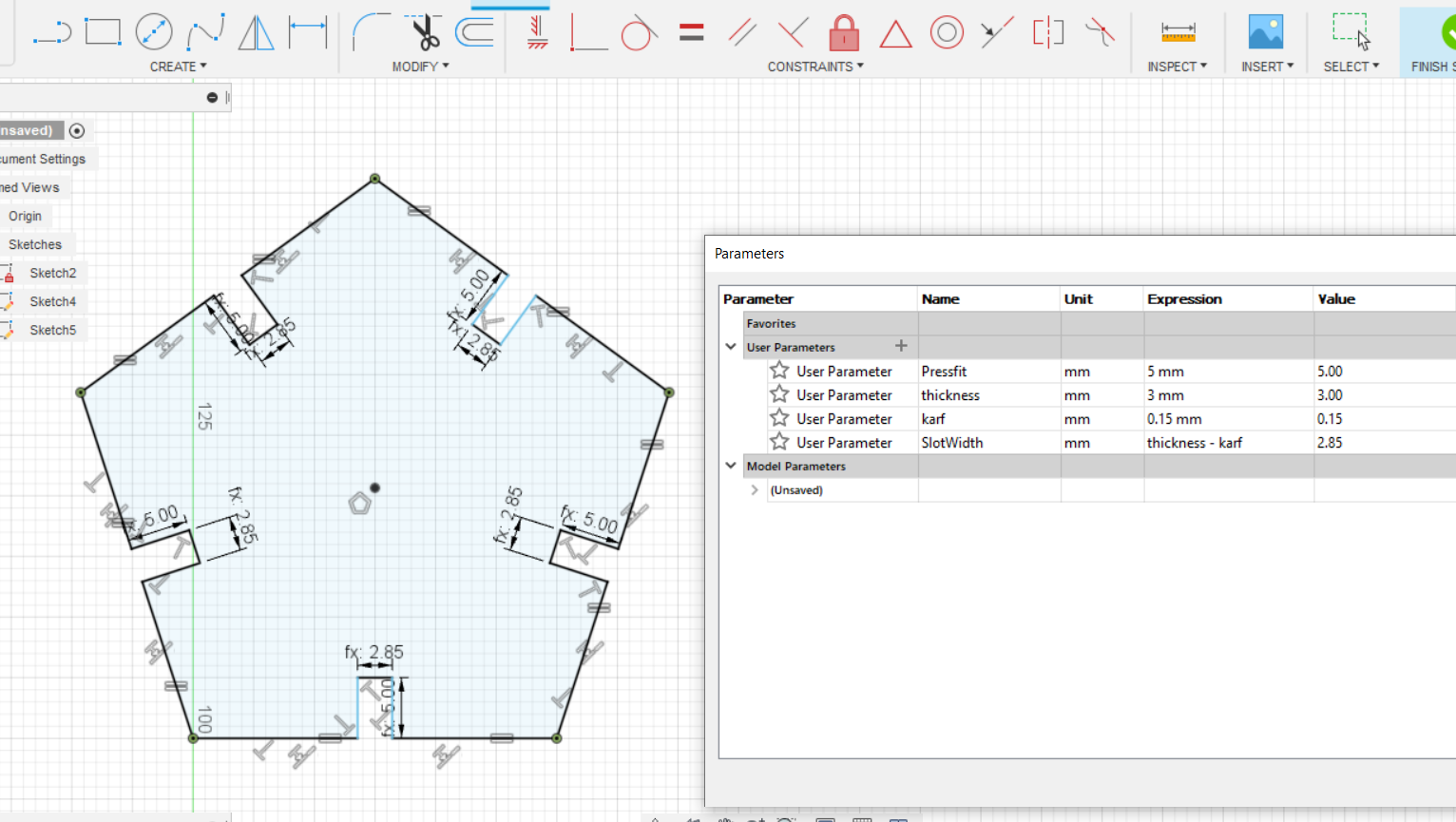
The joints are taken care the angle of 138° and 142°. And for assembly making sure the recognition which one is which, I put the circle cut as a marker of Hexagon-Pentagon side component.
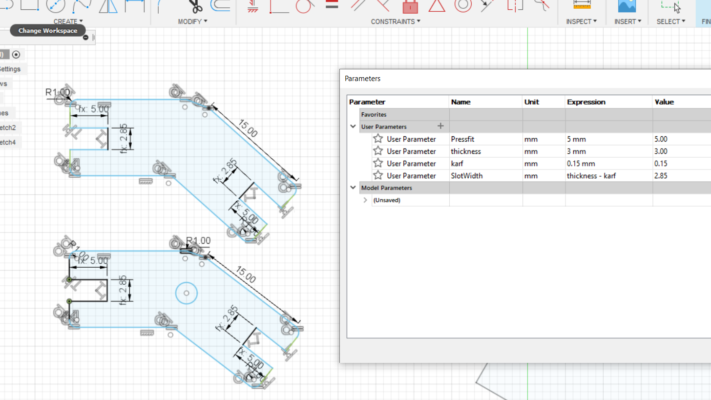
Parameters change can make the size change for each elements easily. (below is just example of different value in parameters, not for the production)
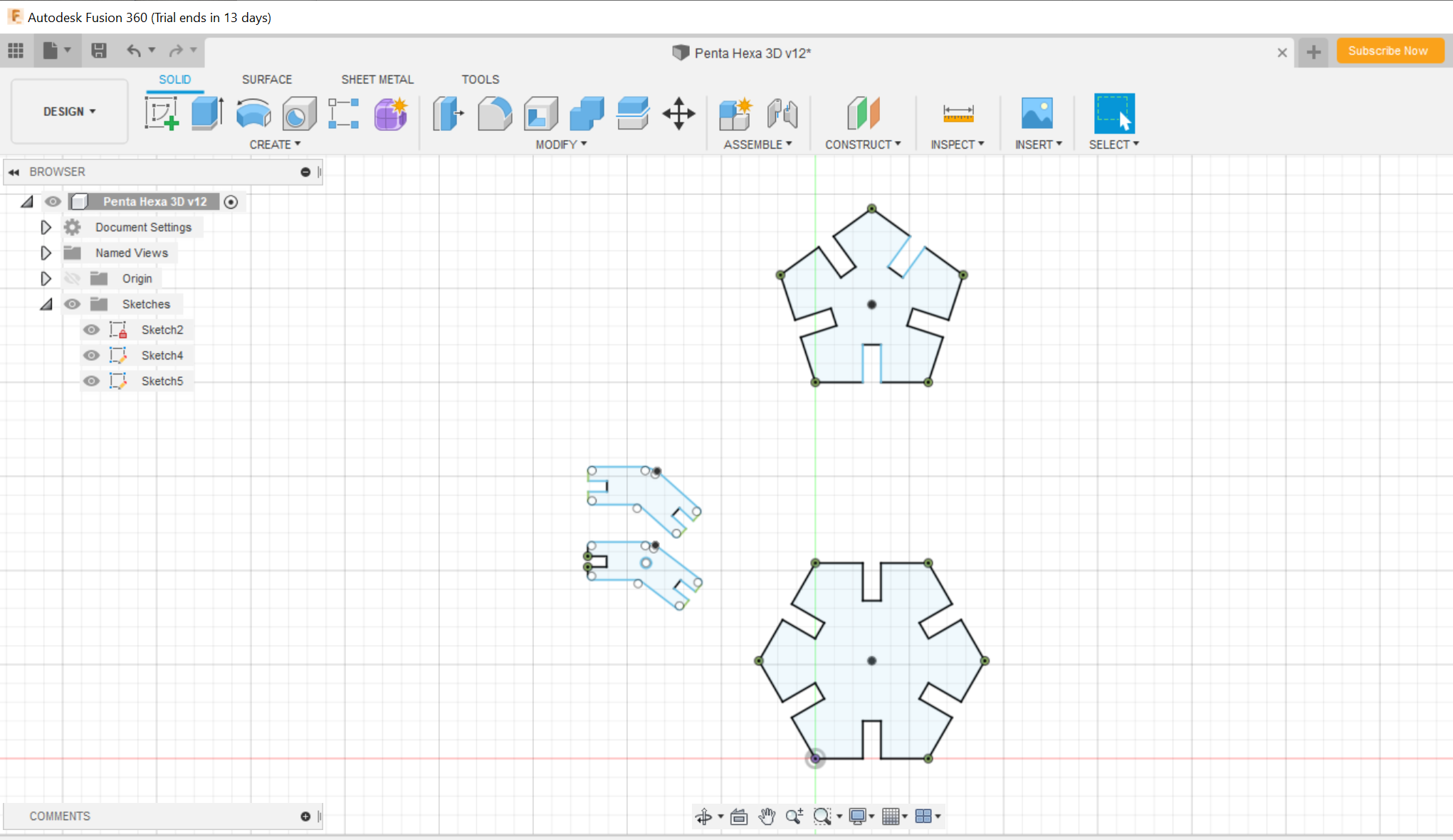
All parts design done.
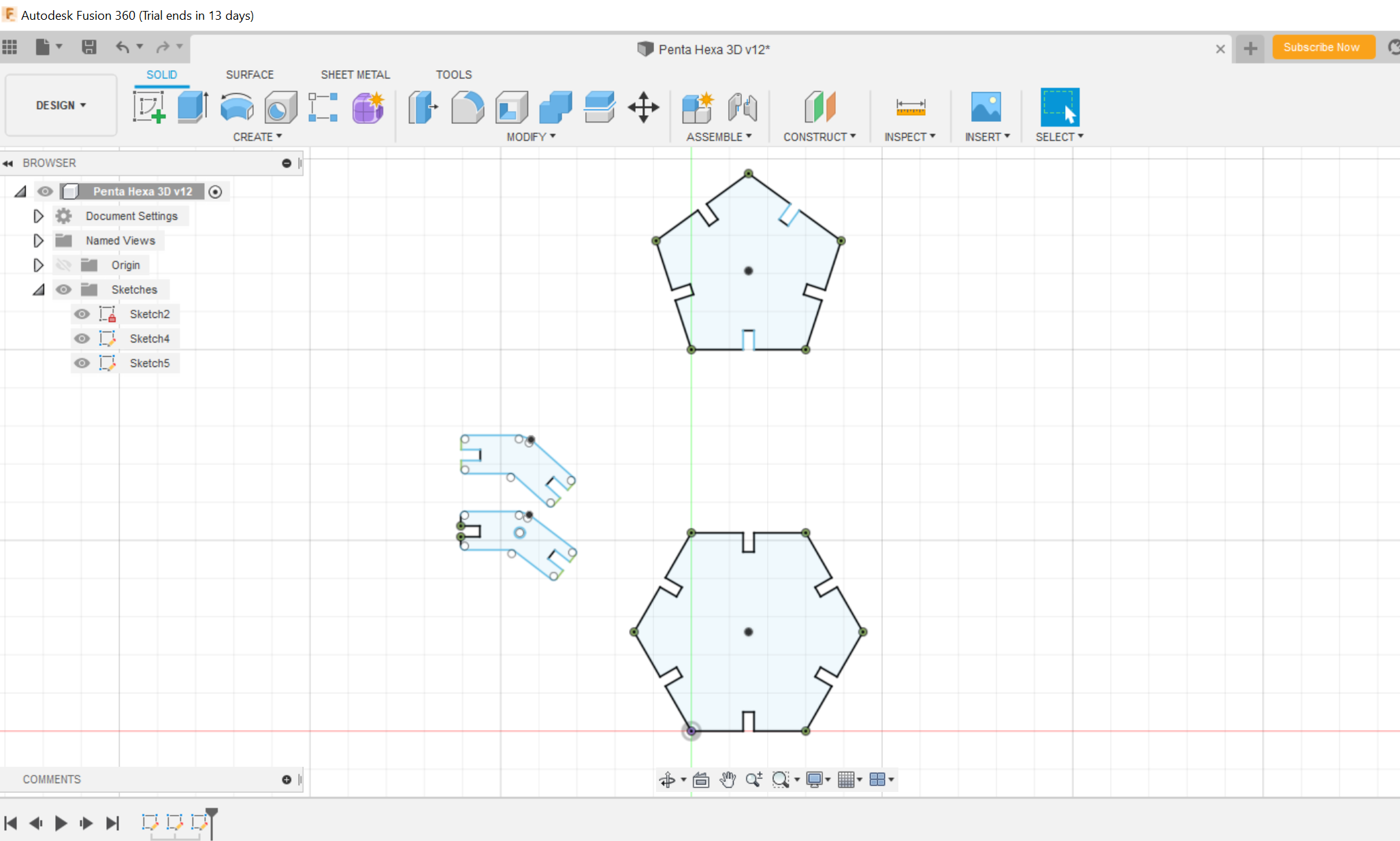
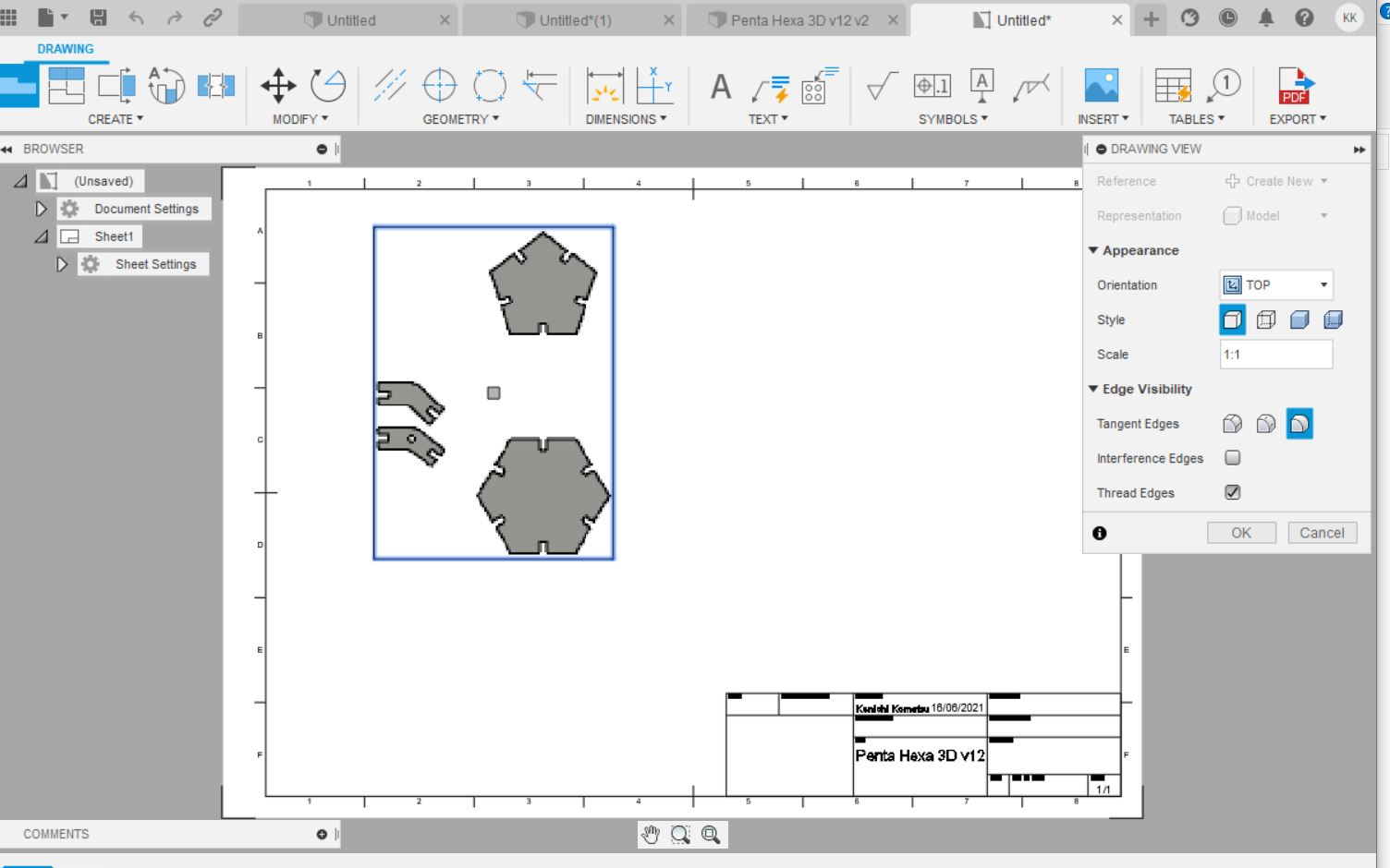
To print by laser cutter, the design needs to be converted to DXF file. First need to make 3D model by exclude.
Then plot by drawing, DESIGN -> Drawing -> from design and export by DXF format.
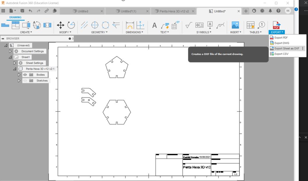
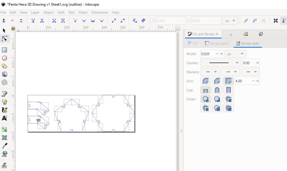
After got the DXF format, convert to PDF file by Inkscape.
Open by Inkscape, select all objects and follow these changes in Fill and Stroke,
- No paint in Fill(this case no graving)
- Chose black color with 100% in Stroke paint
- 0.02mm for Stoke Style
Then save by PDF format.
Cut by laser cutter using the PDF file.

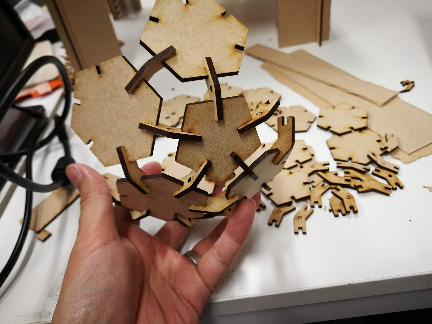
Basic shapes. I cut pentagon 12 pieces, hexagon 20 pieces and the joint of pentagon-hexagon 60pcs, hexagon-hexagon 30pcs.
Assembly.
Done! Good for room interior, satisfied result.
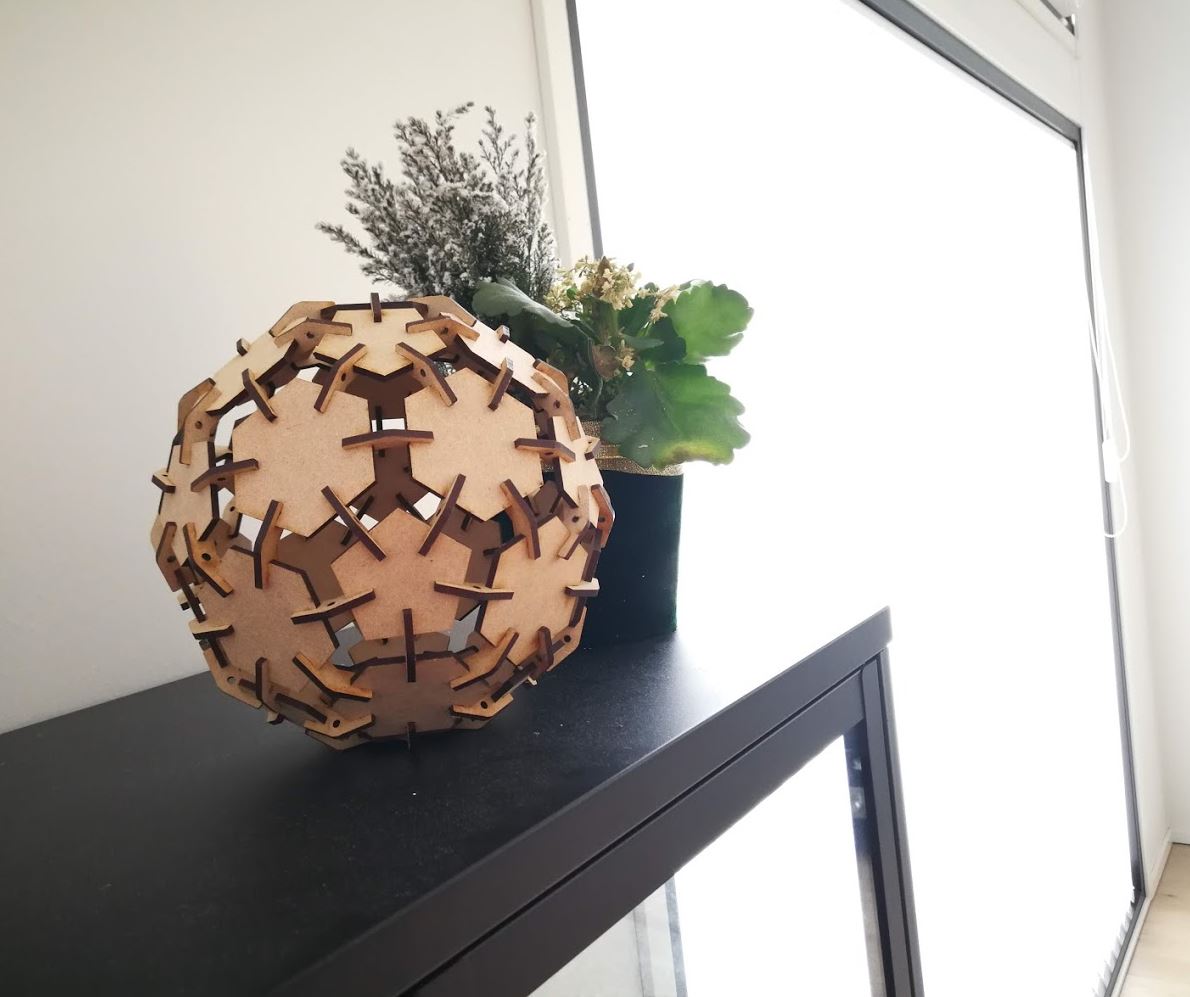
It was fun activity to use the design and laser cutter. However, I felt mistake to choose the football shape,,, it was challenging shape for design but also assembly.
4. Reflection, findings
-
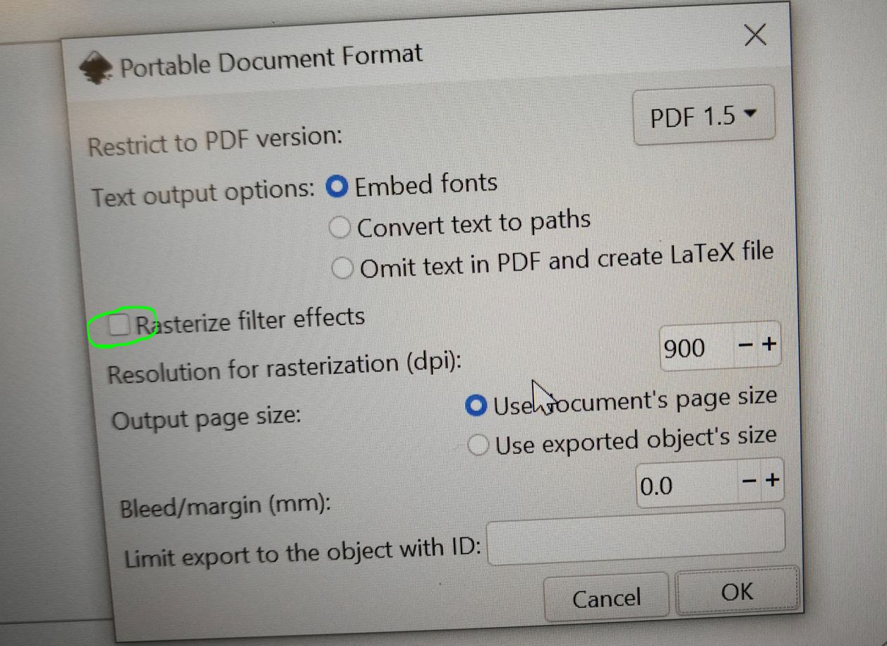
One finding in laser cut was, when producing the PDF file from Inkscape vector image, uncheck “Rasterize filter effects”. If check this, 0.02mm cutting edge also becomes engrave and cannot cut out.
-
One learning to use Fusion 360. After design the laser cut exercise, I made those to 3D design and assembled in 3D CAD. Then I found the mistake of kerf setting by other direction too much loose. It was good finding before the real cut of laser, saved some material and time for laser cutting.