
Computer-Controlled Machining
Homogeneos ResidenceLab is coming soon!
This week is very exciting and special for me. We are creating with my brother Homogeneos Residence Lab and now, we have a CNC Router ! I have previously explored woodworking in the traditional way with encouraging results. I have worked with plywood sheets, wooden slats and also with bamboo (my favorite n_n). Over time I have been very curious to explore woodworking digitally, that is why my first contact with a CNC machine for routing work on a human scale was at the Fab Lab iFurniture, where I could learn basic and not so basic things. of how to operate a CNC and the "crystal rules" in terms of design and tips so that you get a good job. So; this week I put my neurons to work, I remembered and re-learned about the whole process and was able to share these experiences with the team.
Plywood table design by me
Case for Wine design by me
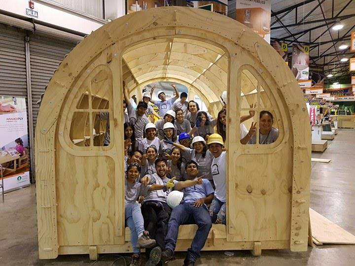
Team iFurniture
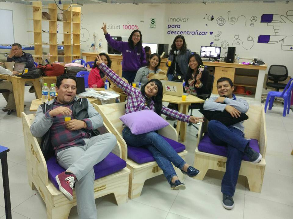
Team Fab Lab Peru
Week 7 Assignment
📆 March
Moving home [x0,y0,z0]to "Detonador Space"
For this assingment, we have moved to a space located in the district of Barranco, Lima-Peru. It's called Detonador Workshop, and it's Jose Luis's space , my older brother. Several activities related to art and architecture operate here. Barranco district is located on the coast of Lima, next to the sea, a place full of cultural, artistic life and tourist activities. In our usual laboratory Fab Lab Lima, we don´t have a CNC Router to cut wood and we don´t have enough space to carry out this type of task. Here, we have many tools for wood and metal work, plenty of space and we are outdoors for better sanitary conditions.
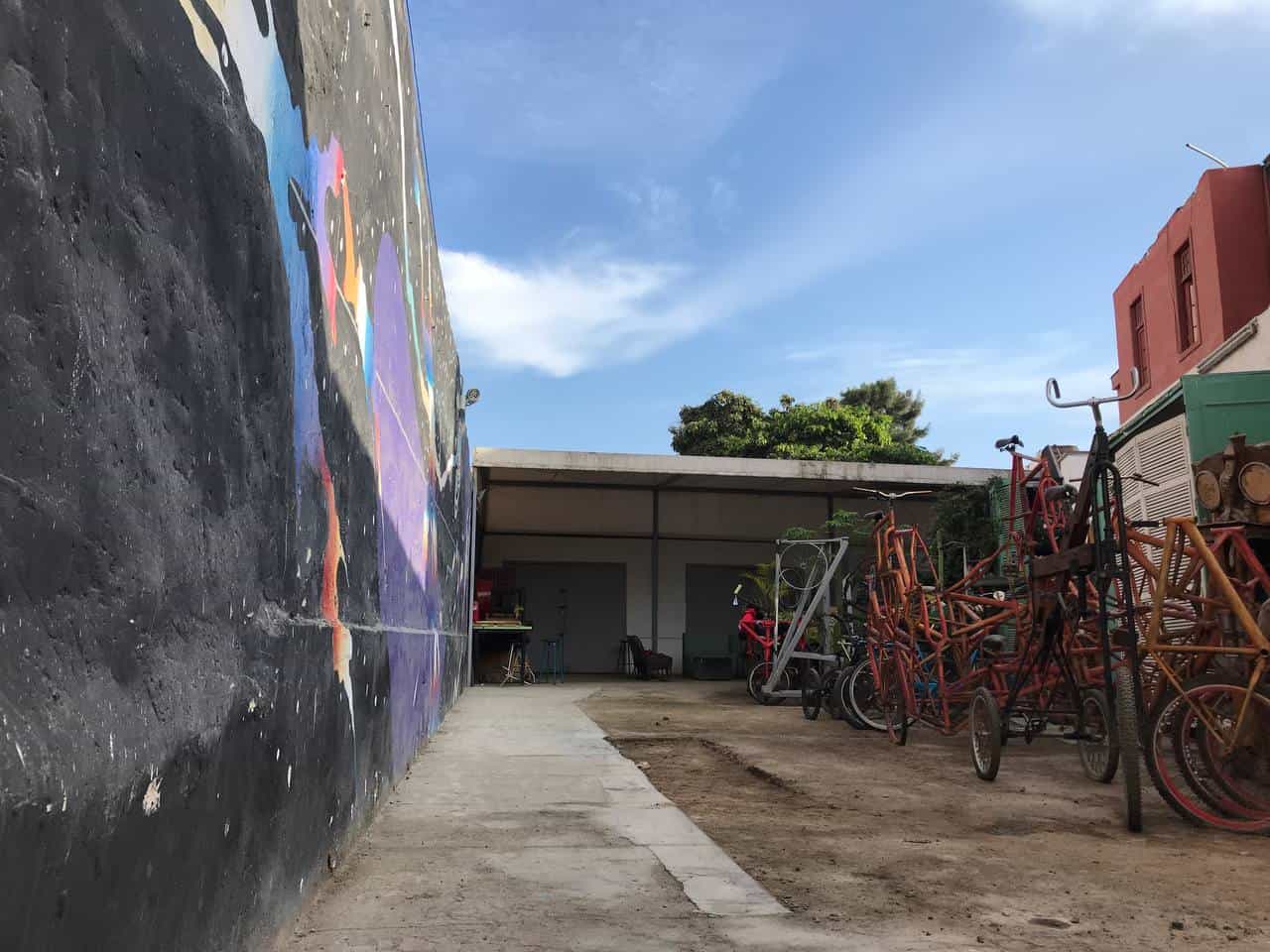
Detonador Space
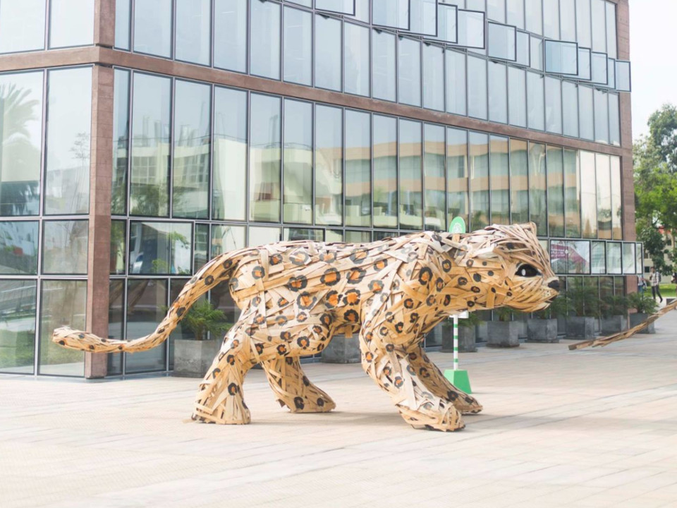
"Otorongo XL" _Detonador

XL Bycicles_"Human Motor" Performance
I had a half-assembled CNC Router at home, I mounted it in the car and took it to Detonator. Now we have a medium CNC that we are going to implement to take on this challenge. So together, with Mayra Ascencio, and the Fab Lab Lima Team we got down to work!
First, I designed the table on which we were going to put the CNC Machine. I designed it in the class of week 2: Computer-Aided Designed, (👉here you can see its development). I used Rhinoceros and then cut the pieces in 18mm Plywood. Already in the workshop, we assembled it and installed a slaughter table, for this I bought a MDF-grooved board and sectioned it into several parts. So we have 4 pieces to sacrifice!🤩
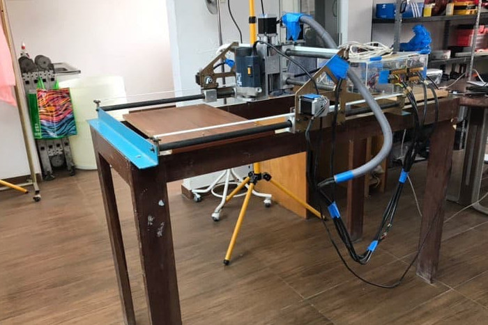
CNC by parts at home
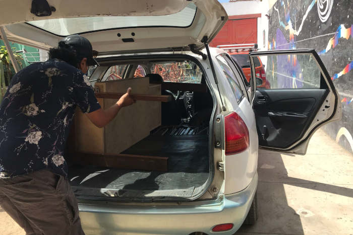
Transporting the CNC
Design table_Rhinoceros
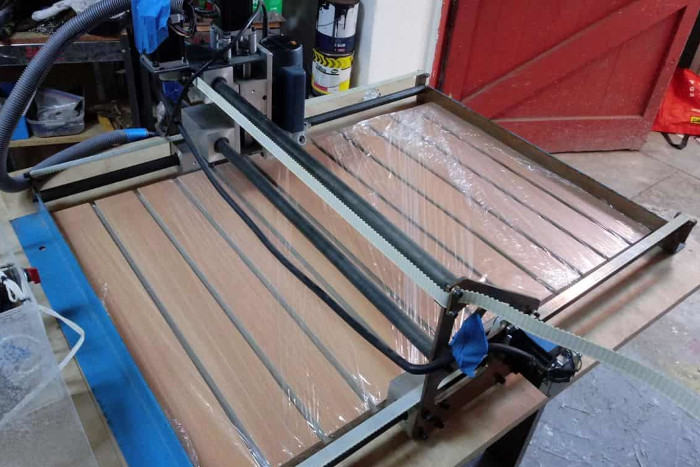
Setting up the CNC
Homogeneos Residence Lab is a project under construction housed inside the Detonator workshop. It is a digital manufacturing laboratory as well as a traditional one. This space allows the artist, scientist or creator, national or international, to carry out a residency to experiment on the subject they want. At this residency, the emphasis is on providing follow-up and support during the resident's creative process. The resident will finally decide whether or not to expose their research. This space aims to provide the community with a valuable exchange of knowledge between cultures. We are carrying out the implementation of this laboratory right now, which will have CNC cutters, 3D printers, laser cutters, tools to make sculptures, electronic components and even audiovisual equipment.
The CNC Router Hybrid 000-490
Two years ago, we acquired this CNC machine, it is approximately 20 years old and it was built as part of the thesis of the electronic engineer Jorge López, we thank him very much for his contribution. It is based on a manual router, motors and belts. The entire electronic system is very old and some parts have been replaced by modern parts, such as the motherboard. Now it works based on Arduino, but the drivers are the original ones, huge! So we have a great hybrid going.
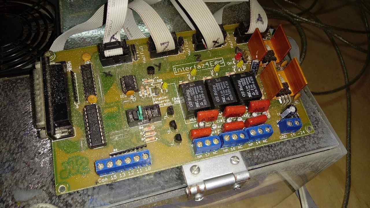
Old electronic board
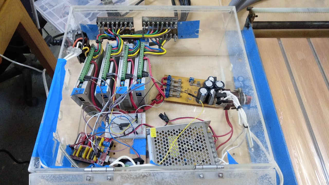
Old Drivers + Arduino
The table with machine
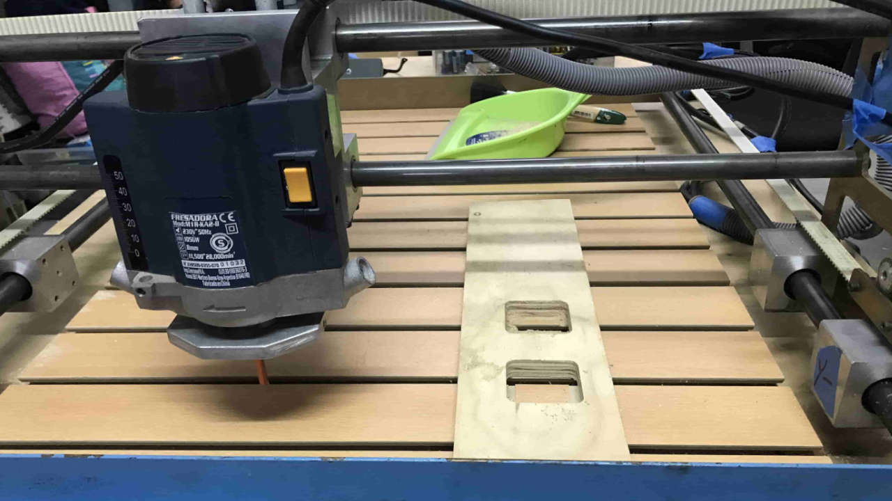
The Router
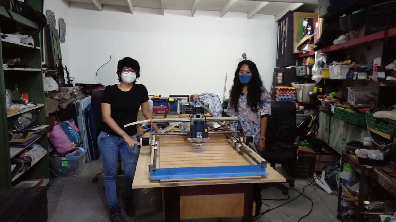
The lab Space
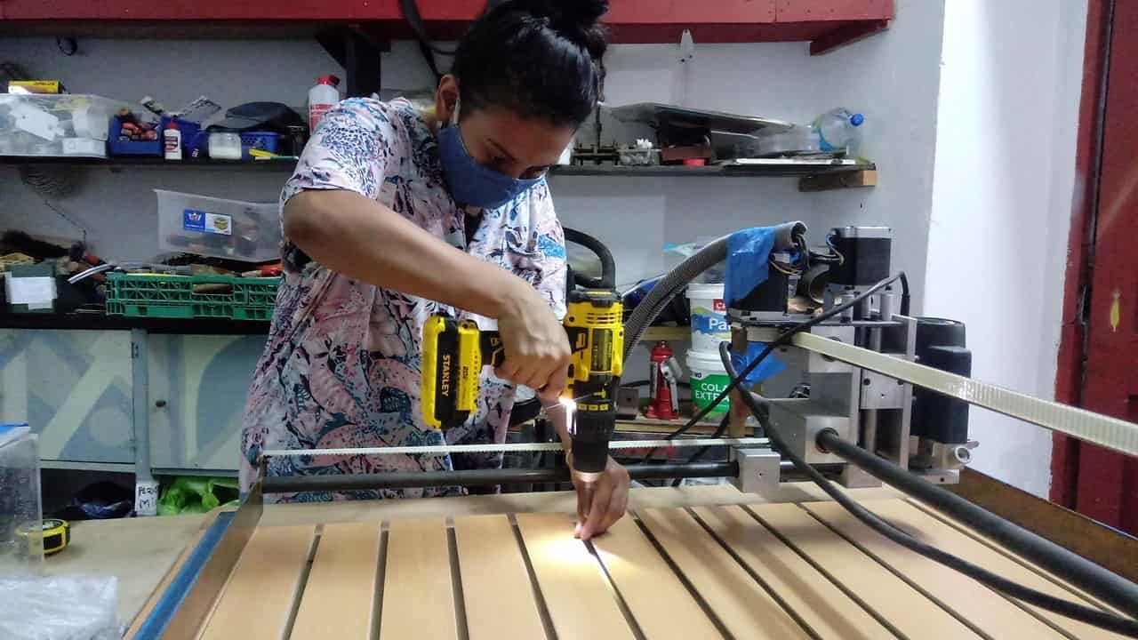
Preparing the machine
GroupTask
The group assignment this week is about testing our machine, test runout, alignment, speeds, feeds and tool paths and we have to document this entire process. Next we will see the arduous process that we take to start the CNC and have our first test. For this we needed to get many things, for example, the cutters for cutting, the programs to manipulate the machine, the material that we would cut (wood), a vacuum cleaner, screws, screwdrivers and many more tools that we would probably find in the workshop Detonador.
Recognizingthe GRBL
We'll start with the perse machine. A year ago I had installed an Arduino UNO alongside a CNC Shield Board, which already had the GRBL loaded on the board. The GRBL is open source firmware that runs on an Arduino UNO that converts G-code commands into step-by-step signals. Our machine works based on 4 stepper motors, in the three axes X, Y, Z and has an extra motor in the X axis. Unfortunately none of our laptops recognized the Arduino and we could not control any axis, 0 movement. To solve this, we had to update the USB port driver on all of our computers and we were able to recognize the machine.
Components of our CNC:- 12v and 15A power source
- 1 x CNC shield
- 1 x Arduino UNOR3 board
- 4 x original drivers.
- 4 x stepper motor
- 1 x USB cable
Configuración GRBL
Error: Can't open COM PORT
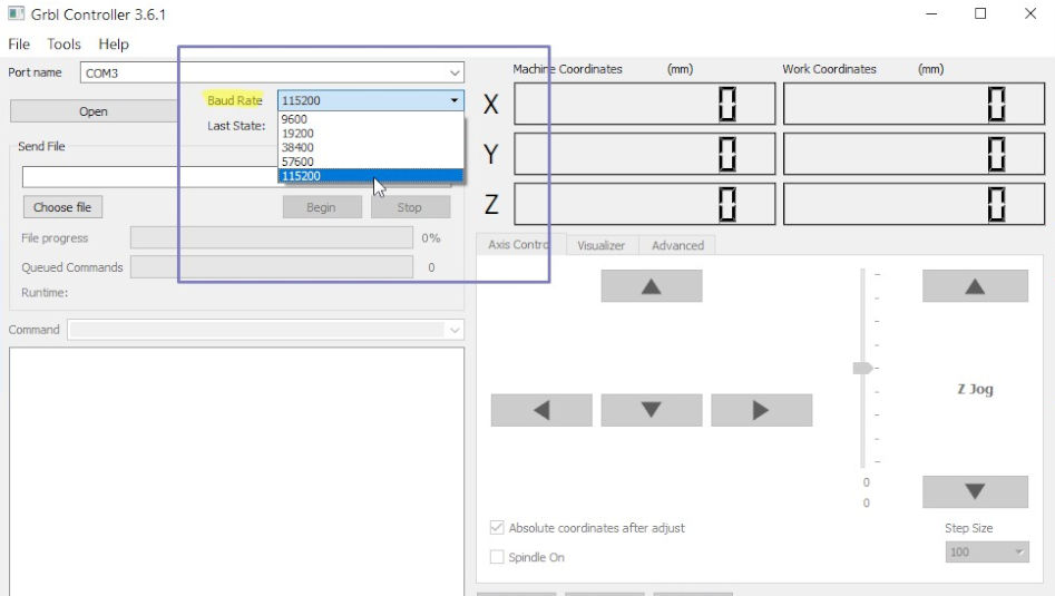
Baud Rate GRBL Controller
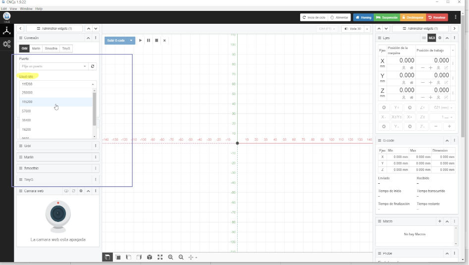
Baud Rate CNCjs
We tested with the CNCjs program and with the GRBL Controller program. Finally, after updating the USB port driver, the two programs were able to recognize the machine. It is very important to select the value of 116500 in the Baud Rate Parameter (this is the appropriate value for our machine) so that the CNC can be recognized correctly. To update the COM port driver, we use an Offline method. Download the driver PL2303_Prolific_DriverInstaller_v1210, install it on the laptops, and then you must go to Device Manager >> COM Ports >> Select the corresponding port (COM3 or COM1), right click >> Update Driver, manually choose Update the Version 3.3.11. This will update the COM port and when opening the GRBL Controller if it will recognize the machine.
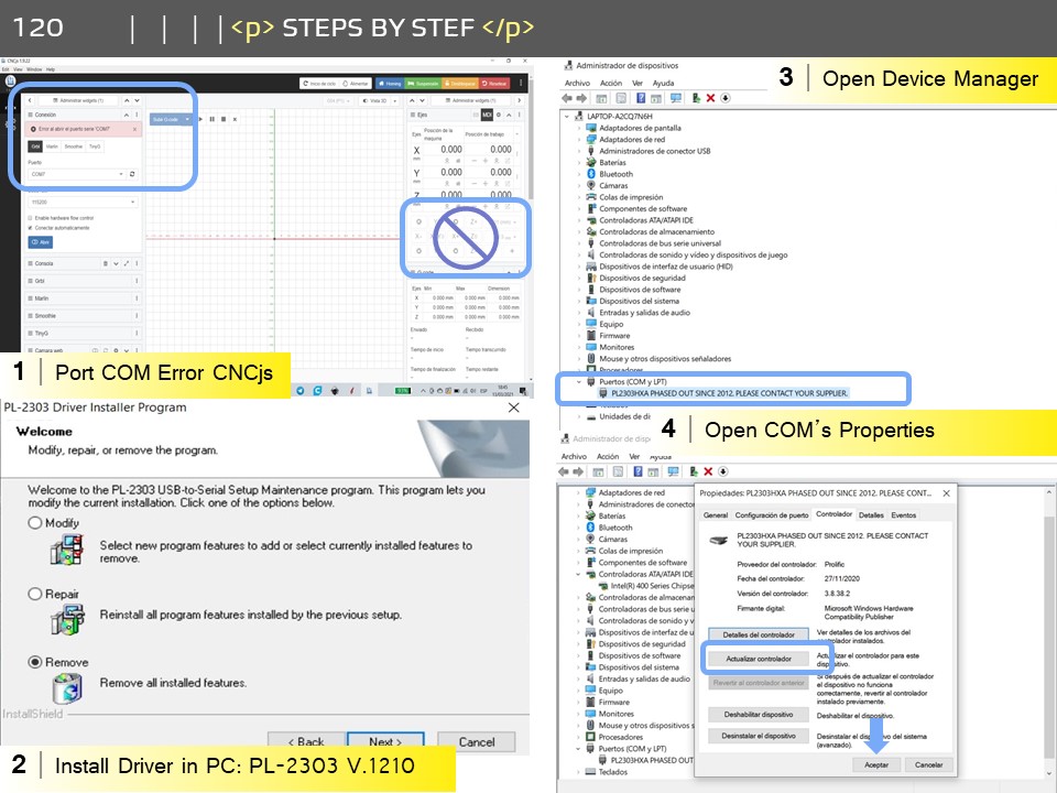
Installing Port COM's Driver
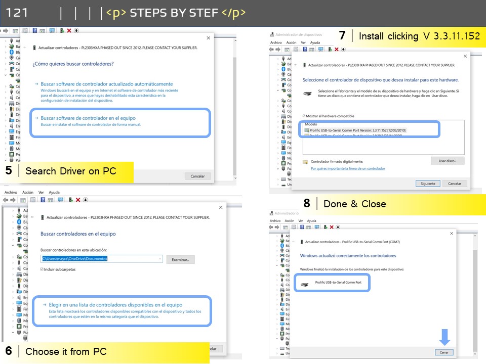
Installing Port COM´s Driver
Testing& Drills
When the driver is already installed. We went on to test the different softwares that we can use to control the axes of the CNC machine. Here at Homogeneos Lab we work with a built-in, high-performance open source CNC milling controller and g-code analyzer written in optimized C that will run on a direct Arduino called GRBL Controller and we had previously used the CNCjs, other software from open source that serves the same functions. So we decided to try both.
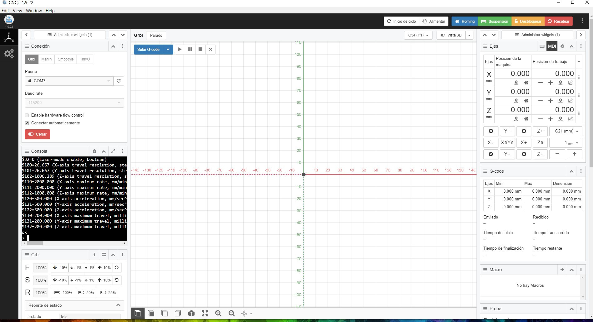
CNCjs
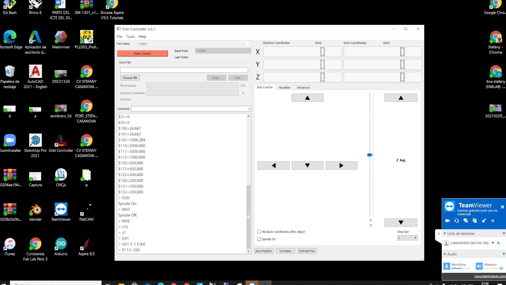
GRBL Controller
Drills
When the driver is already installed. We went on to test the different softwares that we can use to control the axes of the CNC machine. Here at Homogeneos Lab we work with a built-in, high-performance open source CNC milling controller and g-code analyzer written in optimized C that will run on a direct Arduino called GRBL Controller and we had previously used the CNCjs, other software from open source that serves the same functions. So we decided to try both.

Milling research
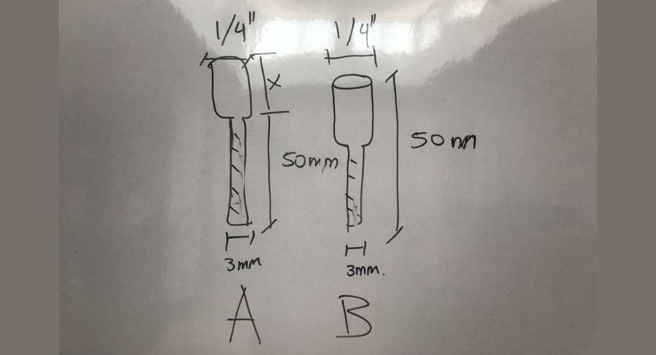
Measurements required for milling cutters

1/4” x 6.3 mm truper milling cutter.
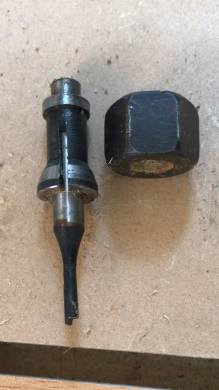
Collet
Testing the machine
The first thing we did was to generate two small rectangles of 40x40mm. to see the accuracy of our milling machine in terms of straight cutting and to see the precision. The final pieces were 40.03 mm on each side, which is the right size for an accurate assembly.
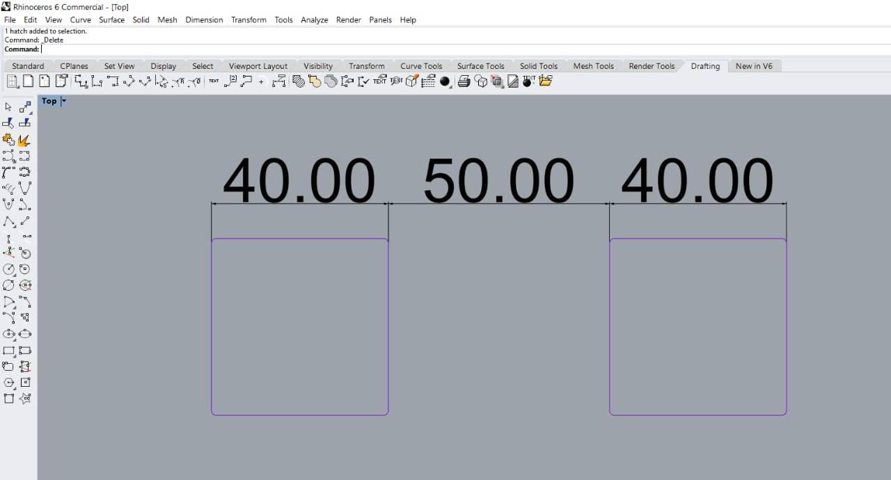
Rhinoceros design

Cut pieces
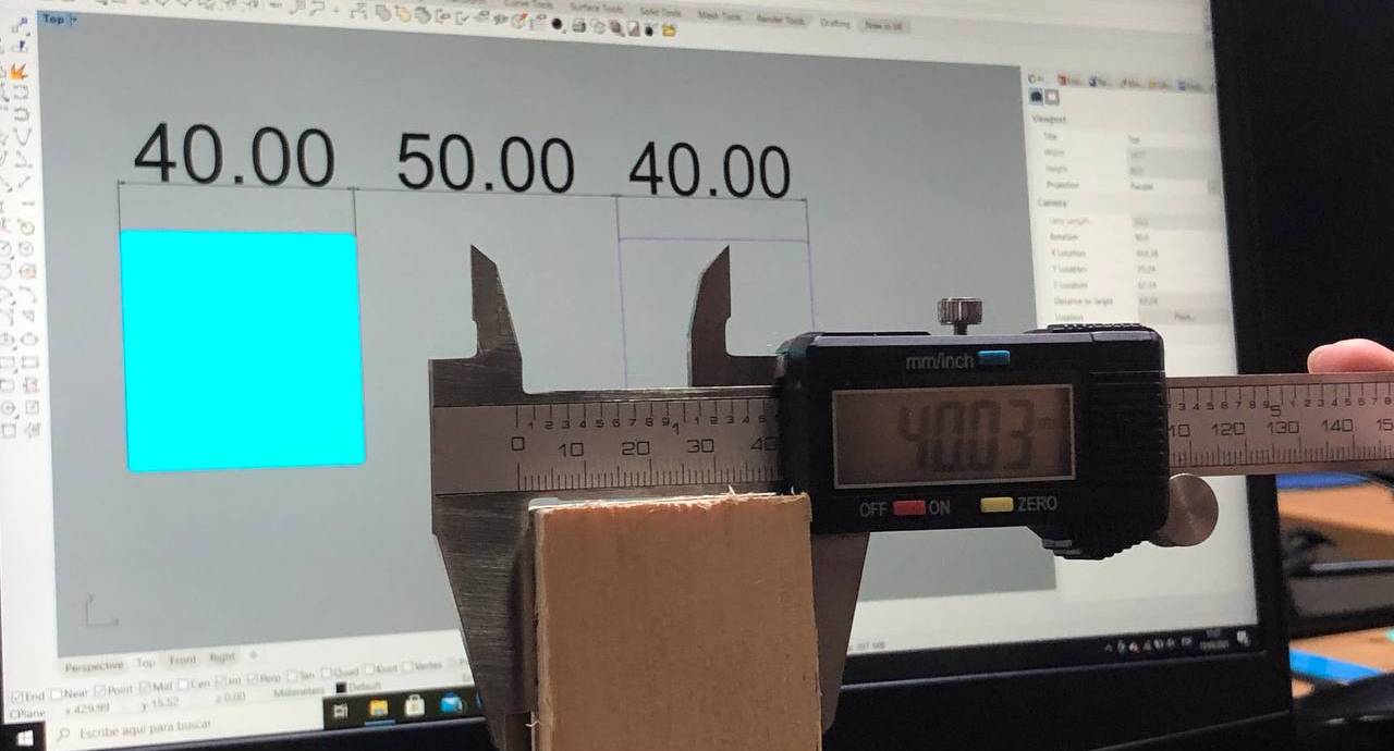
Good cutting precision

Measuring
Joint test
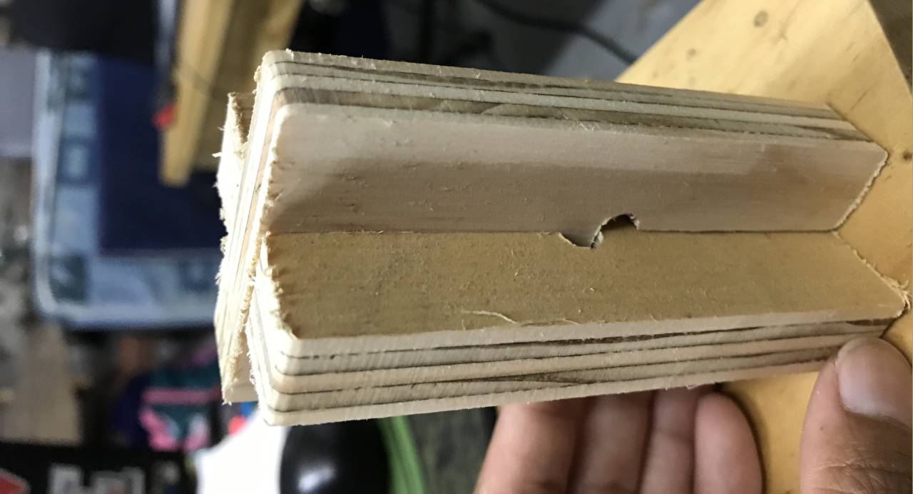
We designed a first joint exercise, it is a simple fitting where we wanted to test how we would fit our 15 mm. wood, for this exercise we used recycled wood and we designed the first test objects in Rhinoceros, this object measured 50 x 10 mm. and it was a 15 mm. thick wood, we used the dog bone technique with a diameter of 7 mm. because our milling cutter was 6.3 mm. and we rounded all the corners to ease the milling cutter path. In addition, we left a tolerance of 0.5 mm. in the total width of the socket to check the kerft what was the final measurement of the cutter and if the socket was going to be efficient.
Test cut for joint

Two-piece design for testing
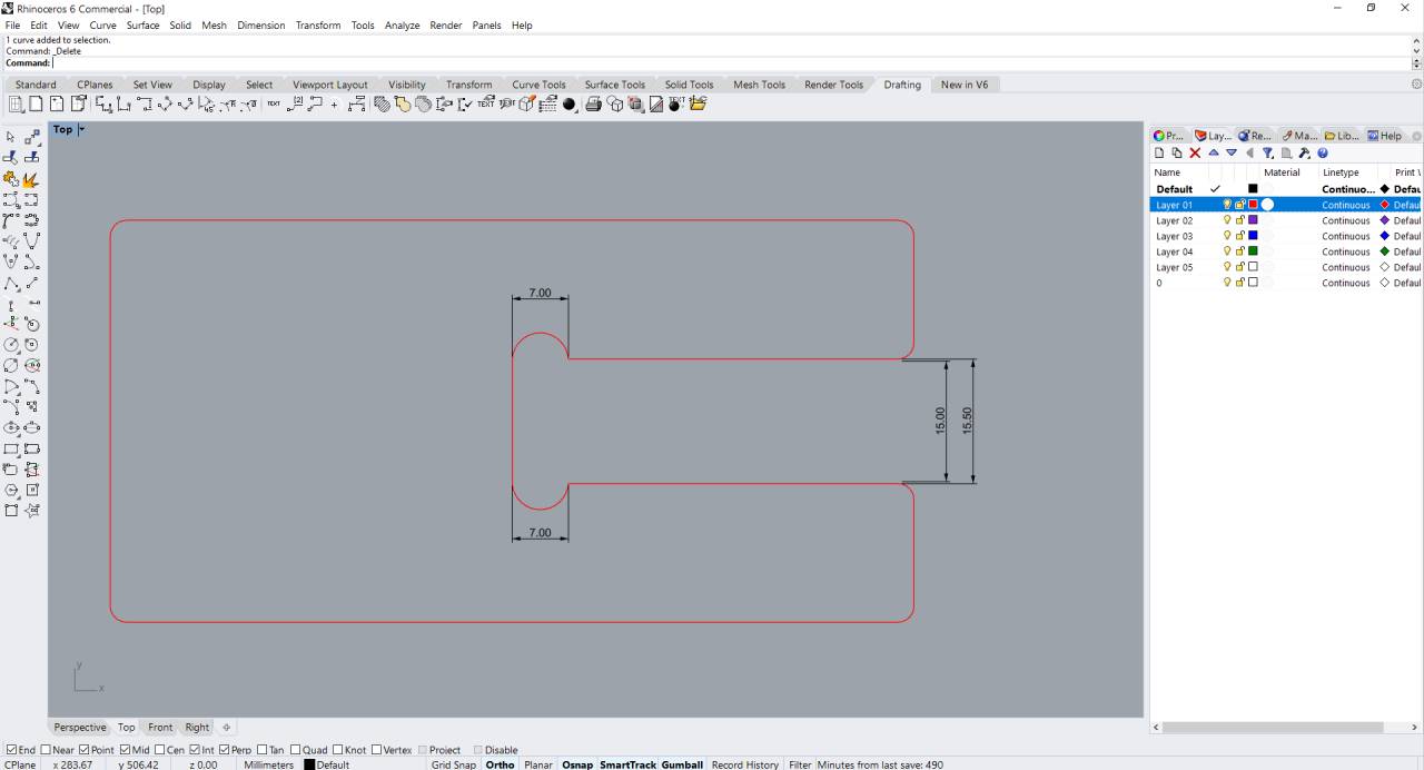
Piece dimensions

Finished cut
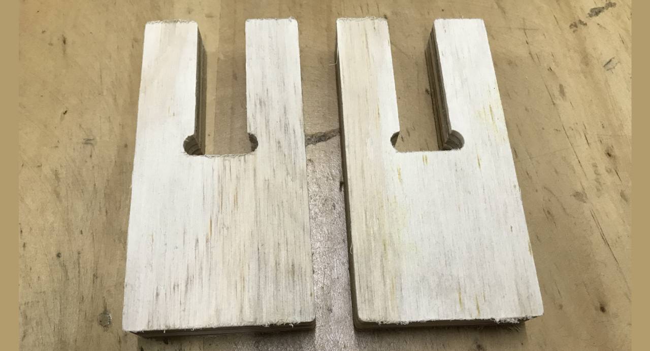
Ready parts

Efficient joint
final joint
IndividualTask: Skylight design
After testing our machine and the joint, we decided to design something big that is something useful for the space where we were working, the space where we were working is an old house in Barranco and these houses used to be illuminated by the top with windows in the roof, these windows are called skylights and we decided to design a skylight to cover the roof of the workshop space where we were working. As our machine is small whose cutting area is 66x46.5 cm. we decided to make a fragmented design of the pieces and have a lot of ingenuity to make the skylight.
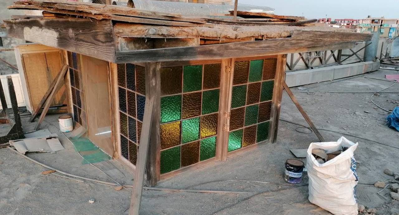
Example of skylight from the outside
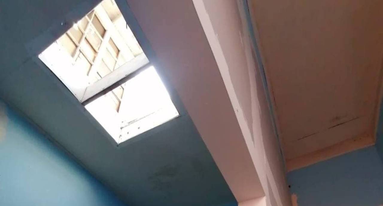
How the skylight looks like from the inside
After examining an example of a skylight in an old house, we proceeded to measure the dimensions of the hole in the roof of our workshop, with the purpose of designing a customized skylight adapted to that space.
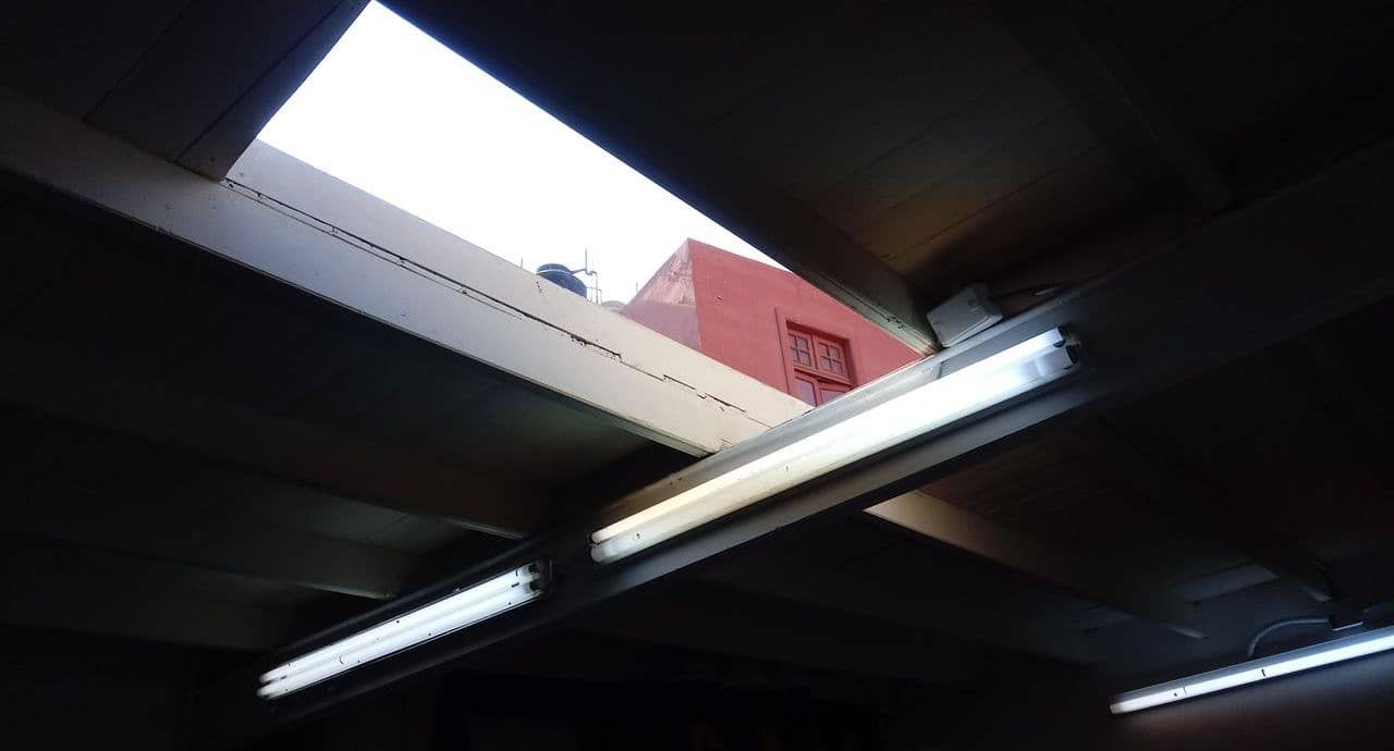
Hole in the roof of our workshop

Skylight dimensions
The skylights have the characteristic of having windows on the sides through which there is a cross wind circulation where the hot air rises and exits to the top of the house, so it is cooled. The top is roofed and the light enters horizontally, for this reason the design has windows on the sides and roofed upper parts.
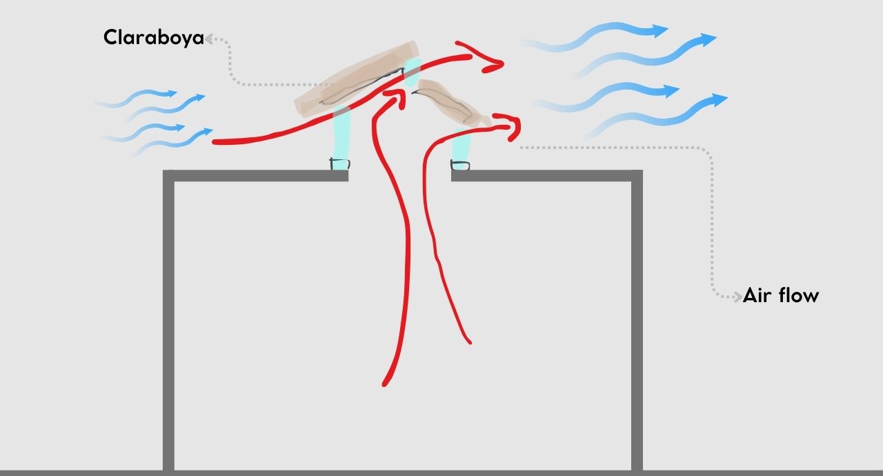
Wind flow study
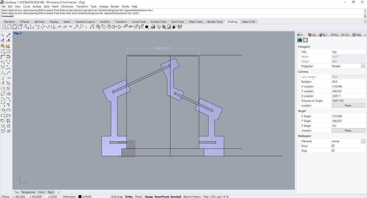
First pieces

Skylight skeleton
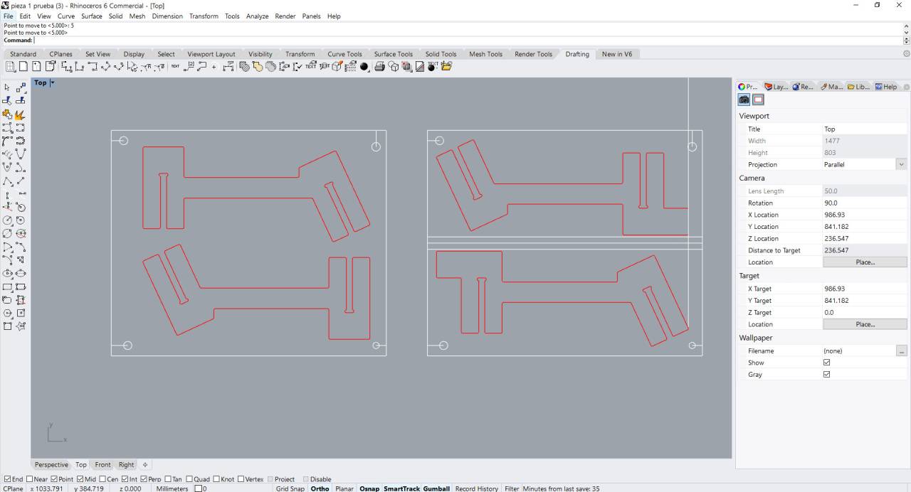
First design to cut
First cuts
Before developing the design further, we create the first cuts. For these first cuts, thanks to iFurniture we were able to have a lot of material to make the pieces, this material was recycled. In this case, as our CNC is small, it was convenient to have the scraps to be able to use them with the dimensions we could work with. We use Artcam to generate the G-code and GRLB controller to manipulate the CNC machine.

Material received from iFurniture

Part 1 first test

Part 2 second test

Part 1 first test

Part 2 second test

Multiple parts
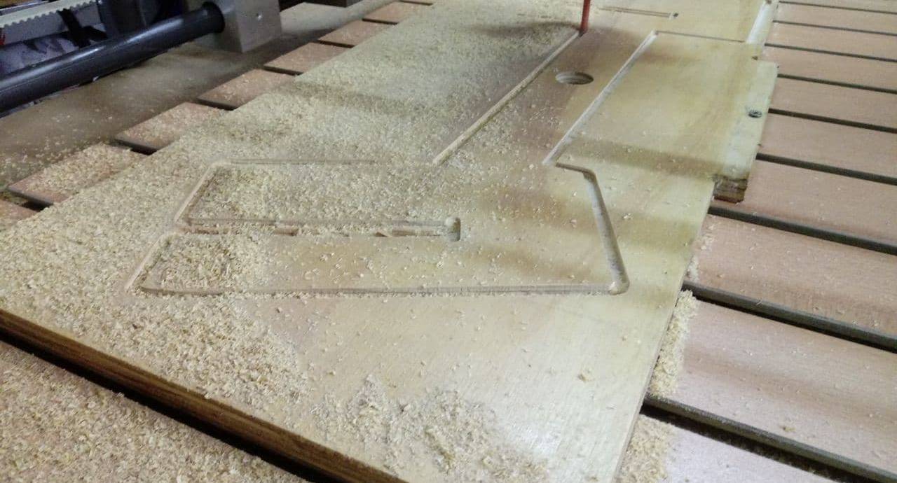
Piece cutting
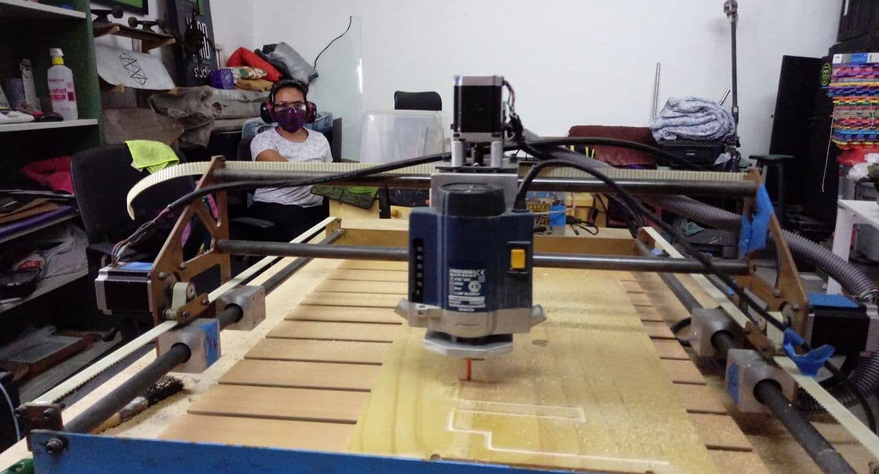
Cutting the piece
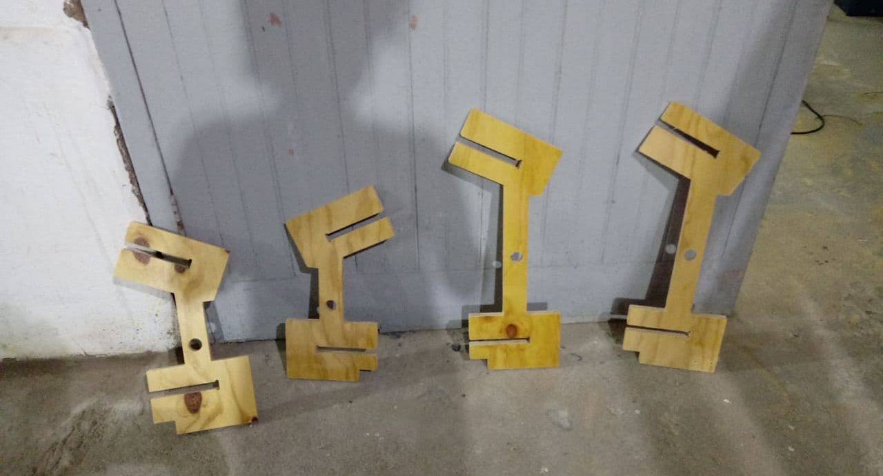
Pieces ready
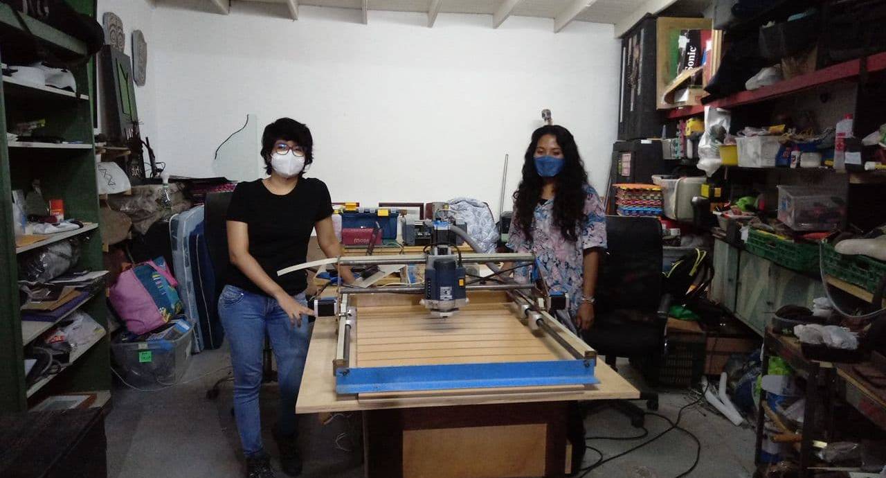
Working as a team
Cutting the piece
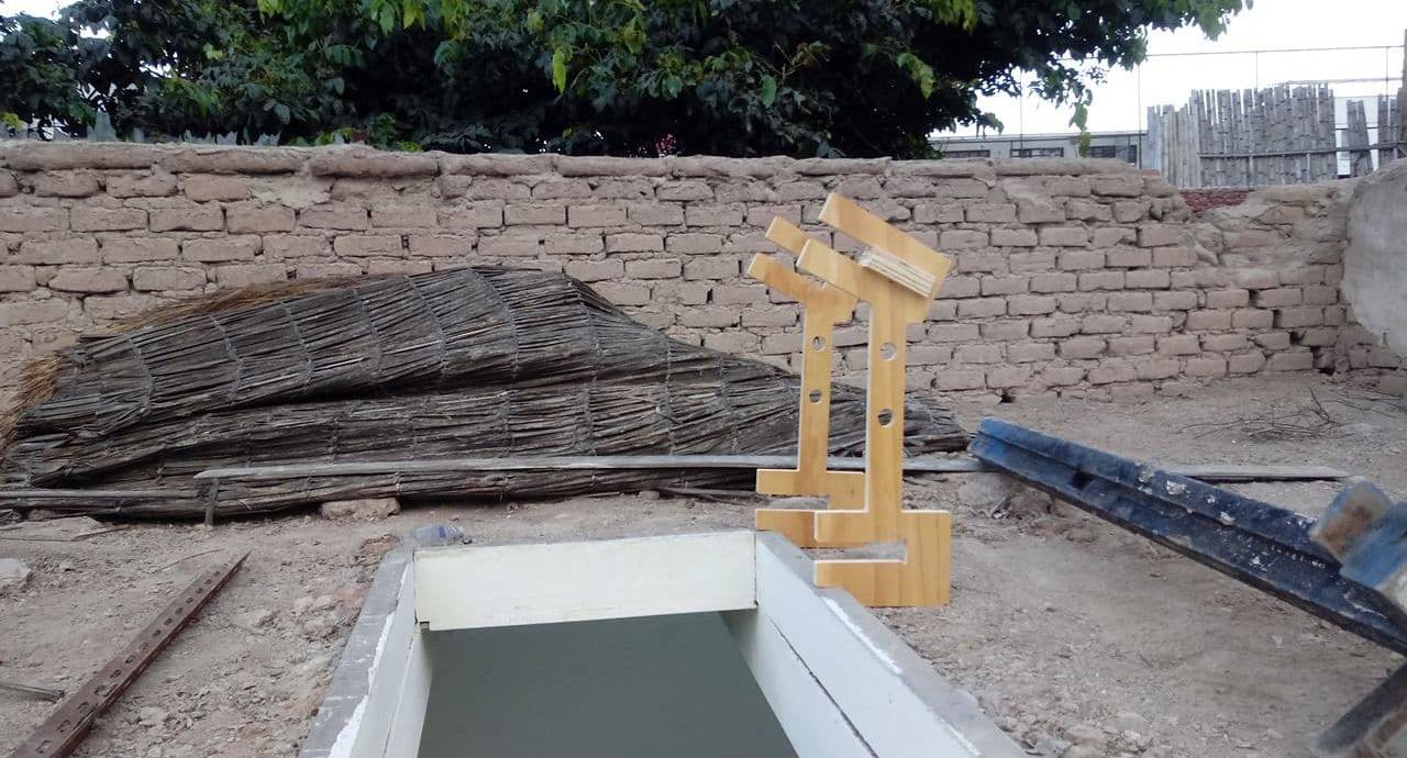
Structure test
Improving design
After the first tests we could see some flaws in the design such as the angles of the roofs, the joints, the union between the pieces and the sequence of assembly. For this we proposed improvements in the design such as the angles in the roofs, the improved assembly sequence, the different heights, the angles of inclination in case it rains, although in Lima it rains little, the overlapping of the pieces, the rotation of the window and all the considerations to take into account so that our design works well.

Roof angle, height of parts and vertical structure

Overlap design

Beam and roof analysis for skylight support

Skylight hole dimensions

Hingeless window system

Skylight parts

Skylight structure and skylight piecing

Dimensions of the recycled wood pieces

Classification of scraps by dimensions

Classification of the pieces in the final design

3D and 3D cutting file

Vector file for cutting
Cutting the skylight
To start cutting our skylight design we had to follow a process in different software, first the design was made in Rhinoceros, since our machine has a cutting area of 66 x 46.5 cm. the pieces were arranged each one in a piece of wood and then exported in DXF, because our CNC is small we could not cut more than one piece at a time. The next software we used was Artcam to generate the G code, at the end we used the GRLB Controller software to cut the parts. Due to the size of our CNC it generated an endless list of cutting files, however the task was accomplished successfully.
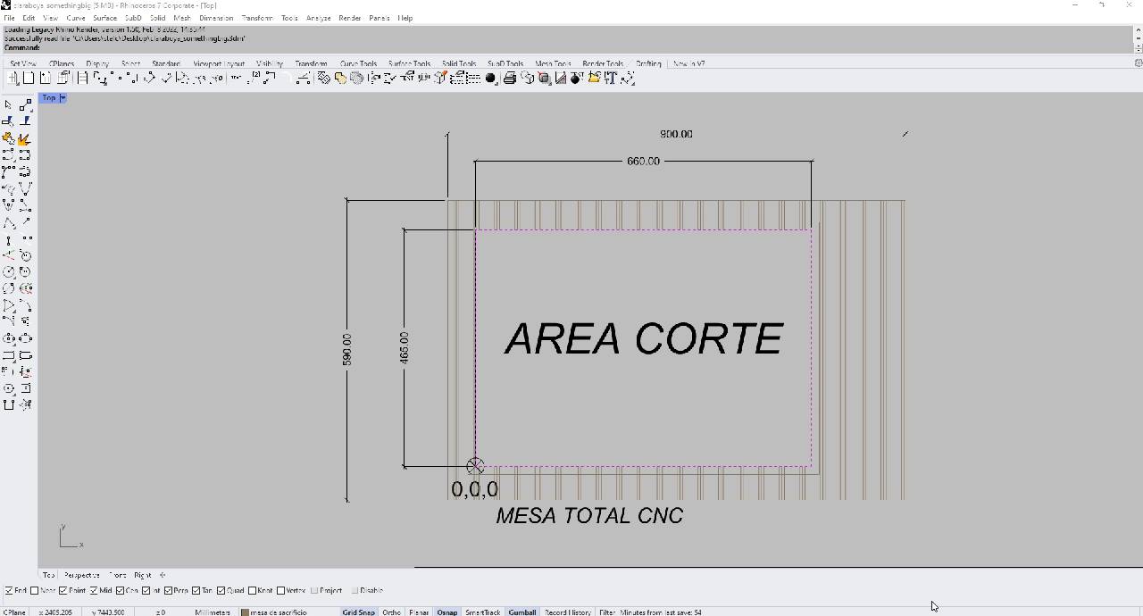
Cutting area
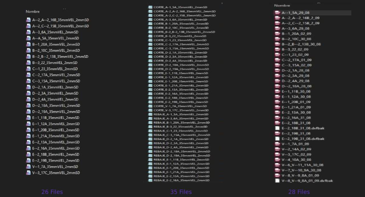
DXF, Artcam and G-code files
Roof cutting
To cut the roof was divided in two by the size of our CNC, for this we designed a piece with a rebate at the end so that it can be joined to its pair, in this way we obtained the piece 1a and 2a, this piece needed to be cut and rebate at one of its ends to half its thickness. To start the cutting we need to convert the .DXF file to G code using Artcam software, for this process the following steps were followed:

Export from Rhinoceros to .DXF

Artcam worktable configuration

Import .DXF file

Vector transformation, starting point 0,0,0

Area Clearance configuration

Truper milling cutter configuration 1/4“ x 6.3 mm.

Parameters for Area Clearance

Create G-code for area clearance

Create G-code

Cutting line configuration

Ramping move configuration

Material configuration (15 mm.)

G-code creation
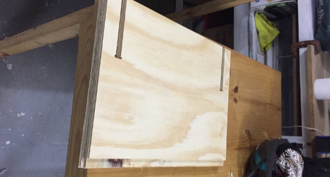
Piece with rebate
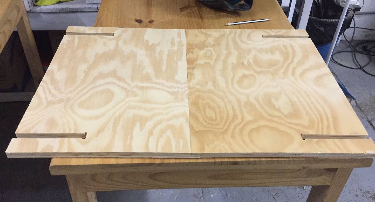
Joined pieces
Window cut
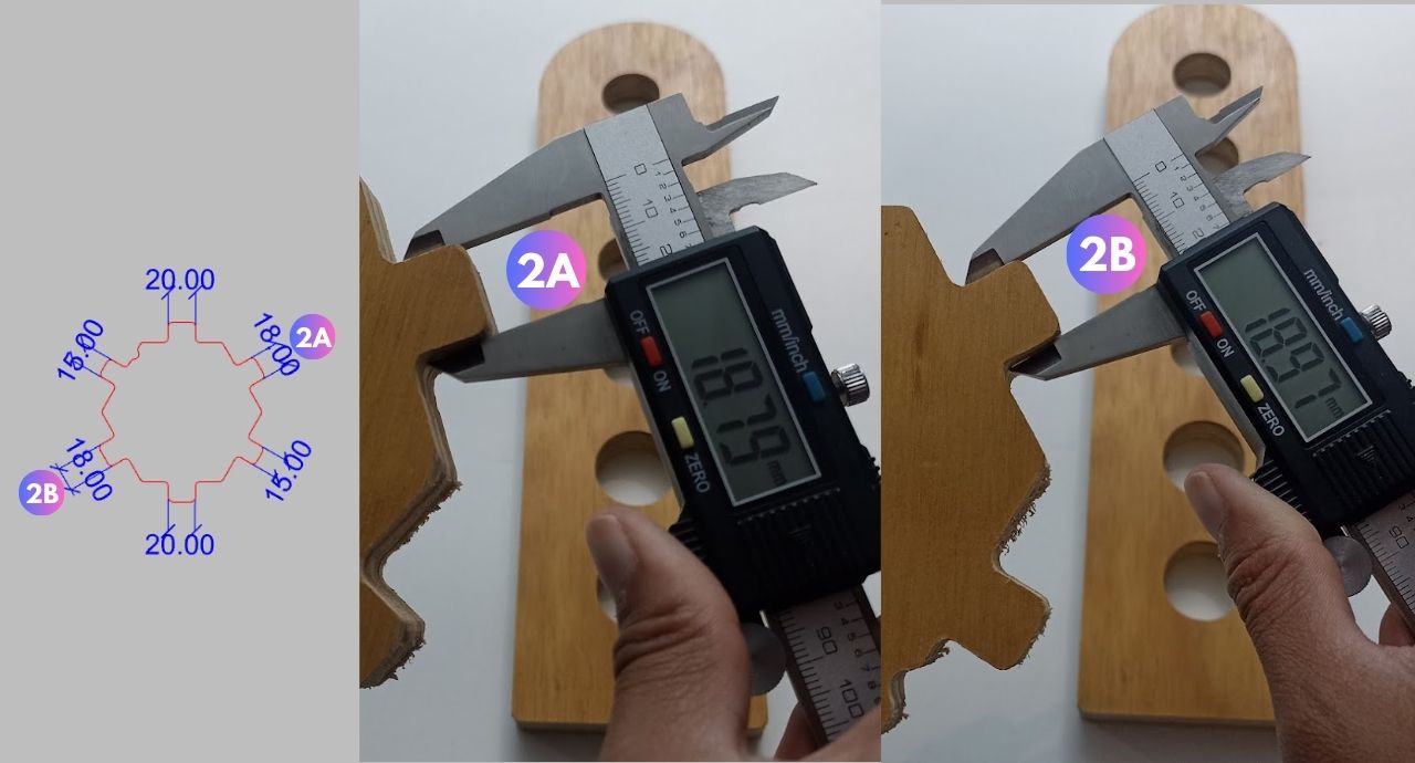
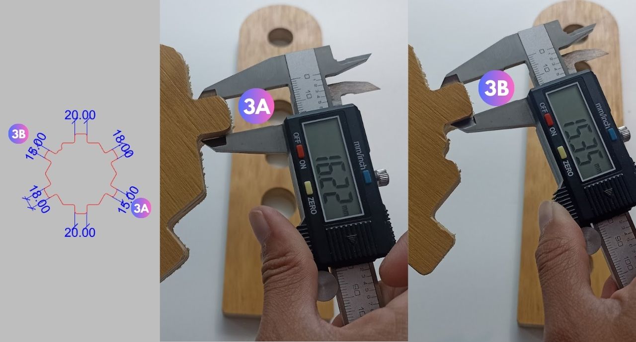
In order to cut the window, we first created a test file that allowed us to see which dimension had the best rotation and at the same time a smooth rotation at the window hinge and at the window axis.

Hinge test in digital woodworking

Hinge test in digital woodworking
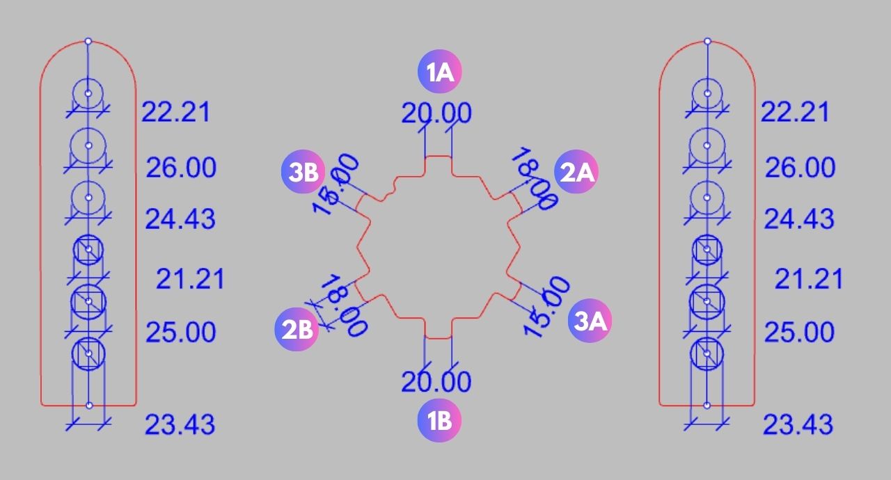
Proposed design dimensions
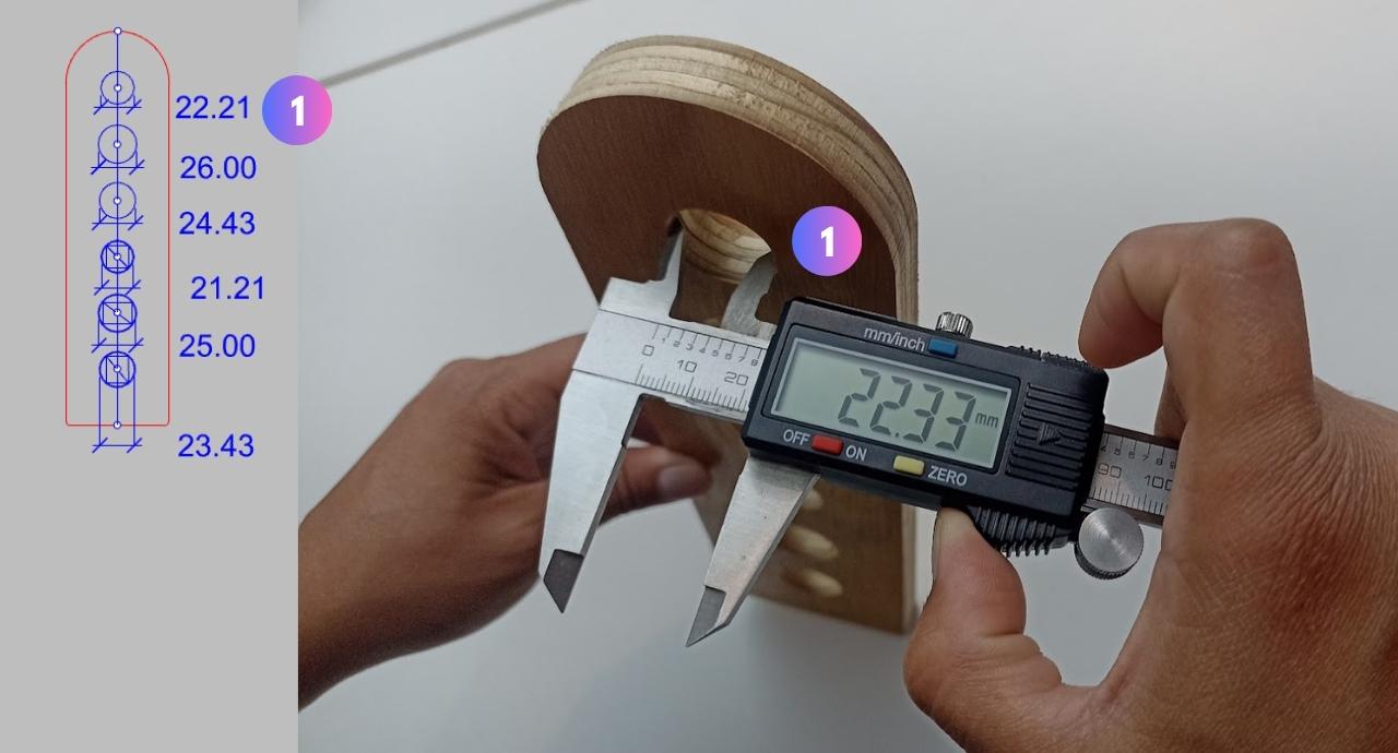
Resulting milling dimensions
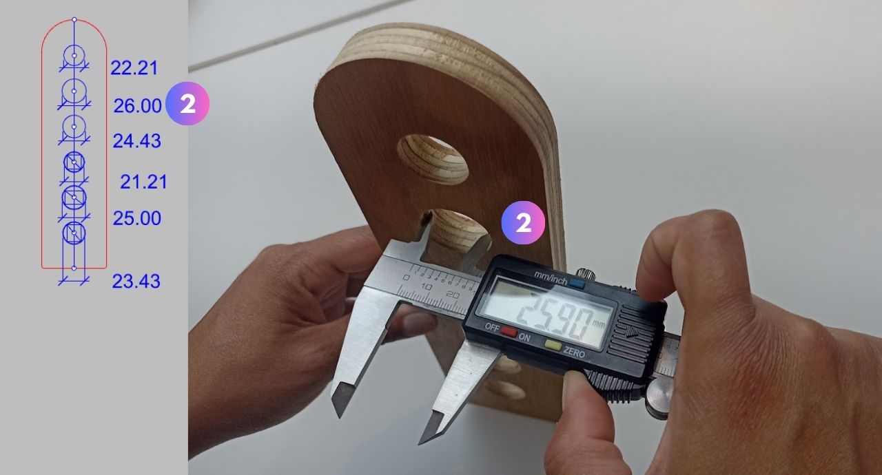
Resulting milling dimensions
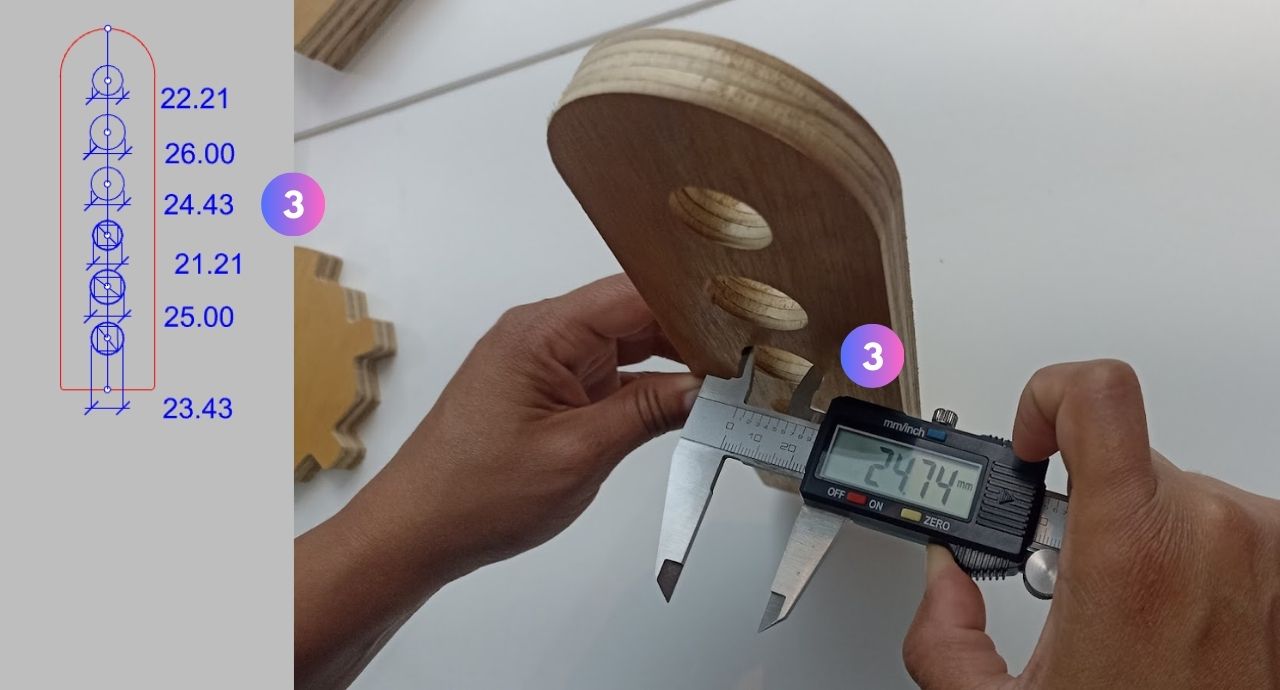
Resulting milling dimensions
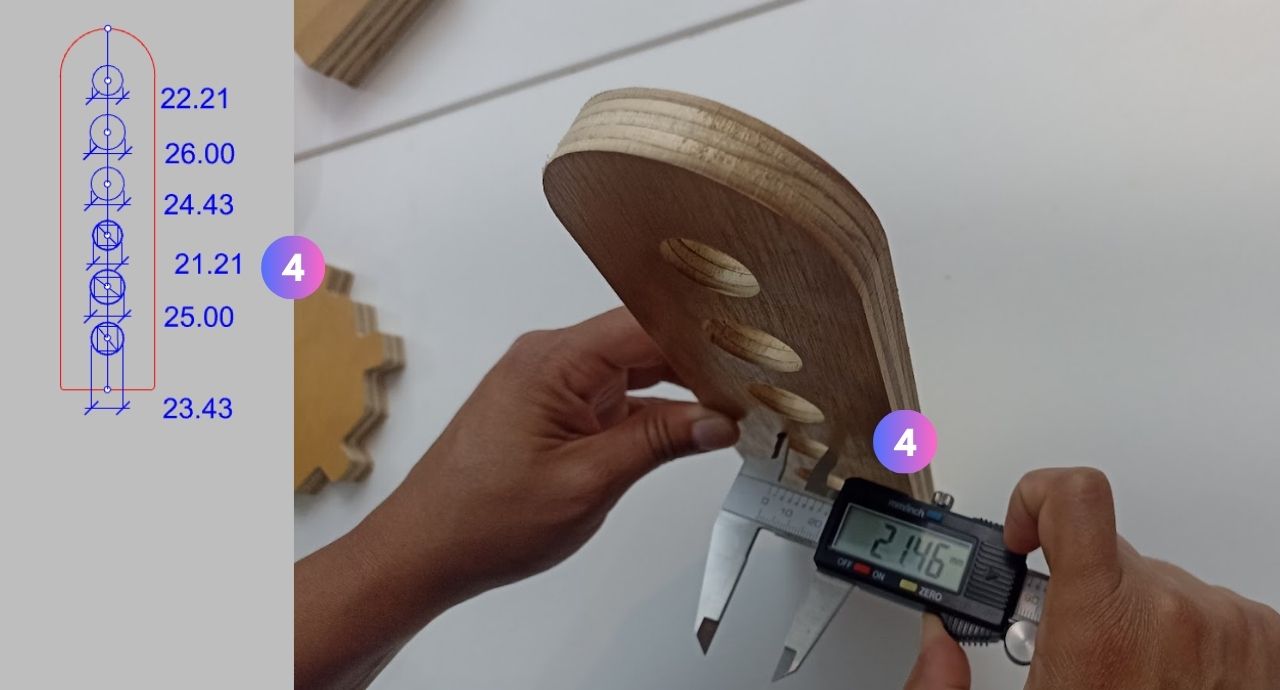
Resulting milling dimensions
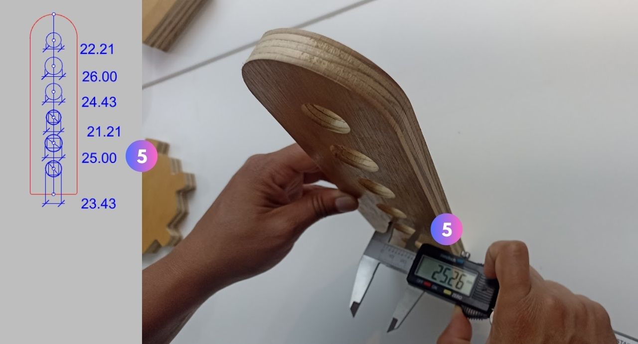
Resulting milling dimensions
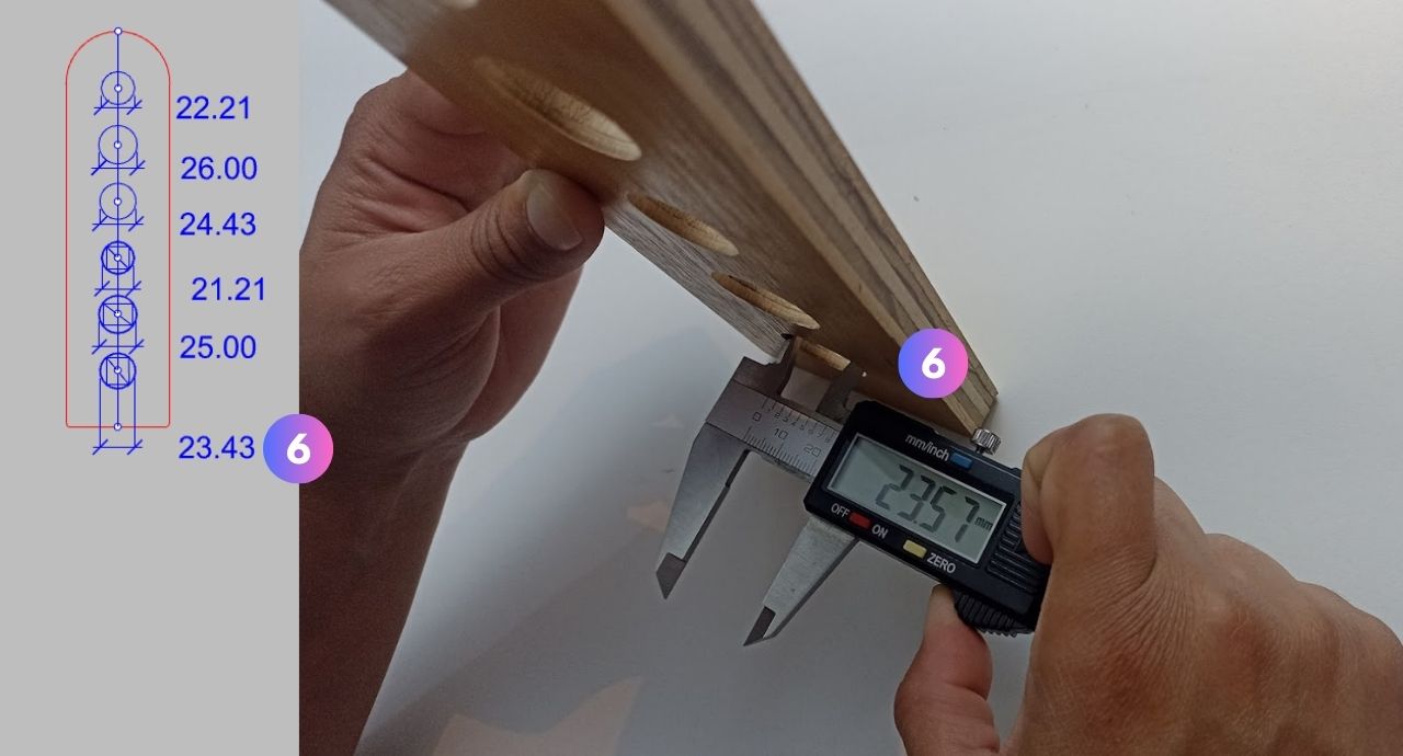
Resulting milling dimensions
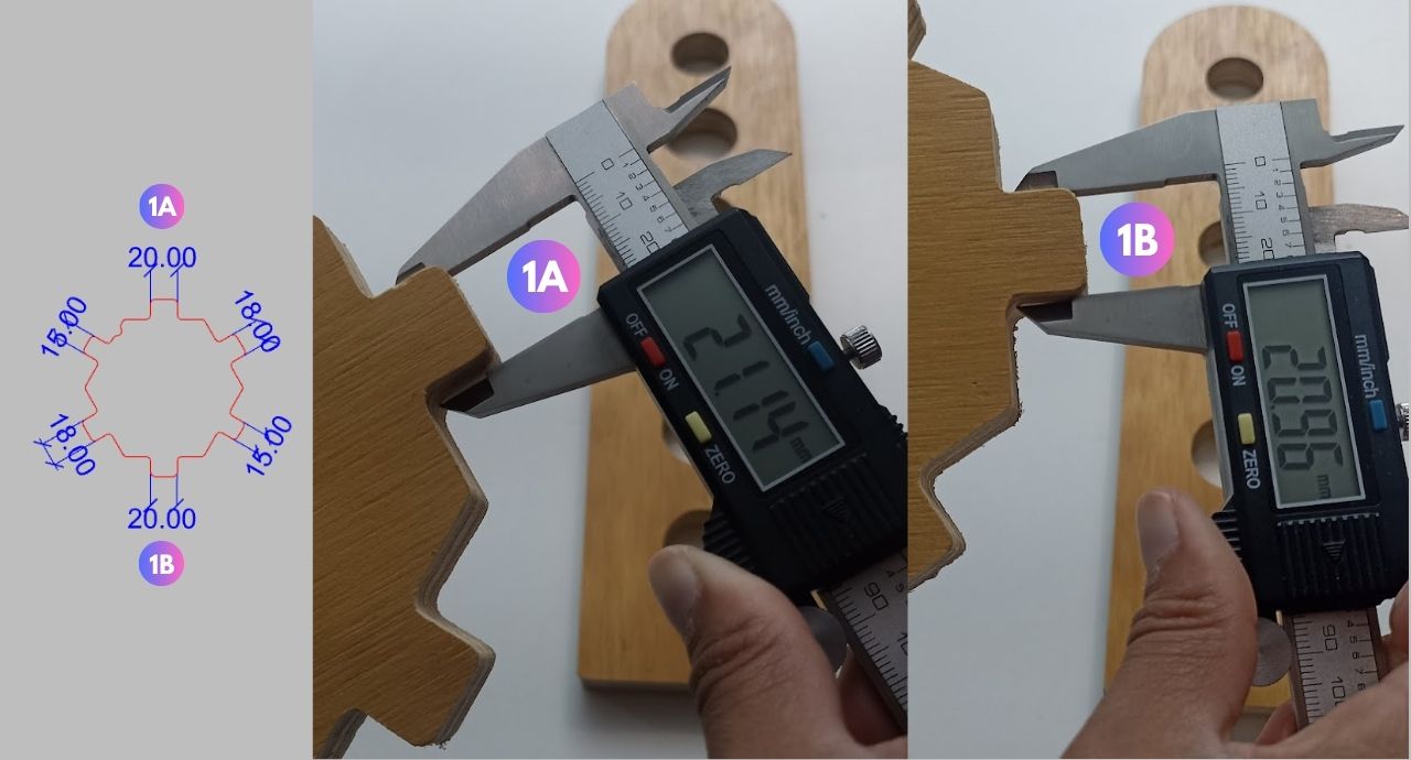
Resulting milling dimensions
Resulting milling dimensions
Resulting milling dimensions
The best option for the window hinge was size 5, where the circle had a diameter of 25.00mm and in addition we added a tolerance of 0.5mm. We used this circle size in all the pieces that received the windows. In the window frame we chose to use the 20.00 mm measurement that corresponds to the 1A-2A test. With these two sizes the window glass was smooth.
The window frames were custom-designed with recesses so as not to clash with other parts.
Window hinge rotation
Cutting window test
Artcam window and G-code cutting process
GRLB Controller
Window frame cutting

Finished window cut

Finished window cut
Lorem ipsum dolor sit amet, consectetur adipisicing elit. Ab architecto est, ducimus quo deleniti provident aspernatur perspiciatis ullam ipsa nulla voluptate suscipit voluptatibus autem, dicta ipsam recusandae id, assumenda at?
Window movement
Assembling skylight
After finishing the design we cut the model of the skylight in acrylic to scale to validate the sequence of the assembly. How is it done? you reduce the file so that all the sockets are of 3 mm. which is the thickness of the acrylic and then cut it in a laser cutter. In addition, all the pieces are labeled to identify them and make the assembly easier.
We put all the cut pieces of wood where they were to be assembled, joined the pieces that were cut separately and once everything was ready we proceeded with the final assembly in the correct sequential order without the need for bolts or screws.

Laser cut acrylic mock-up

Kit of parts

Skylight assembly

Assembling the roof

Side side of skylight

Installing the windows
Final
Finally, together with Mayra Ascencio, we were able to assemble the skylight, which is a really big element of 2.0x1.0 m. approx. where the windows work perfectly.

Front view

skylight ready
Finally assembled

Finished at last

Something really big!!!
AboutLearning
- Having a small CNC means having a big challenge when you want to design something really big but it is not impossible, you just have to be creative and section the design in many pieces to achieve it.
- If your CNC is not well calibrated you will not be able to accurately cut the design, the less vibration there is the better the cut will be and the less deviations you will have.
- CNC milling is a multi-step process: first we must design in a 2D or 3D program, then we must have the files in vectors, we must process them in a program to convert them to G-code and finally drive the CNC machine with a GRBL program and have many considerations between one process and the other to get everything right. Also you have to be considerate with the milling cutters and the effort that the machine makes, so it is advisable to round all the corners and the joints at 90°.
My Verdictfrom what I learned
- Although these CNC machines use more delicate cutters, the 6.3 mm cutters were excellent for cutting all the parts and did not present any problems. So I learned that you can work with what you have.
- For such large jobs it is important to work as a team and Mayra and I did a great job to complete this assignment.