Helmut Uwe [OOVAE] Terton - Fab Academy |
||
Helmut Uwe [OOVAE] Terton - Fab Academy |
||

Assignment tasks for Week 5:
Group assignment
Contents
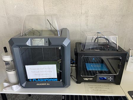
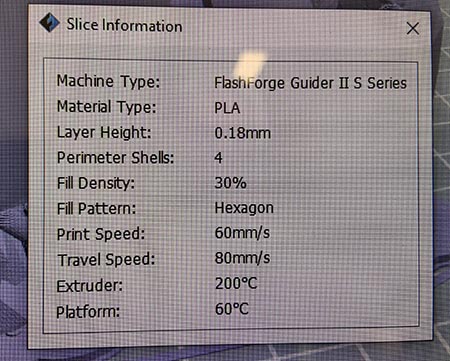
In 2022 I have used the FlashForge Guider II S Series:
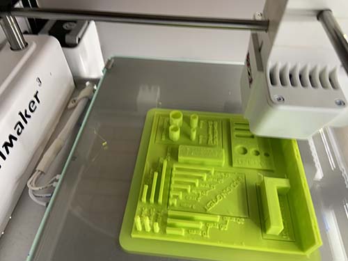
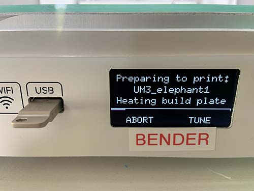
In 2023 I have used an Ultimaker 3:

I played with the size options in Cura to see how it displays the limitations of size.
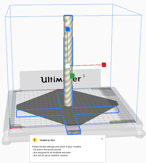
After taking it back to 178mmx178mmx200mm it was happy and I could proceed with the print.

Links to the group's assignment:
Dorian
Lisa
Summary
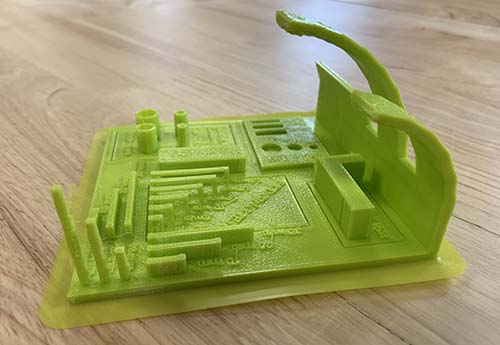
This was an excellent exercise in getting to know the slicer software Cura and the Ultimaker 3.
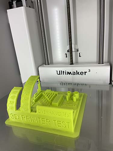
I was amazed that the Ultimaker 3 could print bridges and overhangs without any support.
This week's task was to design and 3D print an object (small, few cm3, limited by printer time)that could not be made subtractively.
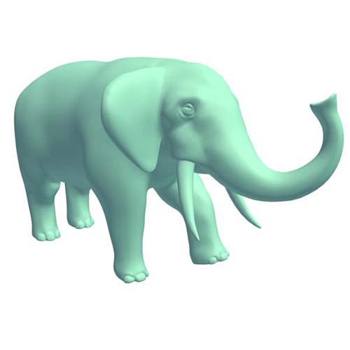
While I was thinking about an object that would be difficult to create otherwise and that an additive process would be ideal I came across an elephant sculpture from India. The sculpture has been carved out of soapstone by hand. It is a subtractive process and takes a long time.

Nevertheless object files can be exported in object (obj) files that then can be converted into a Standard Tessellation Language (STL). A STL files can be used in a Slicer software to prepare and optimise an object for 3D printing.
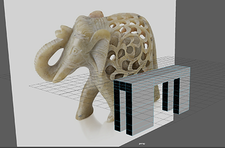
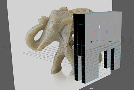
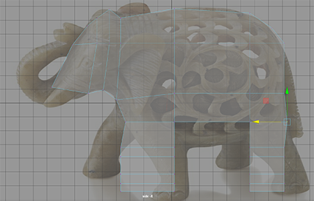
I took an reference photo and imported it into the 3d modeling software and created a polygon cube that I stretched the length of the elephant's body (figure 8).
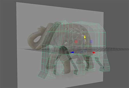

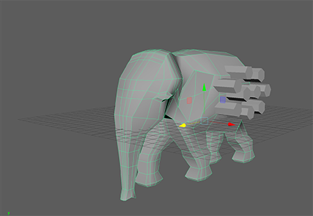
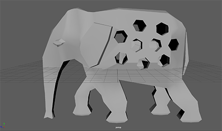
To add holes to the geometry it is best to apply a boolean/difference operation using other objects that work as templates (figure 14)

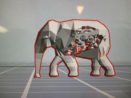
Well, this is the elephant model without holes, inner cage and baby in slicer.
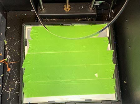
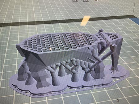
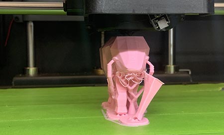
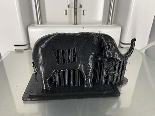
The above figure 25 shows the support that was applied to assure that the liquid print material would not sink to the printer bed.
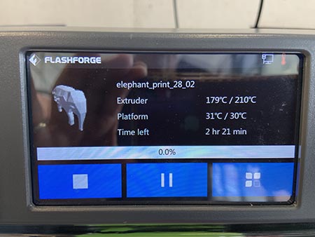
Halfway through the print I noticed that the trunk came off (figure 27), I paused the print job and tried to put it back in place but that didn't work. I continued with the print because other students were desperate to use the 3D-printer.
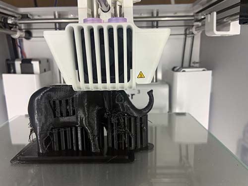
Below is the finished print, with a render spatula it was easy to scrape off the printer bed.
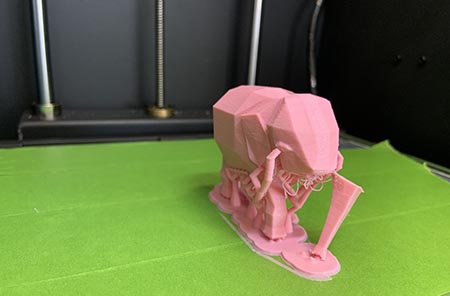
I left the support on, it looks kinda groovy.
I plan to fix the geometry and try another print. Lessons learned are that it always takes longer than anticipated. Good planning and knowledge is key and of course practice, practice, practice.
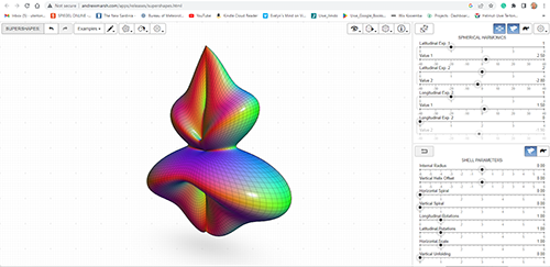
In 2023, my initial idea was to create a shape that is informed by mathematical formulas and I came across Andrew Marsh's website that let's users create interesting shapes. It turned out that the site has no export function, so, I had to find something else.
http://andrewmarsh.com/apps/releases/supershapes.html
I thought that I could continue with the Fibonacci informed shapes such as the Nautilus and started tracing a shape in Illustrator. The plan was to import the illustrator trace into Fusion 360 to continue makeing a 3D model of it. I visited the following tutorial to learn mor: Tutorial SVG illustrator to Fusion 360
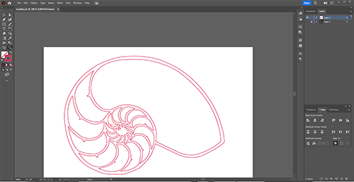
After the tutorial it became clear that the assignment is to design and 3D print an object that would be very difficult to make otherwise except through a six axis CNC router.
Last year I designed an elephant with an elephant inside and decided to continue with that idea.
Last year's printing didn't go very well, I wasn't able to print the holes because the mesh was messy and had manifolds. I only ended up with the outer shell and a broken elephant trunk.
From last year's leaning I decided to use an existing mesh from free3d https://free3d.com/3d-model/elephant-v1--382262.html
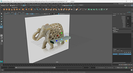
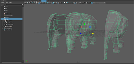
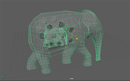
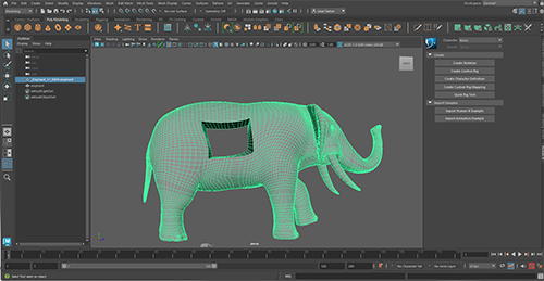
I imported the mesh in Autodesk Maya and modified it so that it could hold four elephants inside.
Maya is not suitable for making models for 3D printing because it uses only shell modelling modes and not solid.
Again, being time smart and therefore I decided to stick with the software I know best. Hopefully, one day I can learn other software tools.
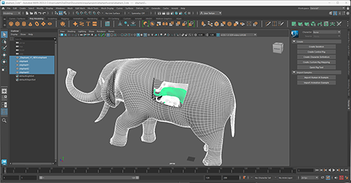
After that I made a flat base that would make it easier to 3D print the object.
Once the model was complete I exported it as an OBJ file.
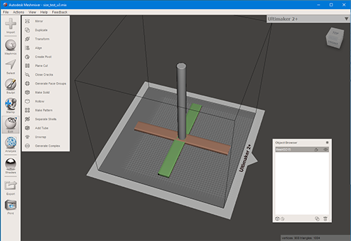
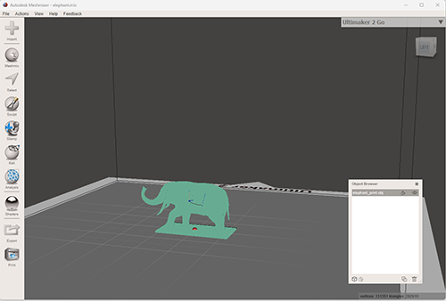
Next I opened Autodesk Meshmixer to resize the elephant to 12cm length and exported it to an STL file.
The STL can be easily opened and read by CURA, the slicing tool I was using for this project.
I saved a STL copy that could be imported into CURA.
Cura is an open source slicing application for 3D printers. It was created by David Braam who was later employed by Ultimaker, a 3D printer manufacturing company, to maintain the software.
Cura 4.3 can be downloaded from here: https://ultimaker.com/learn/ultimaker-cura-4-3-available-now
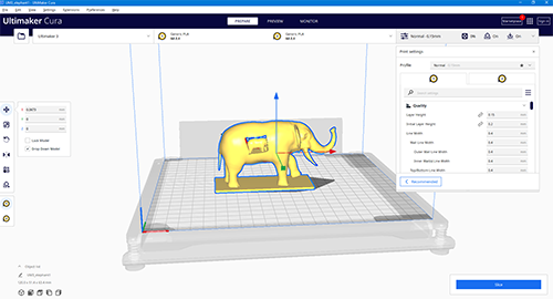
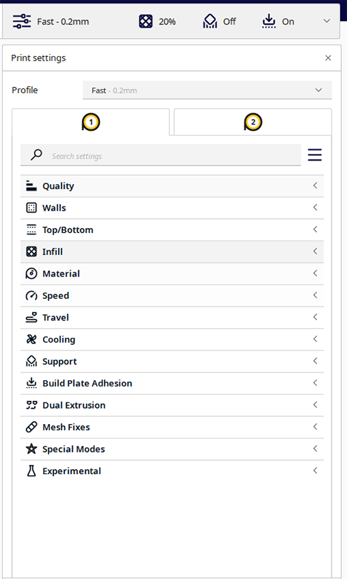
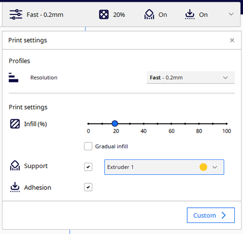
Cura offers a plethora of options to fine tune print outcomes by setting resolution, material, infill, support (scaffolding) patterns, rafts and more.
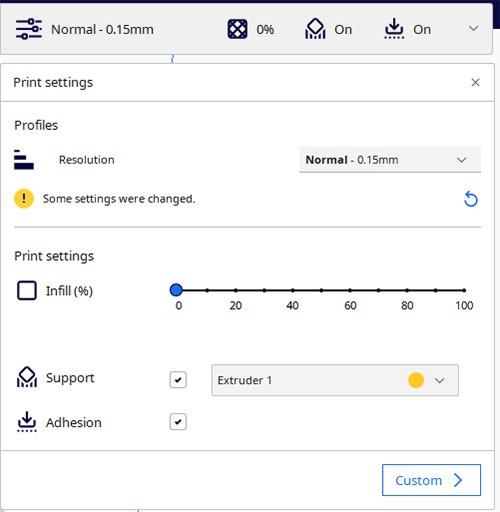
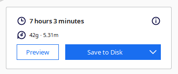
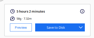
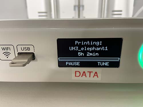
I started out with a very fine resolution 0.15 mm but it created a very long print duration of over 7 hours. By changing the resolution, I was able to reduce the duration to just about 5 hours.
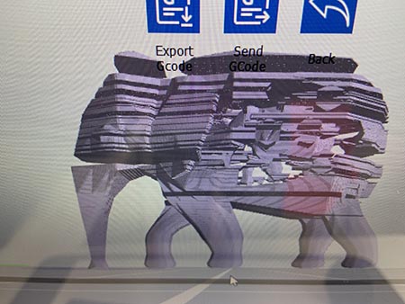
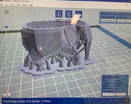
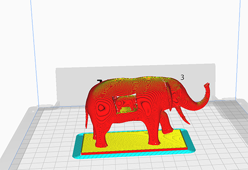
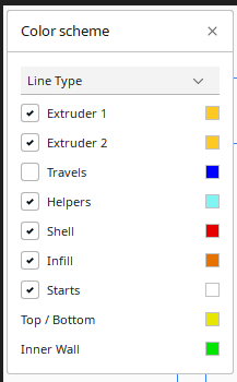
Once I was happy with the set-up I hit the slicing button and received the following preview, which indicates aspects of the print such as shell, infill, raft and support as shown below and in the colour scheme figure.
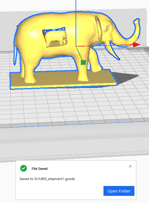
Last step was to save the file in Ultimaker's G-Code. G-code consists of G- and M-commands that have an assigned movement or action.
The G-Code is used by the printer to actually print the object.
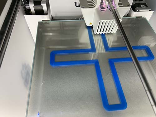
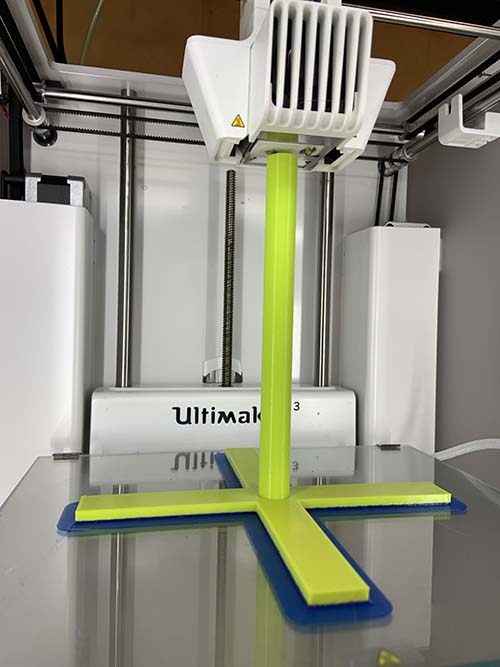
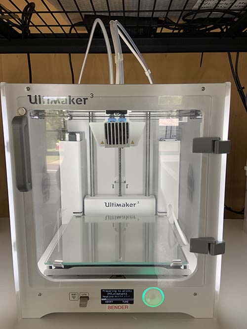
Below is an image of the Ultimaker 3 that I used for this project print.
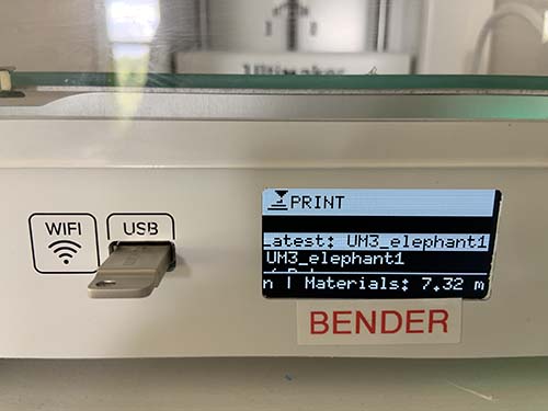
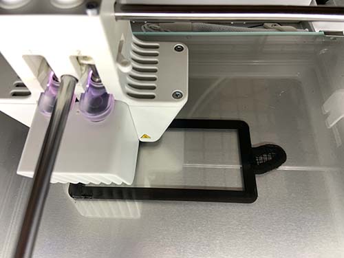
The printer laying down the raft, which is a horizontal mesh of filament deposited directly onto the build platform.
Summary:
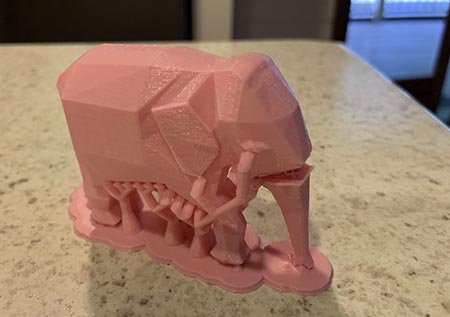
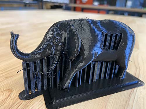
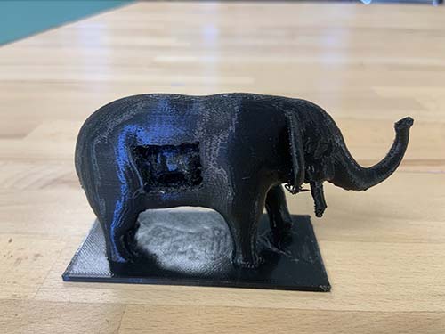
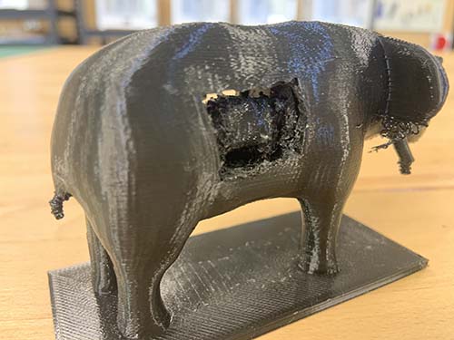
The quality of the print was clearly diminished by clipping off the support and damaging the plastic surface of the elephant. Some detail such as the tusks and tail of the elephant didn't come out as planned. 3D printing with the equipment on hand should be only used for prototyping. It is not suitable for mass production due to imperfections and time it takes to print objects. The elephant is just 12 centimetres in length and it took 5 hours to print plus one hour cleaning up support manually.
I think I should try printing the elephant model without support, just to see if it works and this would create a much more detailed print especially for the three small elephants inside the large one.
If used for prototyping and proof of concept or for visualisation purposes, it is truly an amazing technology. The revolution predicted over 20 years ago is still to come.
My lesson learned from this assignment is that I need a lot more practice with different modelling software and printing objects with different requirements and different printers to be able to help and advise in 3D design and printing. It always takes longer than anticipated. Good planning and knowledge is key and of course practice, practice, practice.
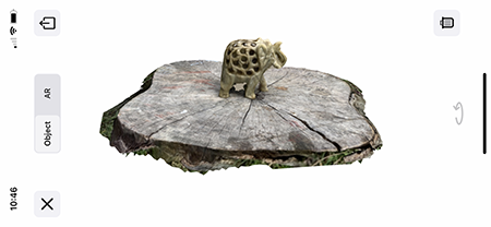
At USC is a HP PC with a Sprout 3D scanner that unfortunatly produces very bad results. I therefore tried photogrammetry via the Trnio app.
I had put my model on a timber stump outside, the sky was overcast, ideal conditions for photogrammetry.
According to Wikipedia: "Photogrammetry is the science and technology of obtaining reliable information about physical objects and the environment through the process of recording, measuring and interpreting photographic images and patterns of electromagnetic radiant imagery and other phenomena".
I took 9 photos making sure that I keep the same distance and angle to the object.
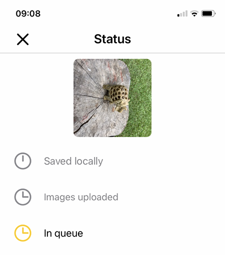
Once all images had been taken they were sent via the app to Trnio cloud render service. When the render was completed I was sent a message and could download an OBJ or STL file.
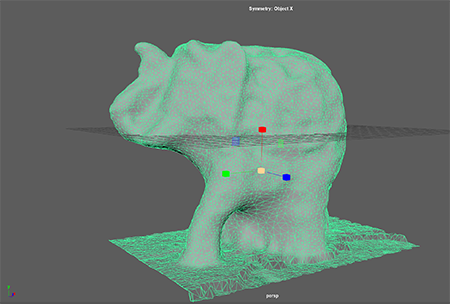
The mesh resolution is huge and very messy and not so detailed as expected. In the app preview it looks stunning because of the image map overlay. The mesh model was so bad that I decided not to print.
Lesson learned: It would be nice to have had access to some or even one high performance 3D scanner to see the difference and learn how to operate the scanner. I might try to get hold of one from a different source.