Mechanical & Machine Design
This page serves the purpose to show the work done by the students for the Mechanical & Machine Design.
Project idea
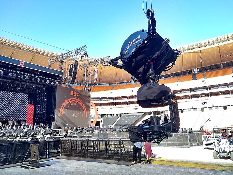
We started the Mechanical Design week project during the first pandemic lockdown, so it was restricted by our lack of lab access, as well as shortage in parts. We discussed several project ideas, looked at what we had in terms or parts and materials, and agreed on making a Spidercam, similar to football stadium hanging cameras, but scaled to a fablab/makerspace where there was the desire to remotely monitor the machines and possibly control them having the benefit of a close view.
The idea came from Marius because it would be nice to have some sort of way to check remotely the lab machines at work. He is setting up this new Arteria FabLab so this could eventually be usefull.
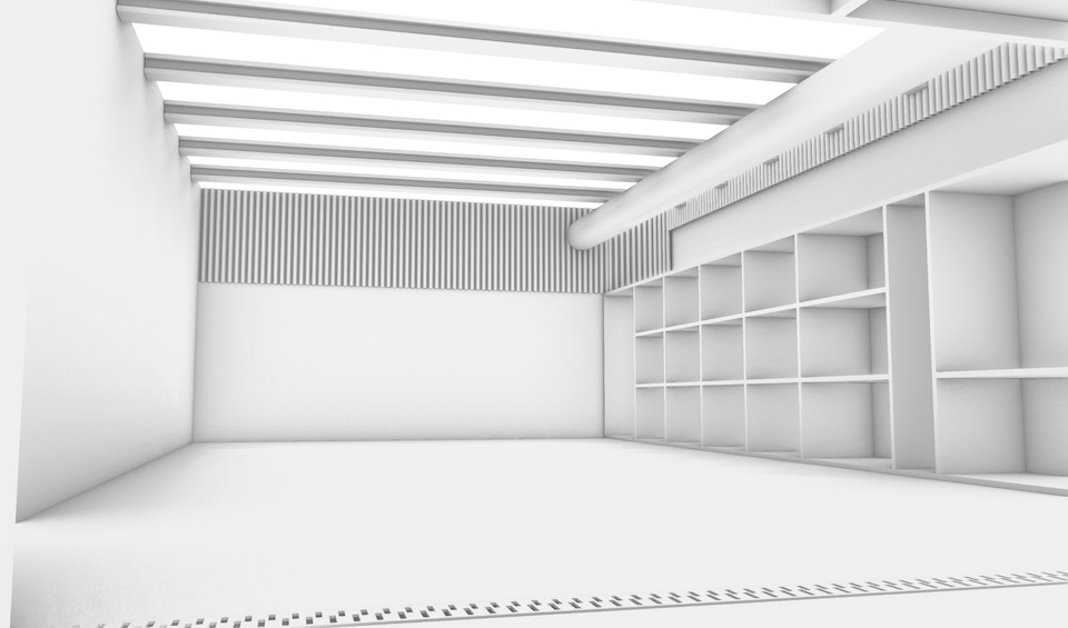
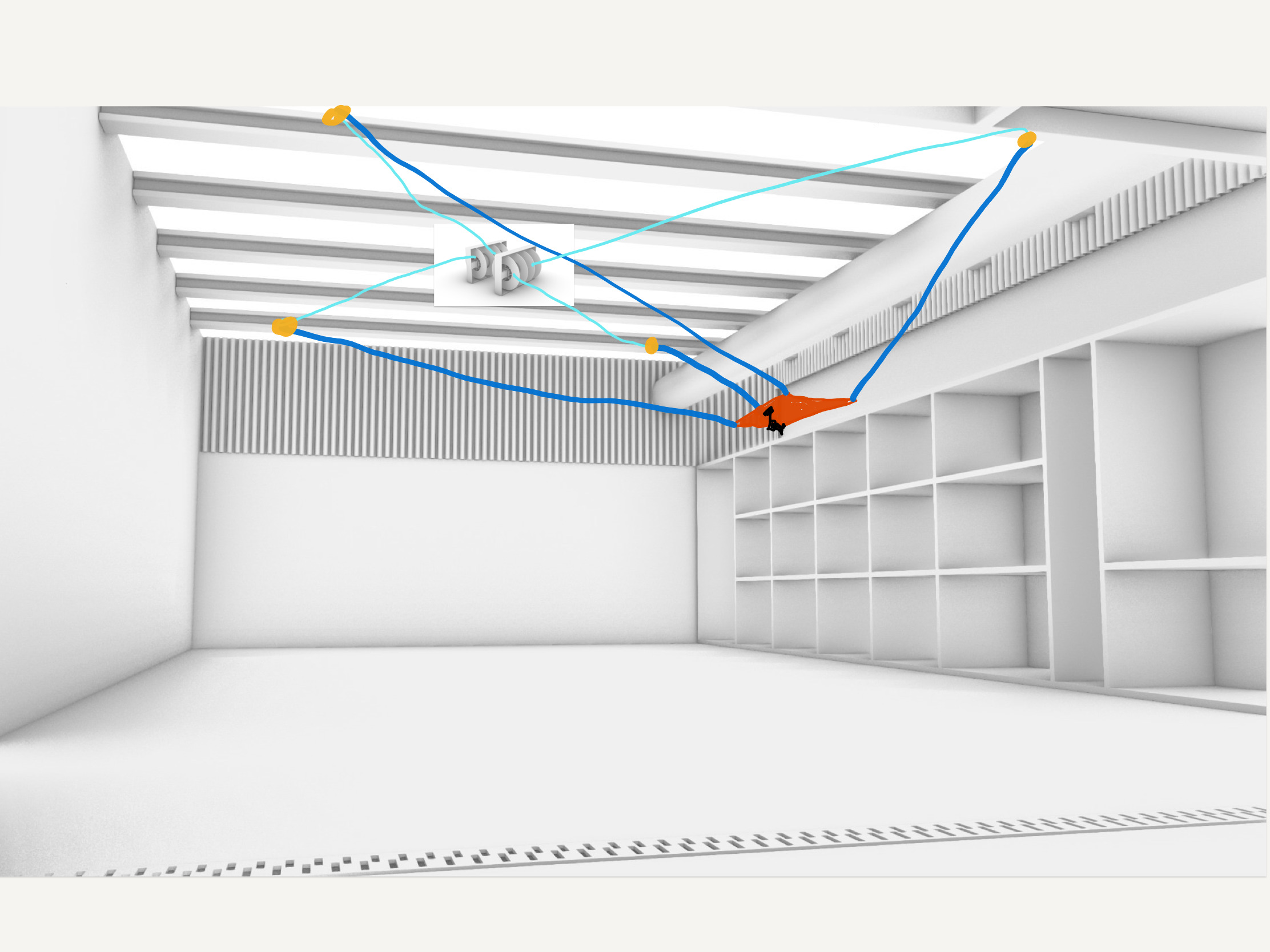
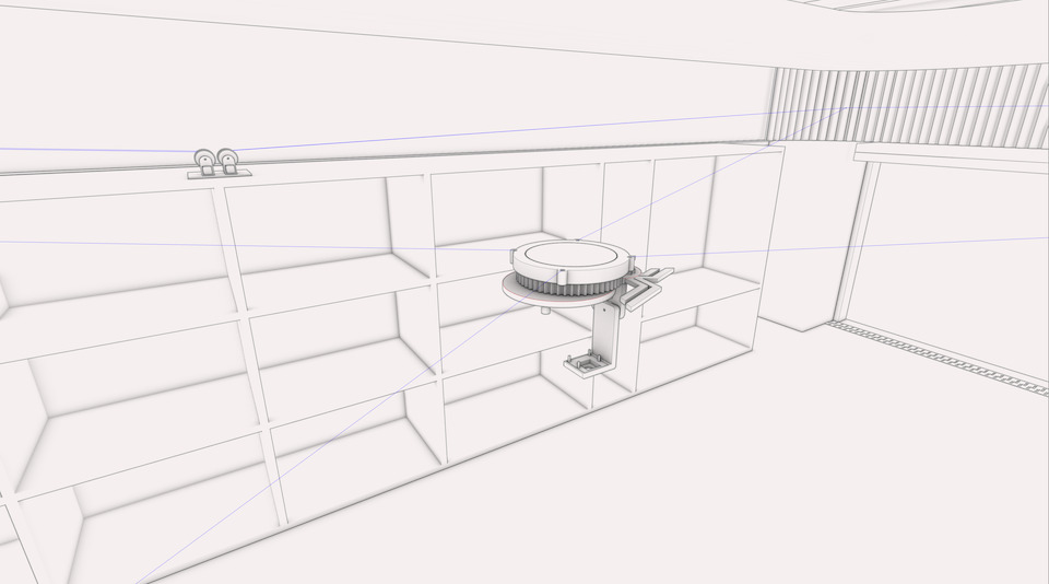
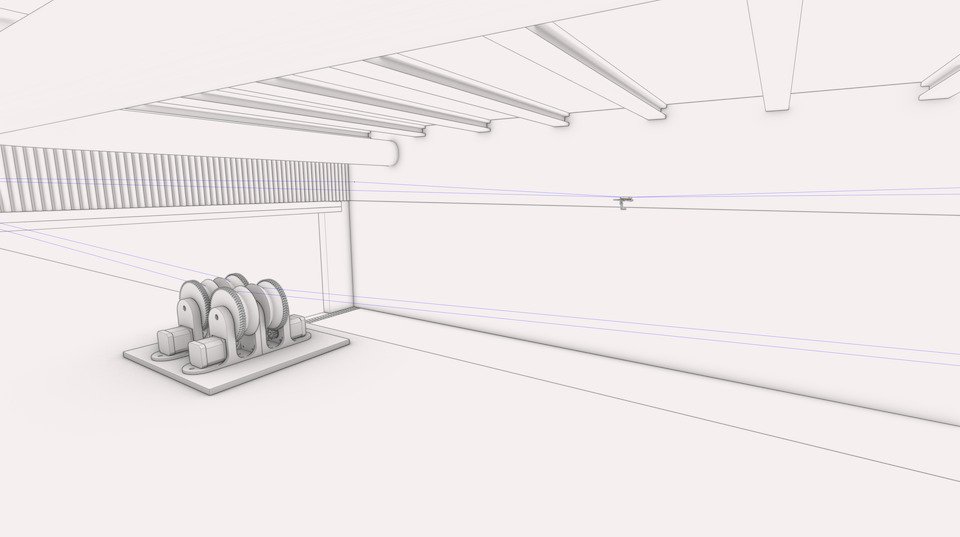
The room to test
3d representation of _Arteria_Lab
Actual _Arteria_Lab
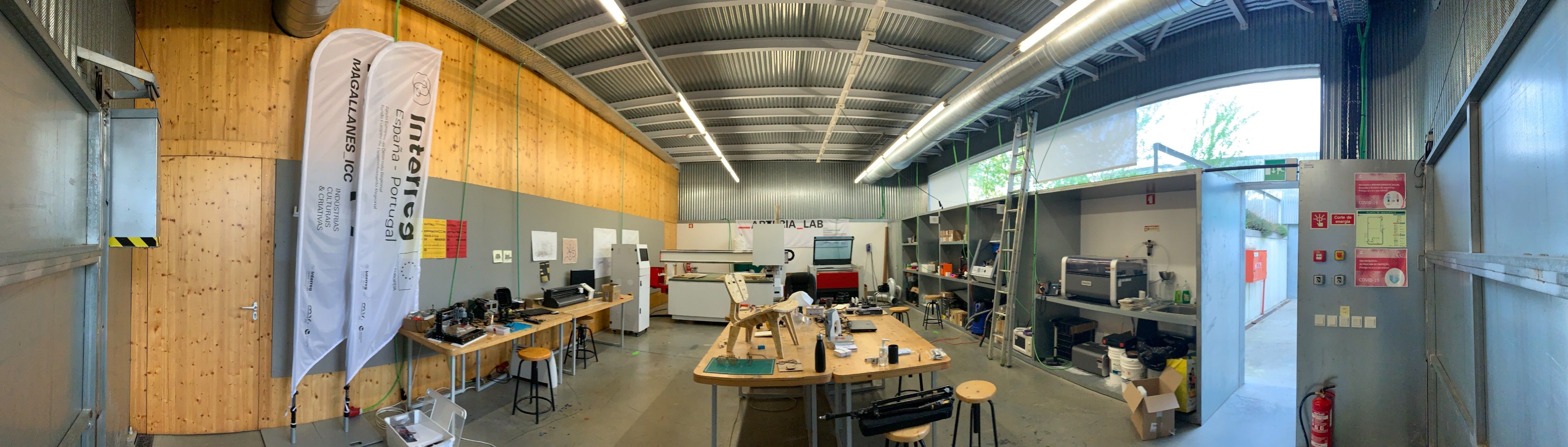
So the idea to use a spidercam looks good, it has some good height and clear space above the furniture and space.
| Mechanical Design Plan | Status |
|---|---|
| 1. Mockup how to controll 4 cables | done |
| 2. Mechanical design of motion system controll | done |
| 3. 3D printing of motion system parts | done |
| 4. Mockup of Camera Gimbal (YAW/PAN, Pitch) | done |
| 4. Mechanical Design of Gimbal with space for raspberry | done |
| 5. 3D print Camera Gimbal | done |
| 6. Operate Manually | done |
| 7. Tweaks/Improvements | done |
| 8. Document | in progress |
Mechanical Design
Individual Documentation
Group Documentation
- Shown how your team planned and executed the project
- Described problems and how the team solved them
- Listed future development opportunities for this project
- Included your design files
- Optionally included an aprox. 1 min video (1920x1080 HTML5 MP4) + slide (1920x1080 PNG)
Group Assignment
- Design a machine that includes mechanism + actuation + automation
- Build the mechanical parts and operate it manually.
- Document the group project
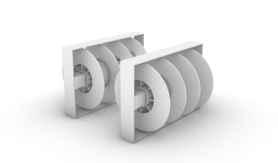
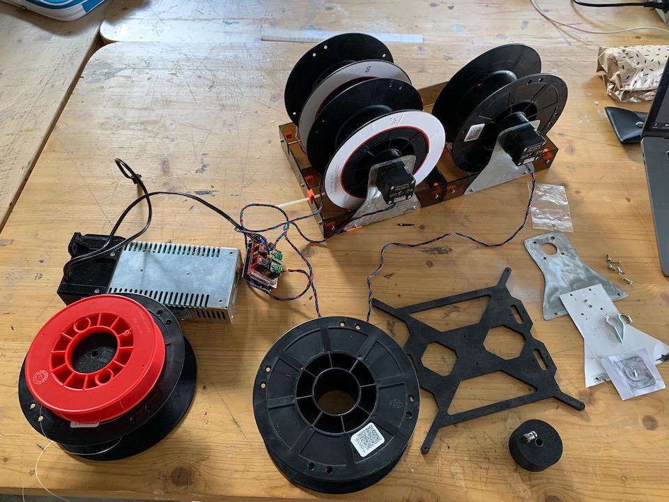
For the 1st design mockup we used 3d printer filament spools connected to stepper motors to allow to pull/release coconut rope. The rope at the other end would have a camera gimbal operated by a raspberry pi with a Pi cam. The restricton was to use “stuff” that we had around at home that could be used to design and later build this machine.
Mockup of how we could setup the spidercam. This inicial mockup served us to try to visualise how it would work, where cables would need to be passed and tied to the gimbal.
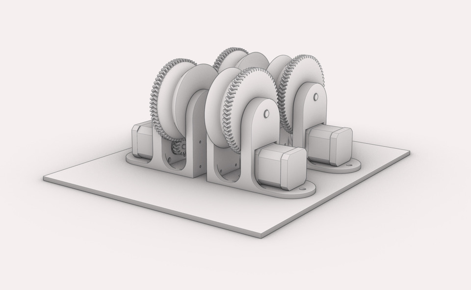
We started to build the spools for the rope mechanical part of the motion system. This already included the stepper motors to later move the spidercam. This was the 1st design.
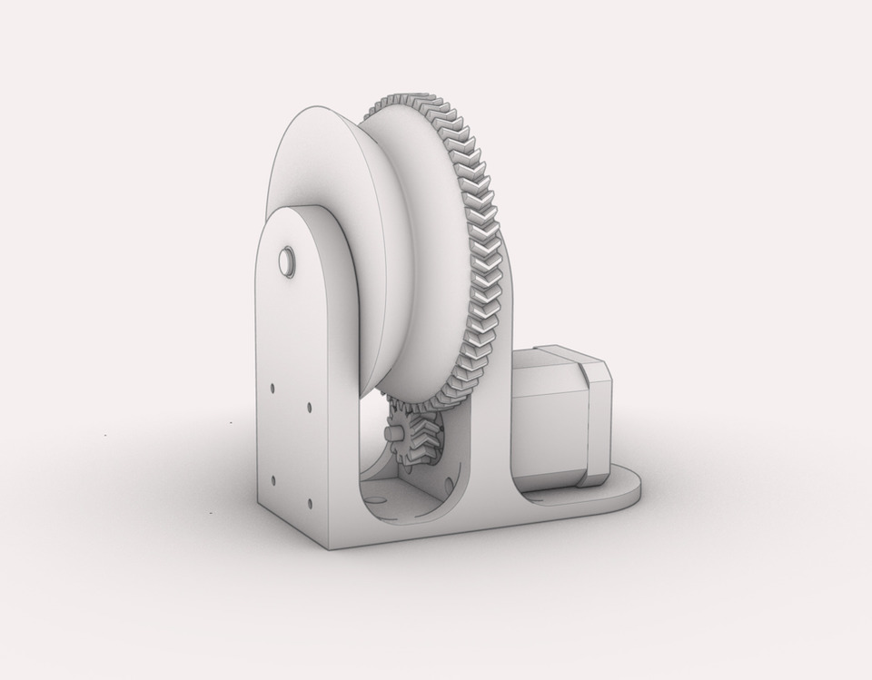
Marius designed the motion system, connecting each of the 4 steppers to spools via herringbone gears. The spools pull a thin but strong fishing wire, which is connected to the hanging base where the gimbal is located. We initially used hook screws at the corners of the makerspace.
You can see it being manually operated.
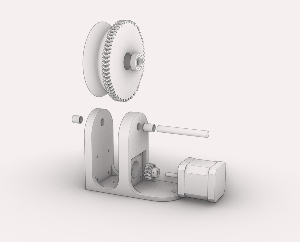
Than later Marius redesigned the motion system in 3D and swapped those for pulleys, for reduced friction.
The mechanical design of the motion system can be checked here on individual assignment: Weeks 17&18 - Machine Building
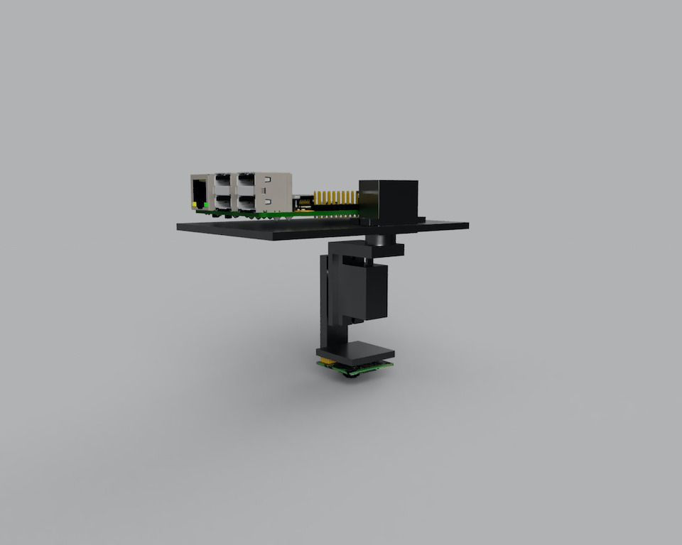
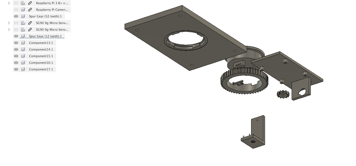
Tiago parametrically designed a gimbal system that houses the Raspberry Pi and uses the servos to rotate the assembly and point the camera, using gears and press fit to lock the gimbal. All parts were shared with Marius on Fusion 360 and 3d printed.
For the camera gimbal, the plan was to allow camera do move left/right (YAW/PAN) and up/down (Pitch) by using 2 servos. So we design a simple gimbal to be used.
The 1st design/mockups of the gimbal:
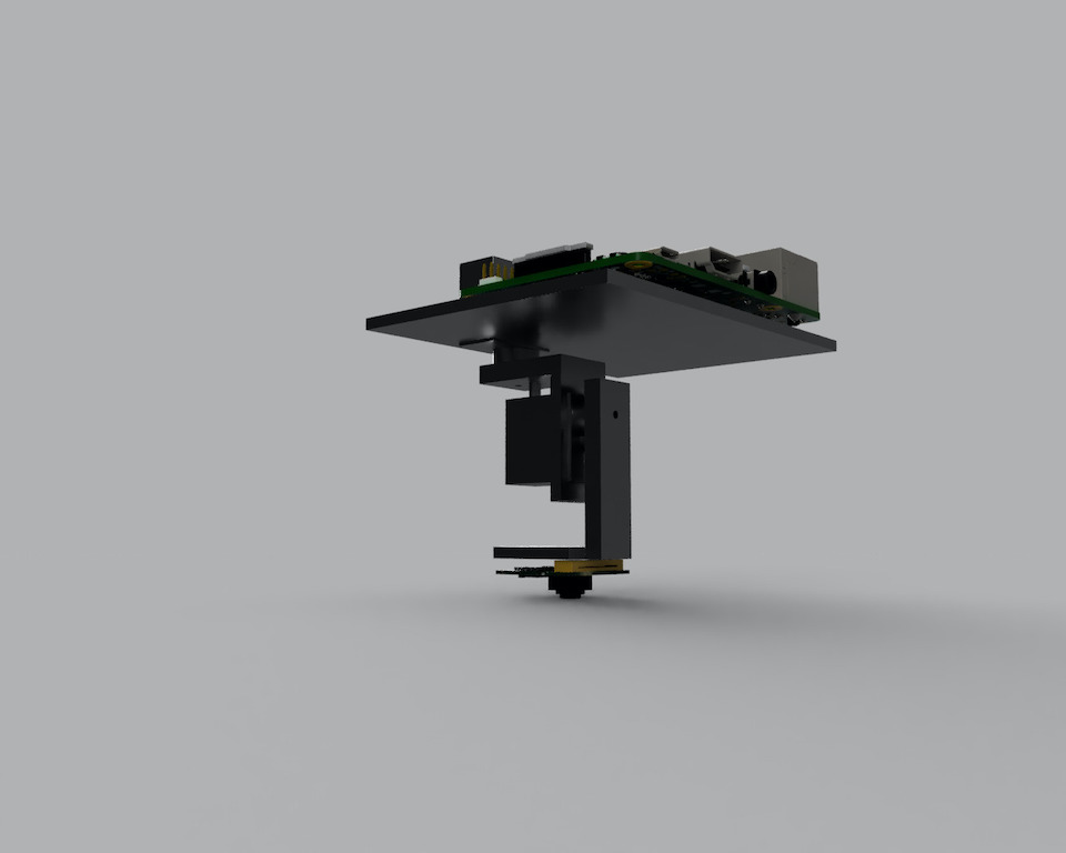
After first tests some improvements were made for moving the Raspberry Pi Camera without issues on Tilt/Pitch movement because of the flat cable.
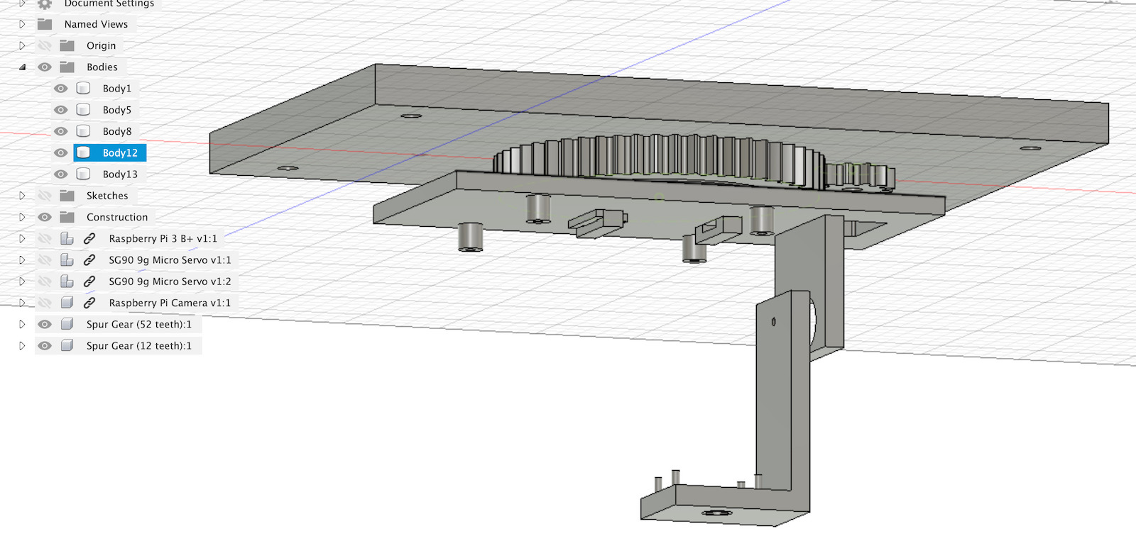
Exploded view
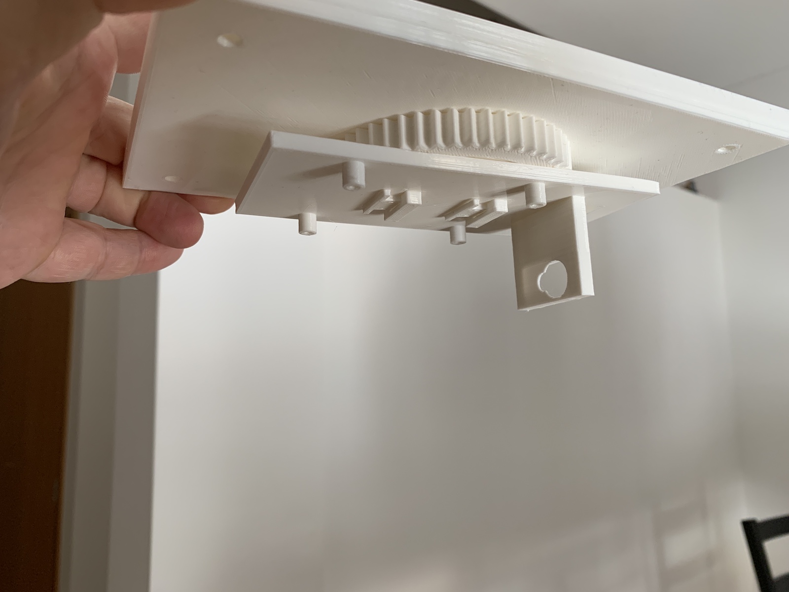
3D printed
The mechanical design of the gimbal can be checked here on Tiago individual assignment: 15. Mechanical design
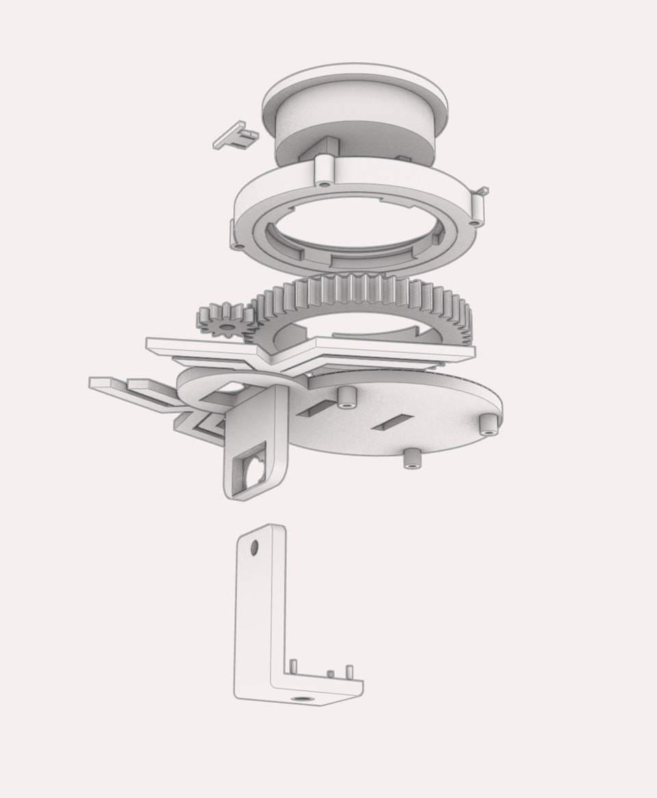
From this last design, Marius did some design magic on the gimbal for a better style :)
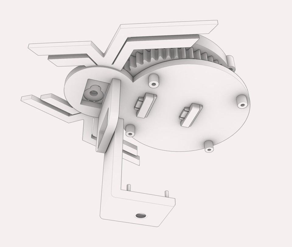
Exploded view
The last version of the spider cam design mockup, looking good!
View from the gimbal perspective
View from the other side, near the motion controller gears
For improvements, think we could design a place where the gimbal could go before shutting down (Home spot/place), or some sort of brake in the gears in case weight provides more force than the stepper motors with the gears (prevent gimbal to fly down :). Other improvements could be to design a holder for other type of camera (just the bottom part of the gimbal) or have a place to mount distance sensors (measure distance down, vertically and 4 ways in the horizontal).
Machine Design
Individual Documentation
Group Documentation
- Shown how your team planned and executed the project
- Described problems and how the team solved them
- Listed future development opportunities for this project
- Included your design files
- Optionally included an aprox. 1 min video (1920x1080 HTML5 MP4) + slide (1920x1080 PNG)
Group Assignment
- Actuate and automate your machine.
- Document the group project
For the Machine Design week we proceed to automate the SpiderCam.
Bill/List of Material gathered in lockdown/pandemic times:
| Quantity | Description |
|---|---|
| 4 | Stepper motors (42BYGHW811 Nema 17) |
| 1 | Arduino Uno |
| 1 | Arduino CNC shield |
| 4 | Stepper motor drivers Allegro A4988 |
| 1 | ESP8266 |
| 1 | Raspberry Pi Model B+ |
| 1 | Raspberry Pi Camera |
| 1 | Tower Pro micro servo SG90 (360º) for rotation for YAW/PAN |
| 1 | Tower Pro micro servo SG90 (180º) for Pitch |
| 20m | cable |
| 4 | pulleys |
| Machine Design Plan | Status |
|---|---|
| 1. Work on Arduino stepper control setup | done |
| 2. Work on ESP8266 wifi to serial communication setup | done |
| 3. Work on raspberry gimbal control | done |
| 4. Test run all connections | done |
| 5. Operate SpiderCam via web interface | done |
| 6. Make improvements/Fine tuning | done |
| 7. Make video | done |
| 8. Make slide | in progress |
| 9. Document | in progress |
We started by connecting the steppers to the CNC shield and then to the Arduino. When connected to the Arduino via serial connection we can control each stepper individually. This allowed us to do a first movement test and adjust the code so that the spidercam moved in the correct directions.
Initially we were considering to have the Raspberry Pi in the gimbal connected to the Arduino via an ethernet cable, because it has 4 twisted cable pairs, through wich we send power to the raspberry and also the RX/TX for the arduino, to send commands to. But later we decided to simplify the design and have a battery pack on the gimbal to power the raspberry and the connection to the Arduino as going to be done via local Wifi network via an ESP8266 connected to the Arduino RX/TX.
The commands sent from Raspberry requests like GET “/move/l”, which are sent via the web interface/GUI which Tiago designed to both view the image from the Raspberry Pi Camera, control the servos that pan and rotate the camera, as well as actuate the steppers to move the gimbal around the space. Then for a GET “/move/l” this command is sent to ESP8266 that in turn sends the char ‘l’ to Arduino to move steppers connected to the CNC Shield (Browser <-> http <-> Raspberry <-> http <-> ESP8266 <-> serial <-> Arduino).
So we managed to get the spidercam moving but had some issues with stepper motors and drivers used initially. We discovered that some stepper drivers weren’t good, some of the initial stepper motors weren’t also good for the task (not strong enough) so we keep improving and testing the hardware while making also improvements on the code to better control the movement of the spidercam so that it get to work more linear and less bouncy.
Stepper drivers
For the stepper drivers we adjusted the voltage to 0.96v, accordingly to the A4988 datasheet and 42BYGHW811 datasheet and formula: VREF = STEPPER_I_MAX * 8 * DRIVER_SENSING_RESISTOR
vref = 1.2 * 8 * 0.1 = 0.96v
1.2A is below what driver (2.0A) and stepper motor (2.4A) I maximum values.
In the end we manage to have a working prototype that we can connect from anywhere in the internet to move around the Arteria Lab space and see what’s going on :)
Some improvements for the future:
- Add distance sensors on all directions to prevent spidercam to hit stuff.
- Add Inertial Measurement Unit (IMU sensor) to keep spidercam always leveled on small or long movements
- Build a Joystick to control spidercam from within the lab
Video showing the spidercam moving around. Marius was filming the camera while i was remotely operating it :D