8. Computer controlled machining
The Assignment for this week was to Make (design+mill+assemble) something big.
Introduction
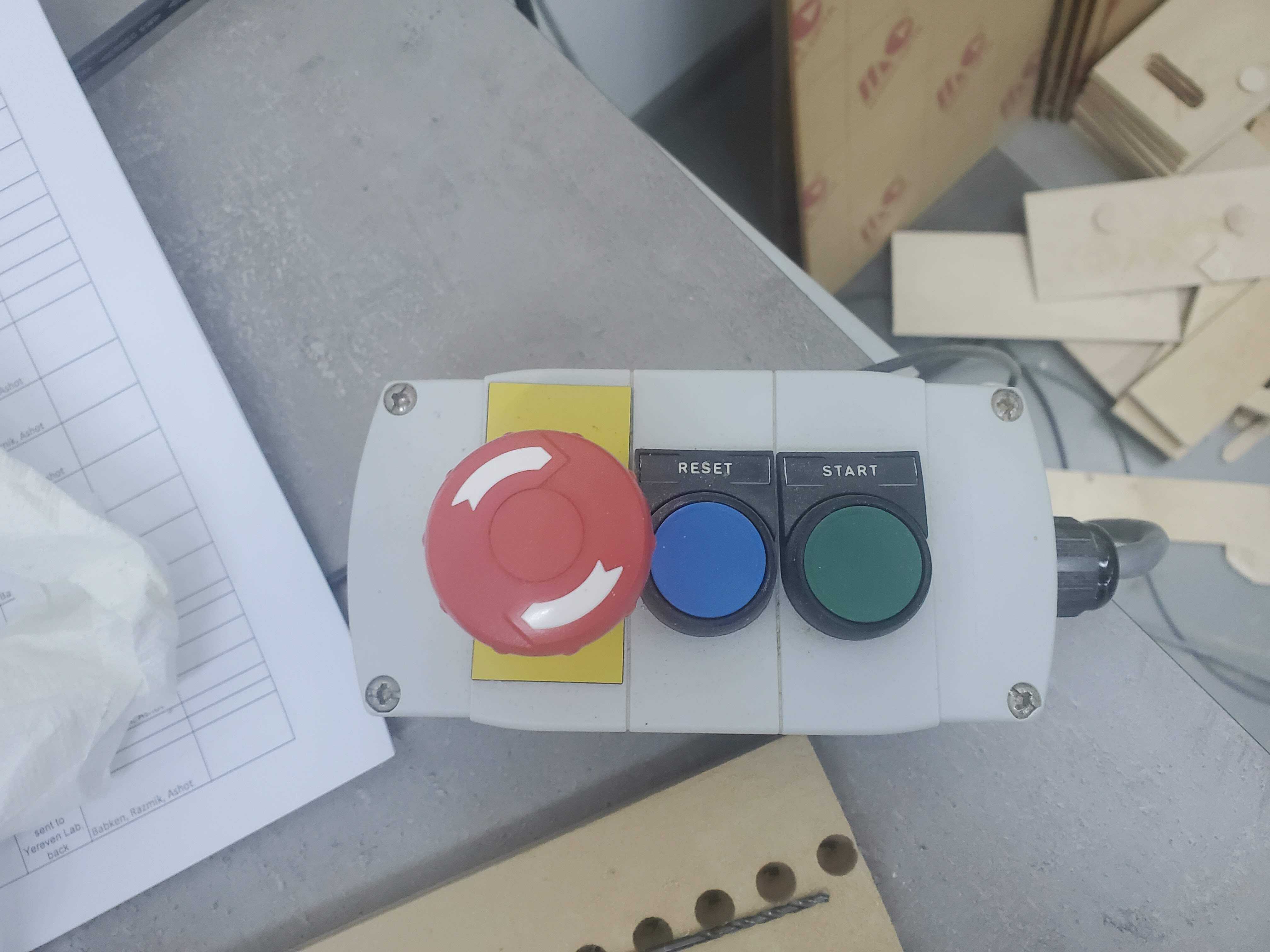
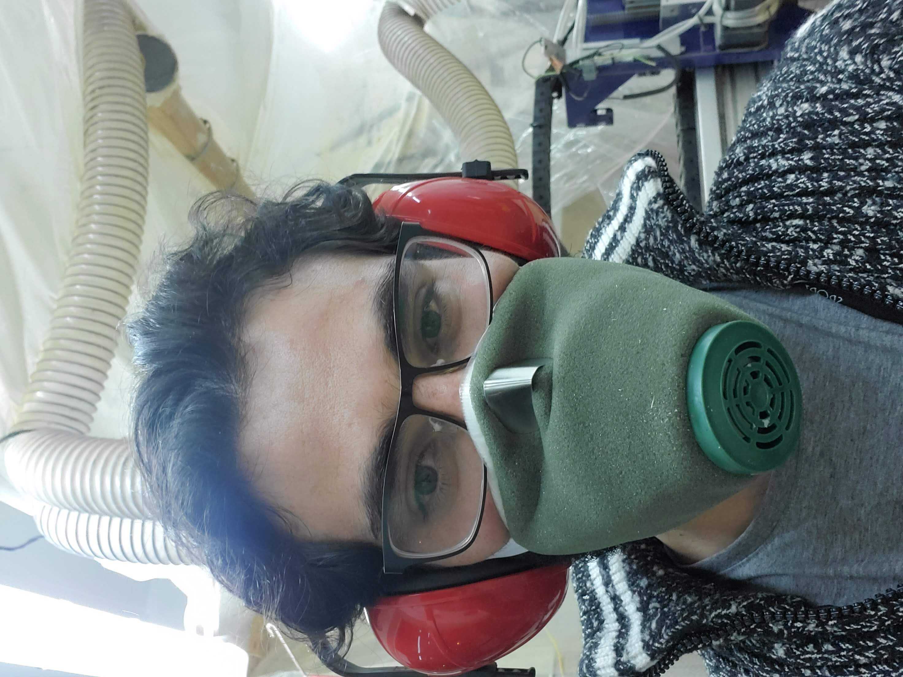
The definition of the something big is the object that is meter scale. I did a bit research to find out what to design. It was a very enjoyable and productive week for me, because I created something that was usefully, and it worked on the single try. I used Fusion 360 web at first but than having some troubles with that (session ending and not saving the work, slow and absence of dog-bones) I changed to local Fusion 360. I have learned, how does the ShopBot CNC machine works, what safety precautions it has, and how to export files for them.
Research what to make
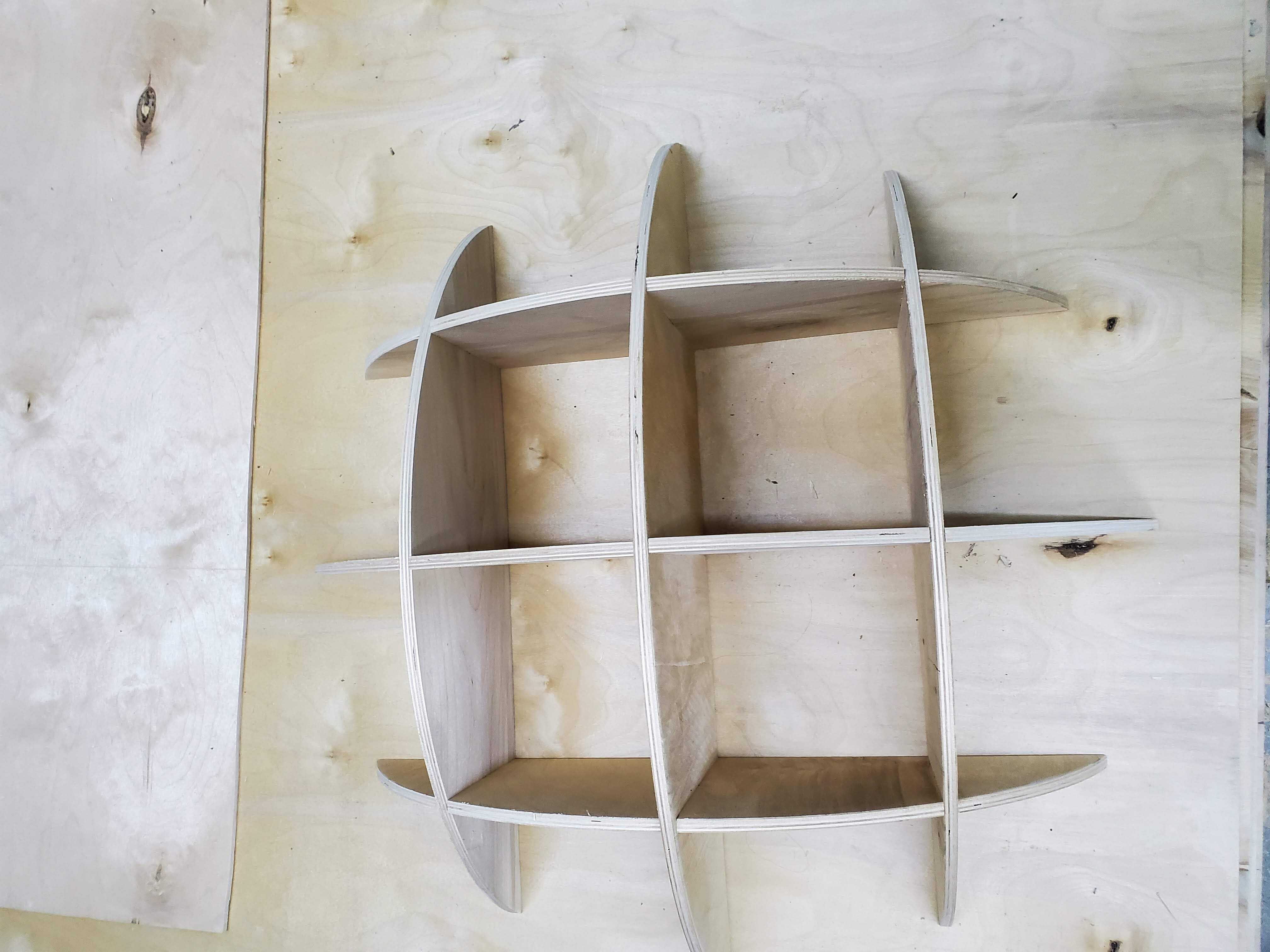
There are many options to do, but for the scope of the assignment I choose something that is neither so beg not a small, and is very useful and beautiful. I found this and many other worthwhile ideas in Pinterest. You can search for wooden arts or like me search for wooden round book shelf and you will find something like this. So as we had a restriction to design something that can be designed from one sheet of wood(1520×1220). The 5-6 cases would not be fitted on that sheet, which meant that I had to design the number of parallel cases parametric. So I started the design.
Design
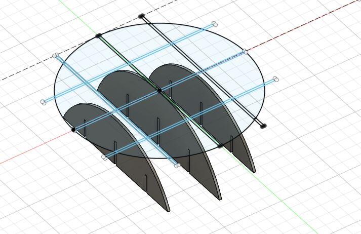
As the case is round I created construction circle and did the scotches on that circle. Here is the sketch.
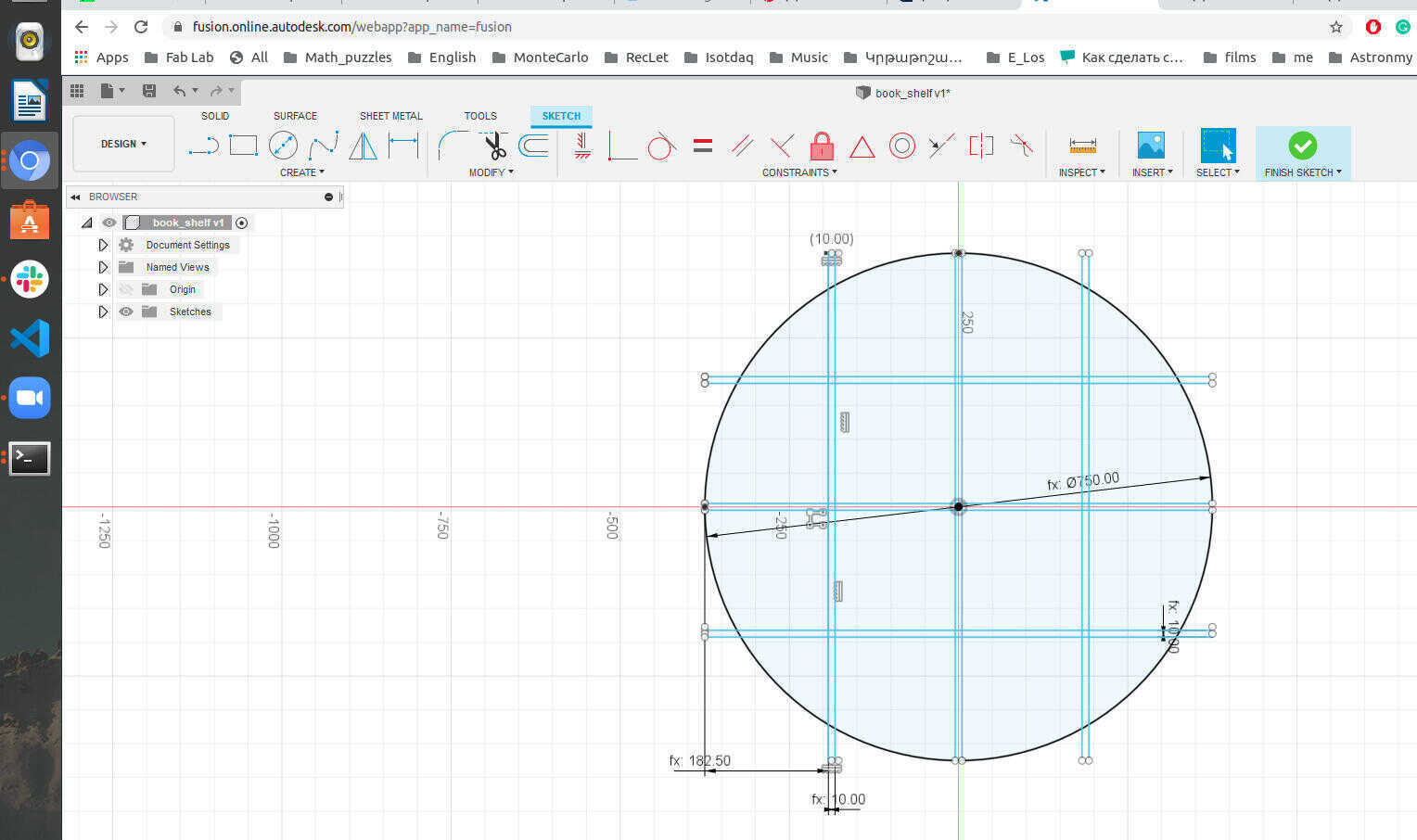
To make the design parametric I defined the diameter of the circle, and divide that to the number of the shelf plus one because the divided sections are one more than the number of lines. Here are the parameters. 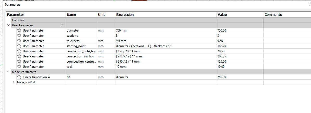
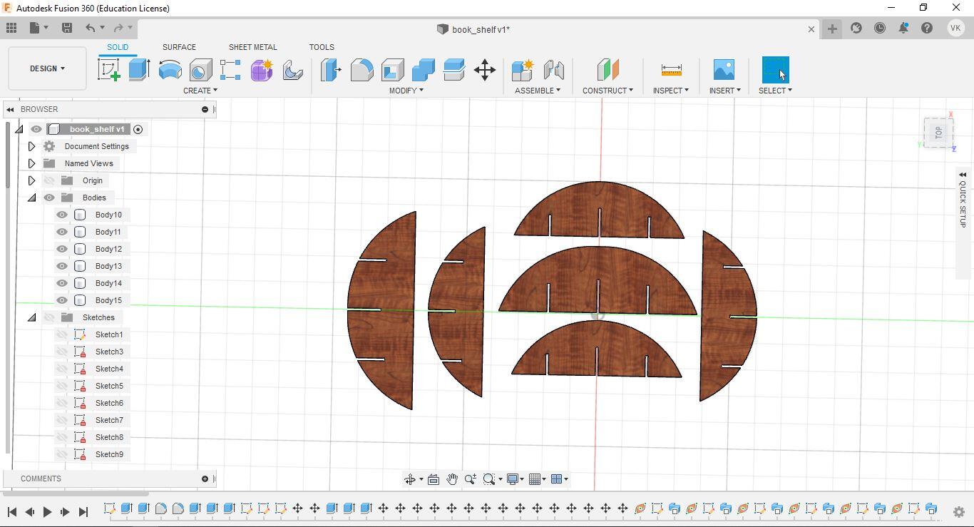
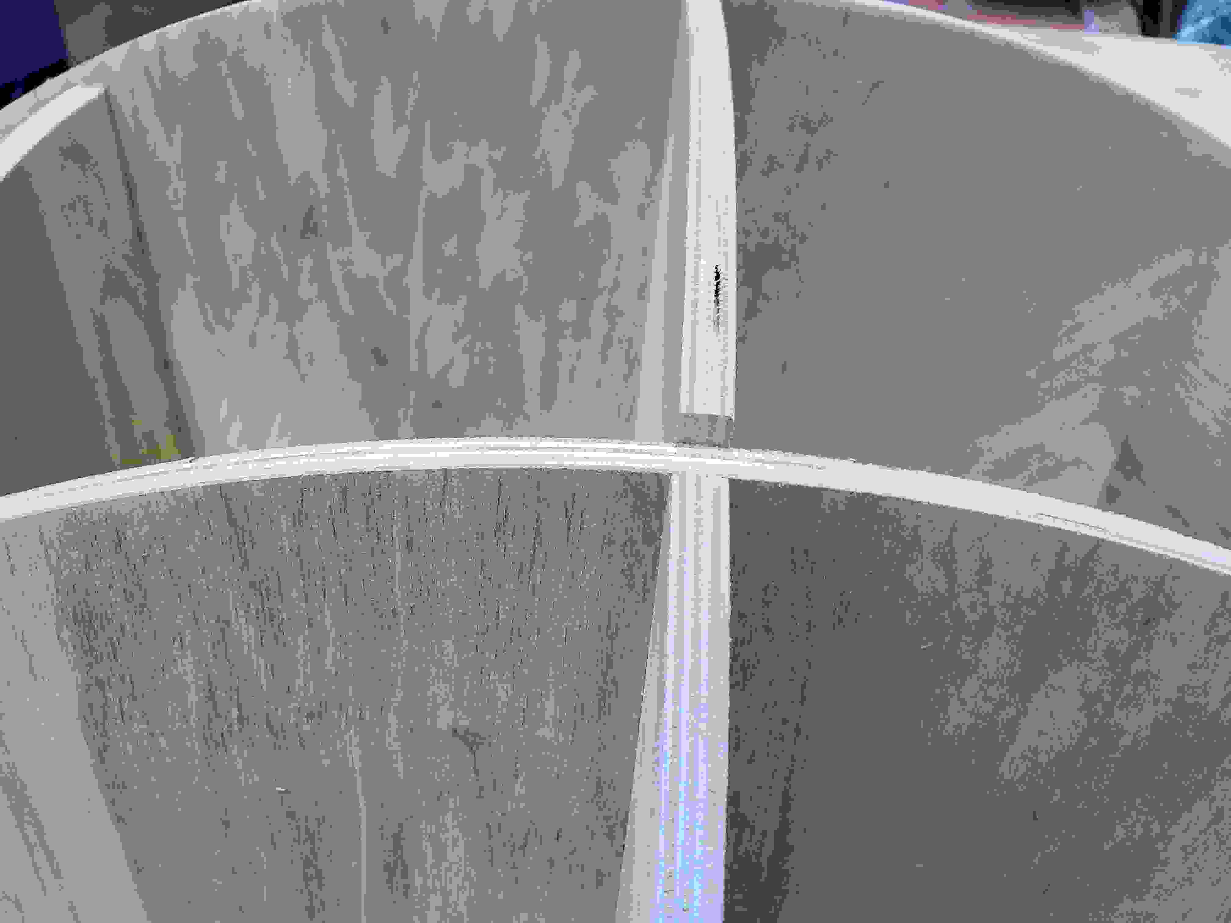
After creating the sketch I extruded the objects that are inside the circle, so in that case I had only the inner volumes. But for that to not have problems with cutting for later, I added also small connections of my lines near to the circle, because when I did not du that I have not straight cuttings, so it would be impossible for the machine to cut in 2D. After extruding I used fillet to create spheres instead of rectangles. But for this part I did spend much time to figure out how to calculate the right diameters for the fillet so I did manually.
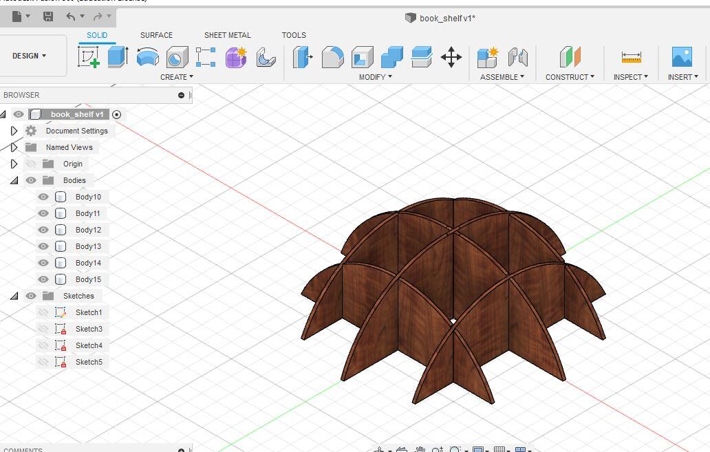
 Here you already can see the connection lines already. TO create this lines I extruded the junction squares from the sketch giving them the half length of the semi-spheres. For the upper lines to be done, I shifted the sketch a bit and extruded again from the sketch.
here is the final design.
Here you already can see the connection lines already. TO create this lines I extruded the junction squares from the sketch giving them the half length of the semi-spheres. For the upper lines to be done, I shifted the sketch a bit and extruded again from the sketch.
here is the final design.
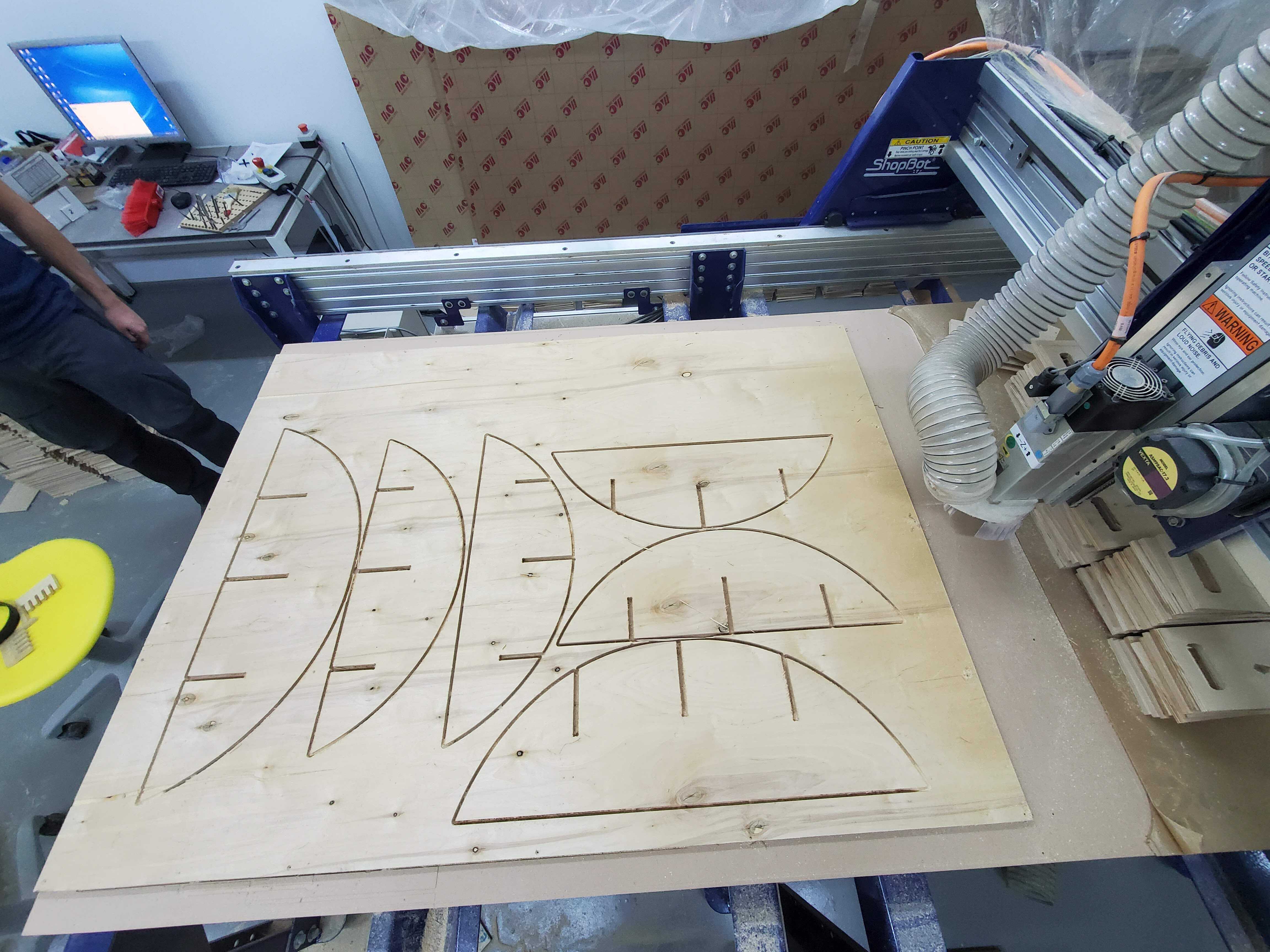
To prepare this for the machine I need to lie the parts to the ground by selecting the move and rotate by the axis in the floor axis. The nesting of the parts is very important to save material.