3. Computer-Aided Design
This week I worked on:
- Exploring SolidWorks
- Exploring SolidWorks XDesign
- Exploring Autodesk Fusion 360
- Miscellaneous Thoughs On CAD softwares
- Exploring Adobe Illustrator
- Modeling My Final Project
Exploring SolidWorks
This week began with exploring SolidWorks. SolidWorks is a solid modeling computer-aided design and computer-aided engineering computer program published by Dassault Systèmes. You can read more about SolidWorks here: SolidWorks. SolidWorks is a window-based application which means that it is only for windows. I needed to install SolidWorks on my Window computer which tool some time to do. To install SolidWork, I requested a product key from Fablab and downloaded it from the website: SolidWork In the case you are unable to retreive a product key, do a product trial.
Once I installed SolidWorks, the application opened to the home page:
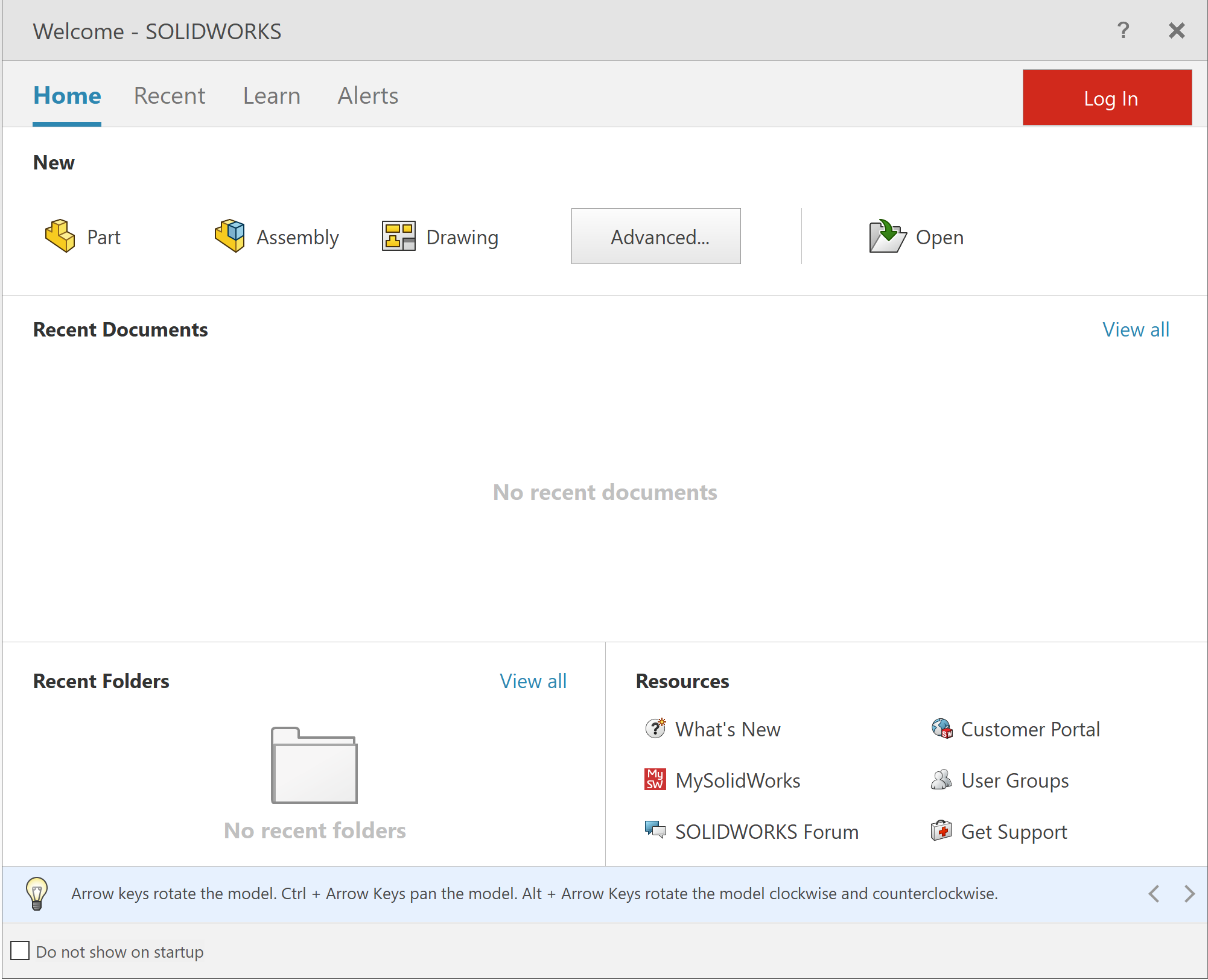
I started playing with SolidWorks to get some familiarity with it. Additionally, I used a tutorial I found on LinkedIn Learning to help with the learning process. Using a LinkedIn Learning course called “Learning SolidWork” by Gabriel Corbett made it easier to learn SolidWorks.The course is estimated to be 2 hours and 29 minutes long. The course taught the basics of SolidWorks. It was a SolidWorks crashcourse which covered:
- Sketching 2D parts
- Basic 3D modeling with the Extrude and Revolve tools
- Trimming and extending geometry building reference planes
- Adding fillets and chambers to parts
Learning how to use SolidWorks was quite a challenge. SolidWorks’ user interface and user experience was difficult to navigate through but, granted, I am not familiar with Computer-Aided Design softwares.
The tutorial started me off with learning about the Tool Panel.
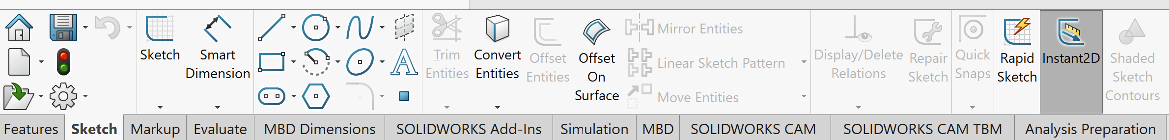
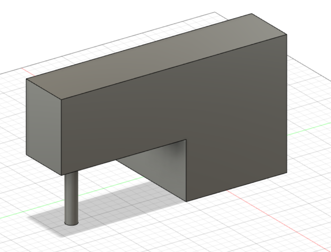
It was overwhelming and remained overwhelming for some time. After finishing the tutorial, I created a simple design that was a box:
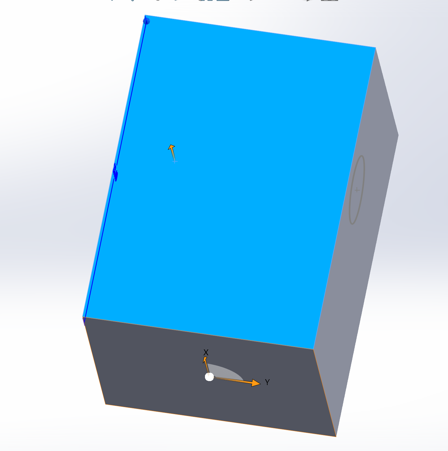
There was a few things I learned about SolidWorks but the knowledge that I took away the most was, in SolidWorks, start with Parts then you take those parts you created and put them together in Assembly. From there, you can create a drawing in Drawing of either a part or an assembly.
My Verdict On SolidWorks
SolidWorks is a power application. I can see its potential however, I did not find the user interface comfortable to work with. Also, the fact that it is primarily for Windows made the learning SolidWorks more difficult as I am not familiar with Windows. As a result, I decided not to keep SolidWorks and regain 19 GB of memory back.
Exploring SolidWorks XDesign
SolidWorks xDesign, also known as xDesign, is a browser-based design tool built on the 3DExperience Platofrm. You can learn more about xDesign on their website. xDesign is versatile due to it being a browser-based. Similar to exploring and learning SolidWorks, I used LinkedInLearning for assist in my development and understanding of the platform. I found a course called Learning SolidWorks xDesign by David Antanavige. The course was 1 hour and 29 minutes and it taught how to design parts with SolidWorks xDesign while exploring SolidWorks xDesign user interface, the how tos of SolidWorks xDesign, and creating models.
My experience with xDesign was less overwhelming and confusing than SolidWorks. However, the limitation I found was that it was dependent on stable internet connection. Nonetheless, my experience was okay. I was able to navigate through xDesign with the help of the tutorial.
Openning xDesign:
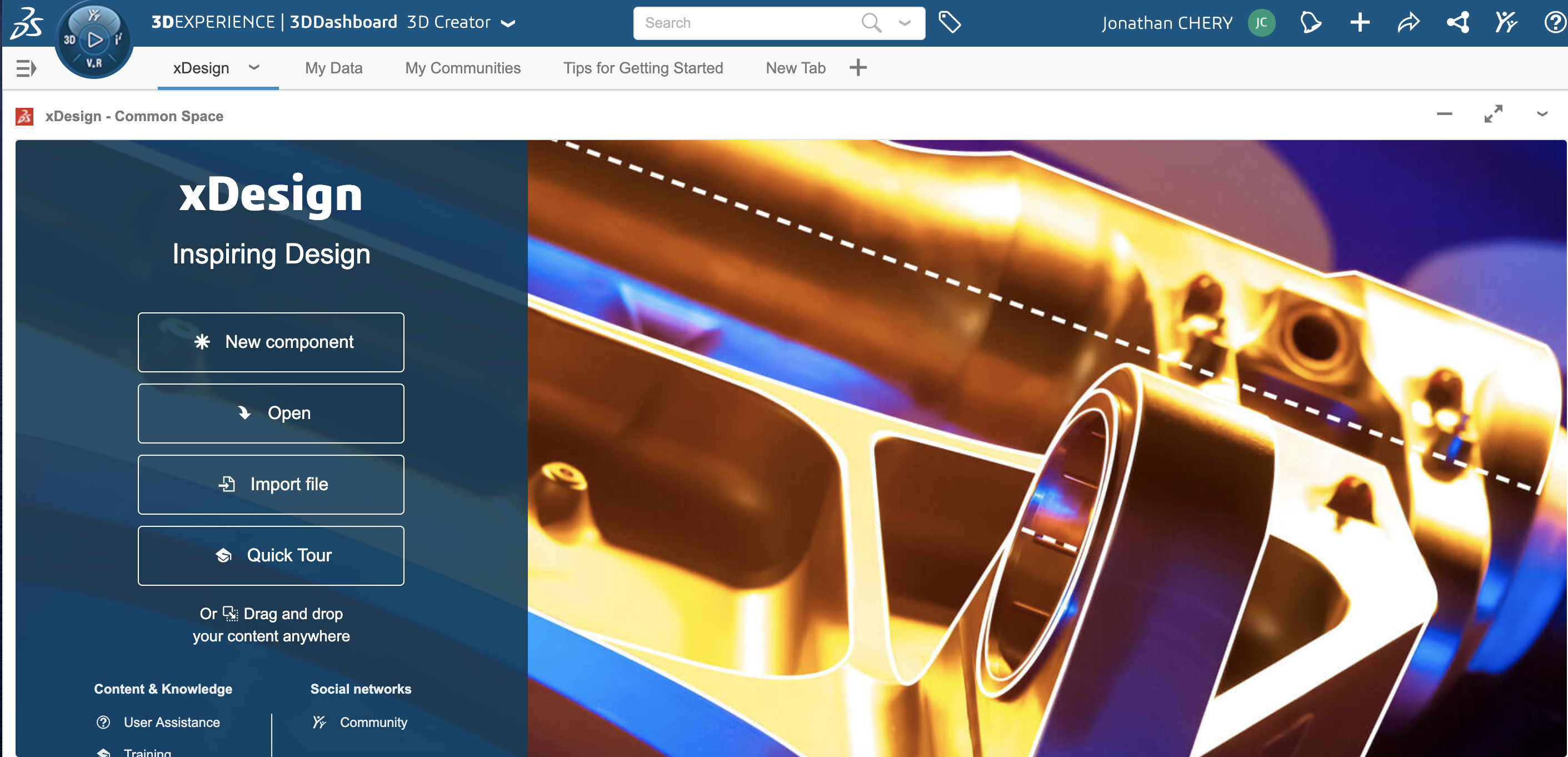
From there, I selected New Component in which I was introduced to the new environment. I like the environment as it was organized and user-friendly. I created a simple 2D-Design doing the following steps:
- Started in the Sketch Tab
- Selected Create or Edit Sketch
- Selected an axile and panel
- Selected Line
- Selected Square
- Selected Ellipse
The result came out to be:
My Verdict On xDesign
Thought SolidWorks xDesign had an easier user interface and user experience than SolidWorks. However, I do not think I will continue to use the product. I heard Fusion 360 is better and I am excited to explore the application.
Exploring AutoDesk Fusion 360
I heard a lot of good things about Fusion 360. Fusion 360 is an integrated CAD, CAM, CAE, and PCB software. Fusion 360 is a cloud-based application, similar to Adobe Creative Cloud. You can learn more about Fusion 360 on AutoDesk’s website.
To learn more about Fusion 360 and what it has to offer, I found a tutorial on LinkedIn Learning. The course I used to help me in this journey was Learning Fusion 360 by Taylor Hokanson. This course was 1 hour and 24 minutes long and it was basically a crash course of Fusion 360. On top of using LinkedIn Learning to learn about Fusion 360, I also spoke to team members and teachers for additional guidance. My team and teachers were a tremendous help in understanding the process of using Fusion 360. Playing around with Fusion 360 allowed me to create a simple design that I following from the LinkedIn Learning course:
My Verdict on Fusion 360
Fusion 360 was not difficult to comprehend. It does take some time getting use to it but, it was simple. The user interface and experience were well-designed and intuitive. I did not feel overwhelm from the design and functionalities. I believe that I will be staying with Fusion 360.
Miscellaneous Thoughs On CAD softwares
There are a few more application I wanted to explore such as:
Exploring Adobe Illustrator
Adobe Illustrator is an industry-standard vector graphics software that lets you create everything from web and mobile graphics to logos, icons, book illustrations, product packaging, and billboards. Also, note that Adobe Illustrator is part of Adobe’s Creative Cloud. To learn Adobe Illustrator, I used the LinkedIn Learning Adobe Illustrator 2021 Essential Learning. This course was helpful for a crash course of Adobe Illustrator however, because I do not have a Creative Cloud subscription, I only did a 7 day trial. I enjoyed using and learning Adobe Illustrator. It would be good to invest more time in learning Adobe Illustrator along with some of the other Creative Clouds applications.
Modeling My Final Project
I used Fusion 360 to develop my final project. As a reminder, my final project is a programmable smart button. In other words, a button that connects to the internet to control other devices connected to the internet. My inspiration is a car key fob or a keychain. The reason why this is my inspiration is because I find a key fob easy to use, conveniently placed on your keys, and easily accessible. With my inspiration in mind, I found some resource that can help guide me through the design of a key fob or key chain.
- Easy Key tag Fusion 360 tutorial 2020
- Making a Simple Keychain in Autodesk Fusion 360
- Design a Keychain With Fusion in 3 Steps
- Modelling a remote in Fusion 360
Additionally, I found Car Key Fob design that Franklin Turza. With a few edits, this would be a great key fob for my smart button.
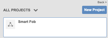
To develop my smart button remote, I followed the Modelling a remote in Fusion 360 tutorial. I started by opening Fusion 360 and create a New Project.
I created a New Sketch
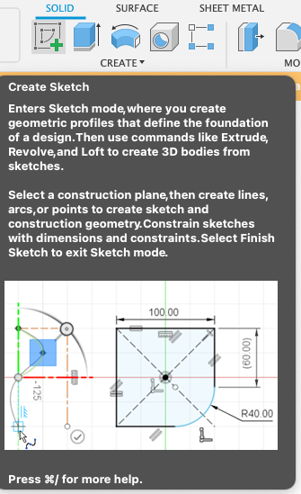
And placed that sketch on the Top of the panel.
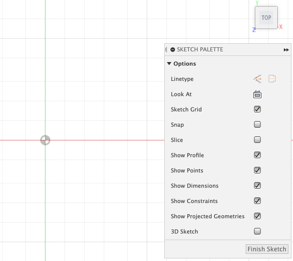
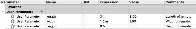
I created the following parameters by selecting Change Parameters under MODIFY :
- length : 3 inches
- width : 1.5 inches
- height : .5 inch
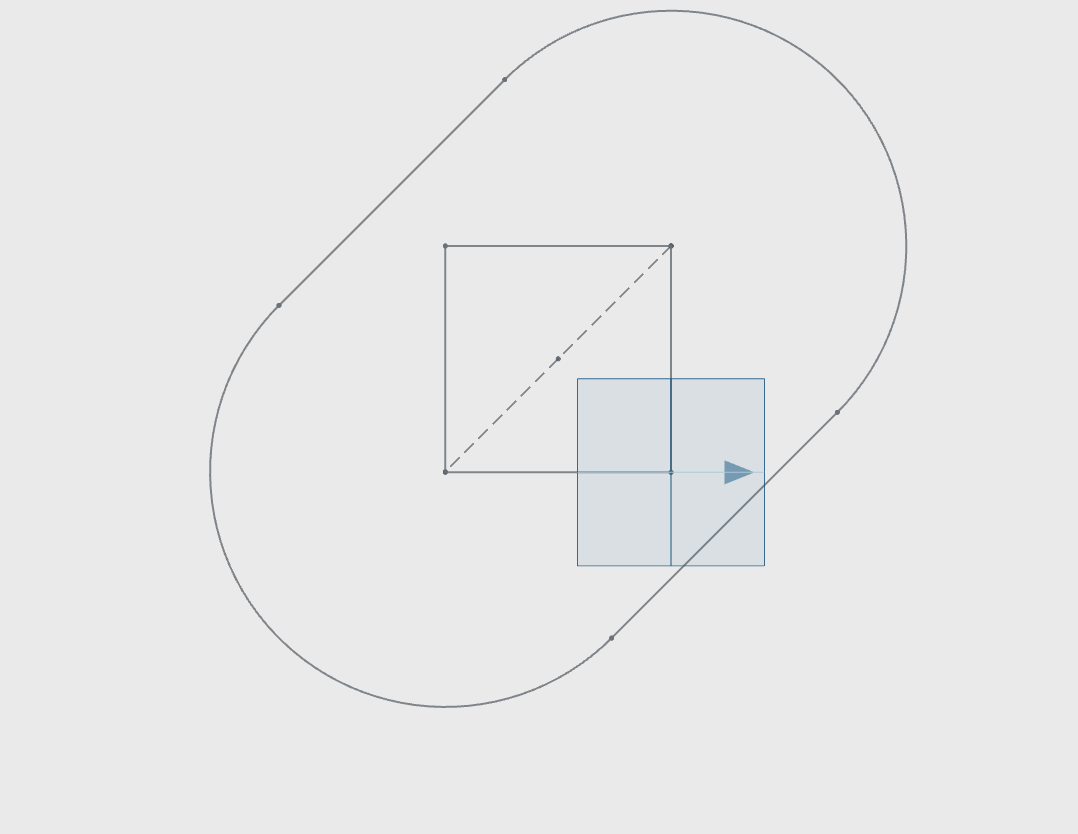
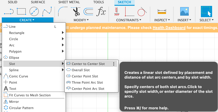
From there, I created a Center To Center Slot at the origin and to access that, I went to CREATE -> SLOT -> CENTER TO CENTER SLOT
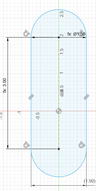
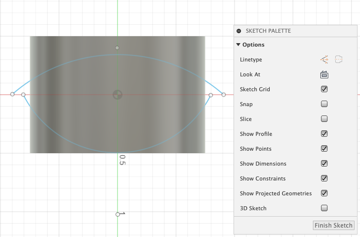
From there, I started my sketch. I inserted the length and width to be the parameters I created:
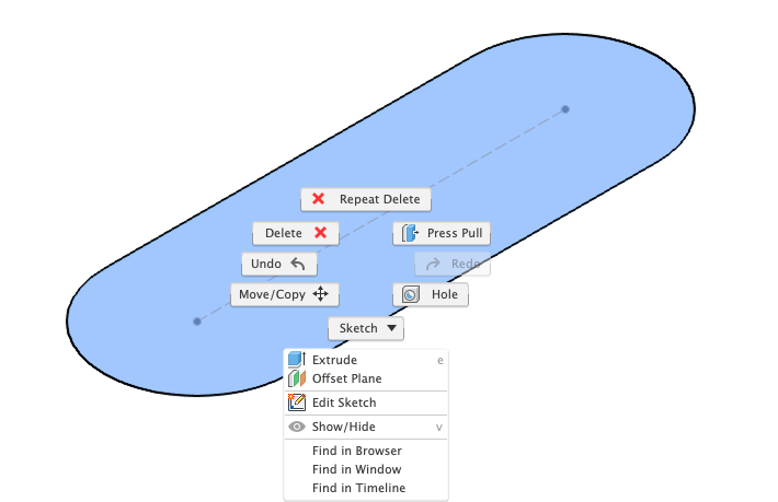
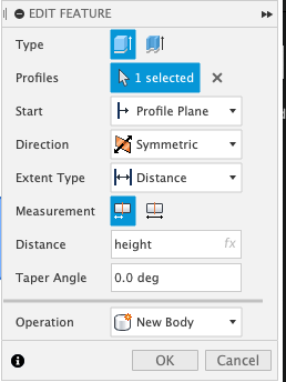
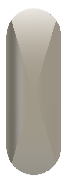
I finished the sketch and then extruded the result by selecting E or by selecting the sketch I want to extrude, right clicking it, and selected Extrude. I made the extrude to be the height I created in the parameters and I also made it symetrical:
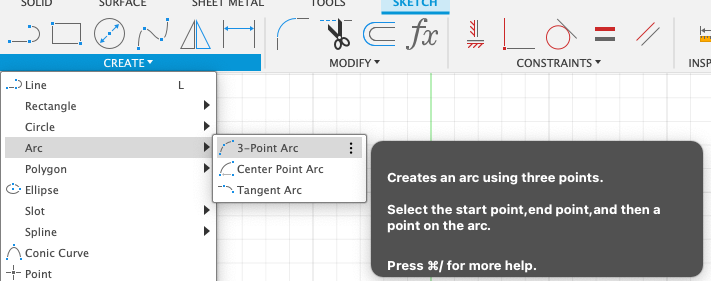
From there, I changed the orientation to the FRONT and started a New Sketch on its face. I selected a 3-Point Arc
Then using the 3-point arc, I created an arc on the front of my design:
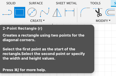
From there, I created a Rectangle by selecting the R key on my keyboard or by selecting a 2-point rectangle within CREATE:
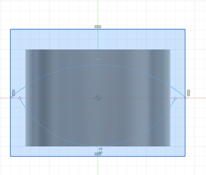
Then I created a Line by selecting the L key on my keyboard or by selecting a Line within CREATE:
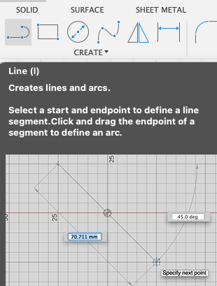
After creating my line, I drew a line on each dot that is shown in the design. This allowed me to do the following:
From there, I changed the orientation to:
Then extruded to the end of each side.
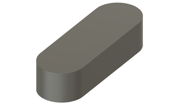
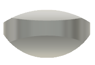
The result of the extrude was:
Now, I change the orientation to the right:

I created a new sketch the right side and selected a 3-point arc. The goal was to do a repeat of what I did previously to get the following result:
From there, I selected the rim of the remote:
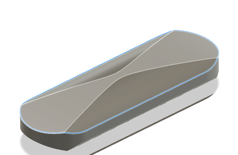
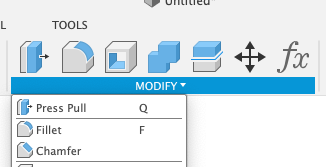
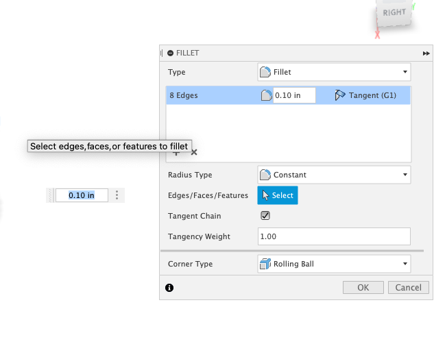
I selected the rim of the remote to add a fillet to it. To add fillet, press the key F or go to MODIFY > Fillet:
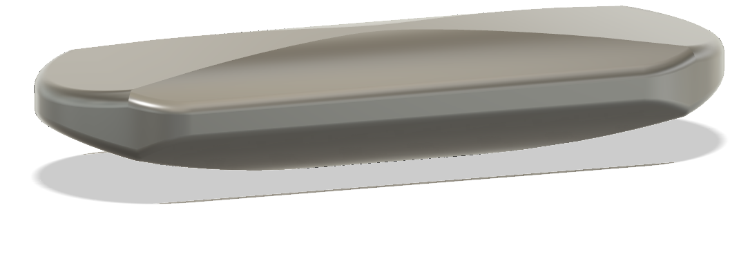
I also set a fillet for the bottom as well.
Now, to work on the top of the remote:
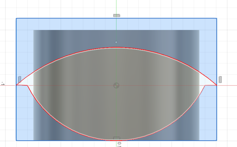
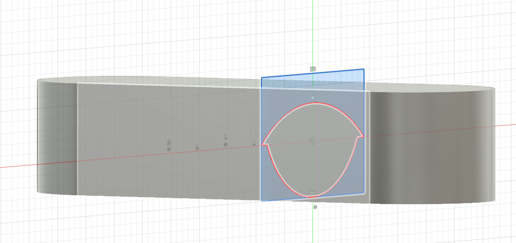
Looking at the top, the top of the remote was not flat. To flatten the top, I changed the orientation to be Left:
I then created a rectangle to intersect with the remote:
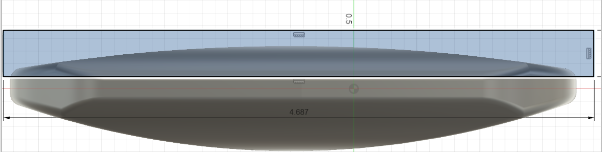
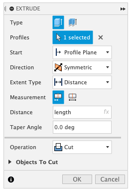
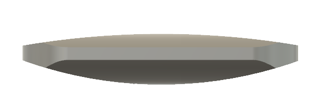
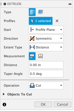
I extruded the rectangle, selected it to be symmetrical and then cut the remote from one side to the other:
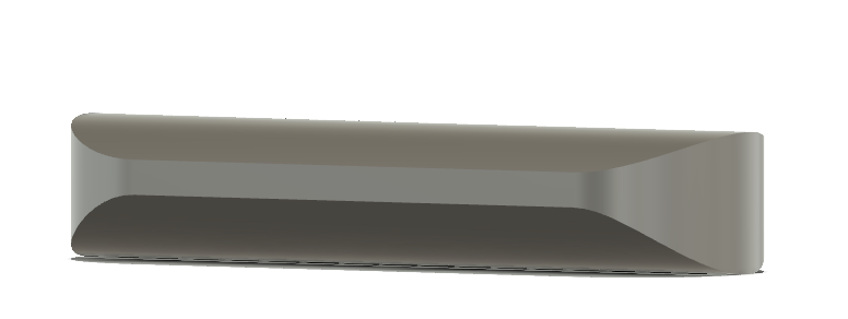
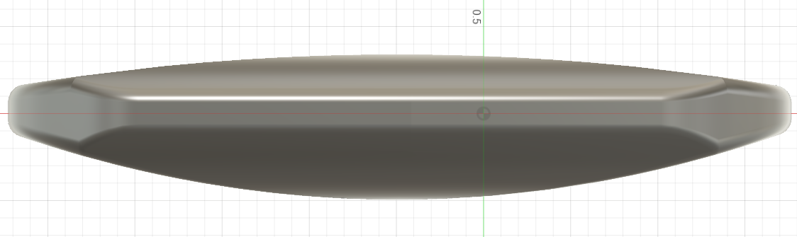
Now, looking at the top again, it is flat:

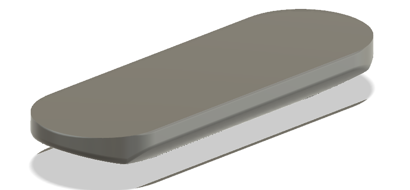
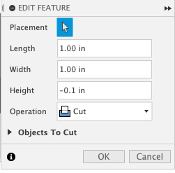
It is time to add a output screen, a button, and a key holder. I started with the output screen. Changing the orientation to the top of the remote, I created a box which can be found in CREATE:
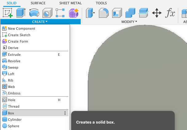
I placed the box on the upper top of the remote and made it an inch long and wide.
The result:
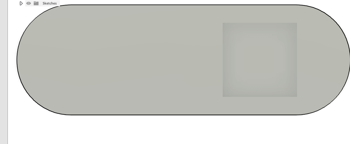
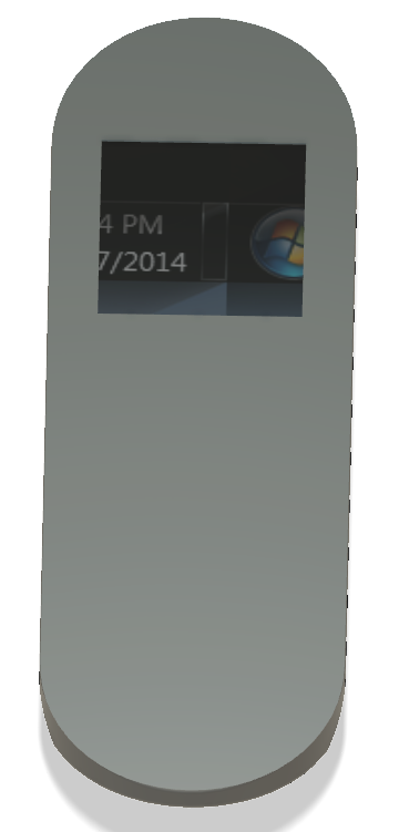
This box will be where the output screen will be placed. Here is an example using the Fusion 360’s Appearance feature found in MODIFY > Appearance or by pressing a:
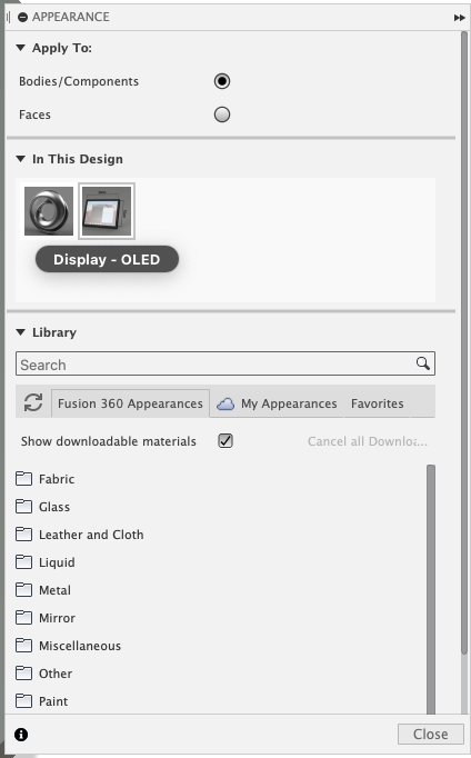
An example:
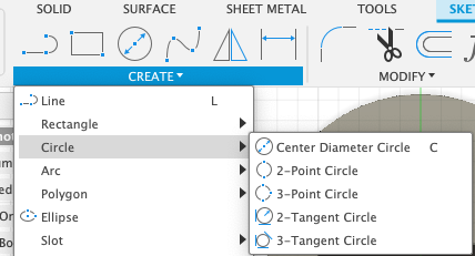
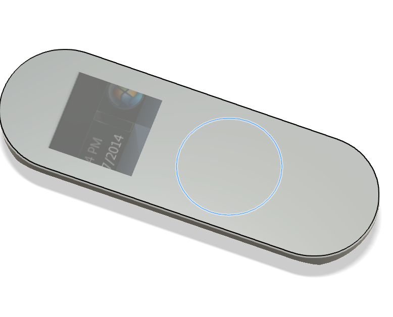
Now for the button. To add a button, I created a new sketch on the top face. I drew a circle which can be found in CREATE:
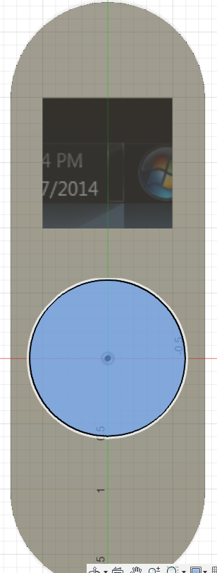
Once I drew my circle, I selected Split Body* which can be found in MODIFY**:
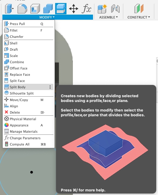
I selected the remote body to be the Body To Split and the circle to be the Splitting Tools:
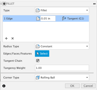
The next step is to make this button more viewable. To do so, I selected the circle outline and right click to open up the menu:

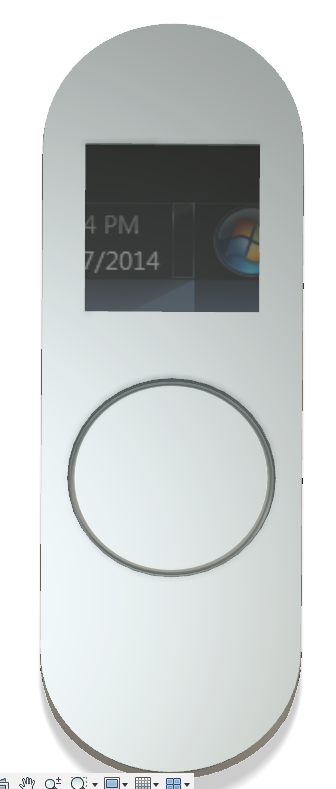
I then selected Press Pull and configured it to .05 inches:
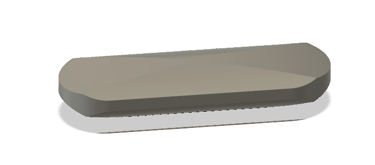
Here is the result:
Finally, I need to add a place to connect it to my keys or a chain to make it easily accesible. To do so, I created a hole at the bottom end of the top. I did so by slecting Hole within the CREATE panel:
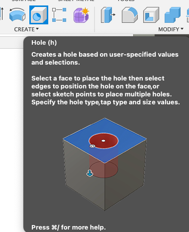
Once it was selected, I moved the hole towards the bottom end of the remote:
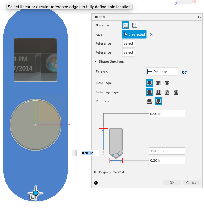
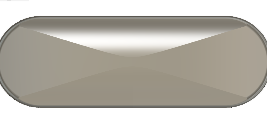
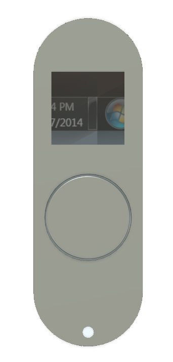
The hole is in the case you would like to have your smart remote/button on your keychain. The final result:
You can doanload the Fusion 360 files by clicking here -> Download .f3d