14. Interface and Application Programming
For this week individual assignment was to write an application that interfaces a user with an input &/or output device that we made. For the group assignment we needed to compare as many tool options as possible. I used three different softwares, Processing, Python Tkinter and MIT App Inventor.
Individual assignment
Processing
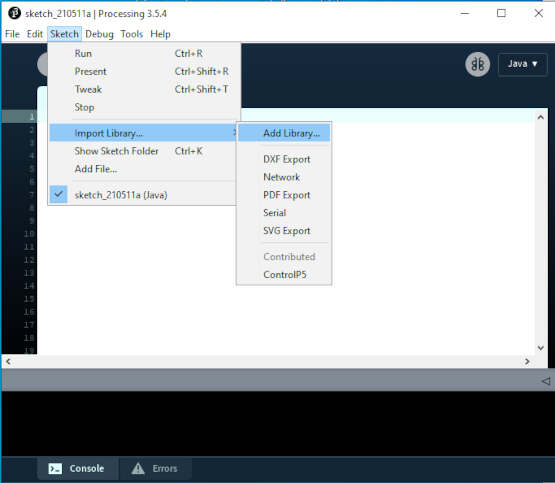
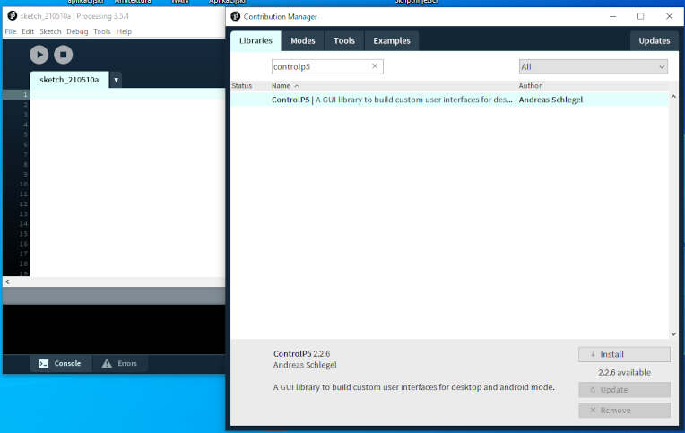
First software that I wanted to try is Processing. I downloaded Processing from official site, here. After I installed Processing I needed to include ControlP5, a GUI library to build custom user interfaces. I go to Sketch- > Import Library -> Add Library and than install ControlP5 library.
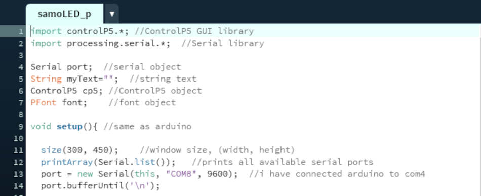
I started looking tutorials how to use Processing. Good starting point was FabLab Barcelona site and this youtube tutorial. Processing is somewhat similar to Arduino. It has a setup() and draw() function. Draw function is like loop in arduino. I wanted to write simple app to control LED from my PC. First I imported serial and GUI library and then created objects. In the void setup() we can set window size like 300x450px. Also I set parameters for serial communication. In my case FTDI adapter was on COM8.
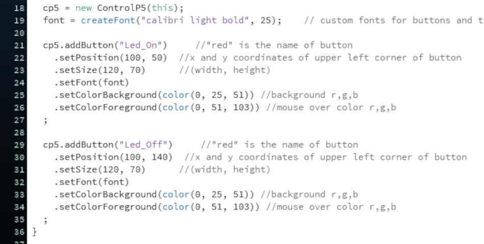
Then I created custom fonts and added two buttons, one is to turn LED on and one to turn off. Button is a part of ControlP5 library. I can set position of the button, size, background and foreground colors..
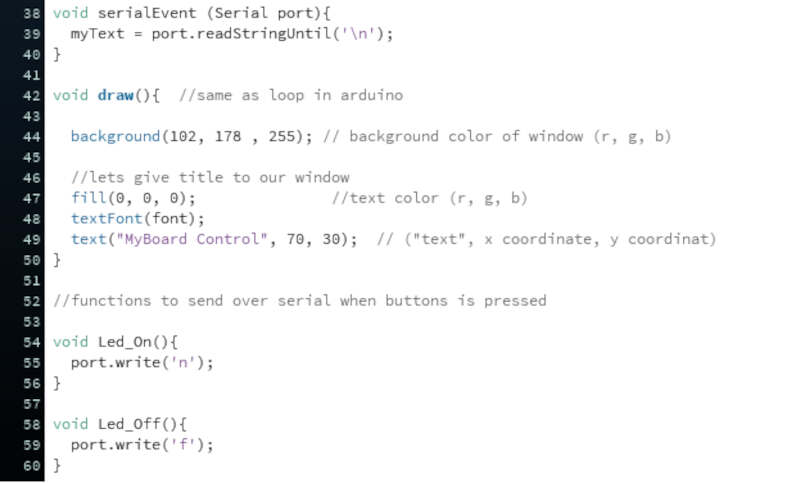
SerialEvent function reads data from my board. For this example it’s not needed but I will use it in the next examples. In the draw function which loops continuously I set background color, fill and custom text. Last thing is to add two functions to control LED. When we want to turn LED on it sends a ‘n’ character over serial and to turn off it sends a ‘f’ character. I think those functions needs to have the same name as the buttons name in order to work.
In Arduino I set the SoftwareSerial communication because I use ATtiny85 (PB0 and PB1). It reads the incoming data (character) and then turn the LED on or off.
#include <Mouse.h>
#include <SoftwareSerial.h>

SoftwareSerial TinySerial(1, 0); // RX, TX

int ledPin = 4;

void setup()
{
  TinySerial.begin(9600);
  pinMode(ledPin, OUTPUT);
}
void loop()
{
  if(TinySerial.available() > 0) {
    char ledState = TinySerial.read();
    if(ledState == 'n'){
      digitalWrite(ledPin, 1);
    }
    if(ledState == 'f'){
      digitalWrite(ledPin, 0);
    }

  }

}
import controlP5.*; //ControlP5 GUI library
import processing.serial.*;  //Serial library

Serial port;  //serial object
String myText="";  //string text
ControlP5 cp5; //ControlP5 object
PFont font;    //font object

void setup(){ //same as arduino

  size(300, 450);    //window size, (width, height)
  printArray(Serial.list());   //prints all available serial ports
  port = new Serial(this, "COM8", 9600);  //i have connected arduino to com4
  port.bufferUntil('\n');

  //lets add buton to empty window

  cp5 = new ControlP5(this);
  font = createFont("calibri light bold", 25);    // custom fonts for buttons and title

  cp5.addButton("Led_On")     //"red" is the name of button
    .setPosition(100, 50)  //x and y coordinates of upper left corner of button
    .setSize(120, 70)      //(width, height)
    .setFont(font)
    .setColorBackground(color(0, 25, 51)) //background r,g,b
    .setColorForeground(color(0, 51, 103)) //mouse over color r,g,b
  ;

  cp5.addButton("Led_Off")     //"red" is the name of button
    .setPosition(100, 140)  //x and y coordinates of upper left corner of button
    .setSize(120, 70)      //(width, height)
    .setFont(font)
    .setColorBackground(color(0, 25, 51)) //background r,g,b
    .setColorForeground(color(0, 51, 103)) //mouse over color r,g,b
  ;
}

void serialEvent (Serial port){
  myText = port.readStringUntil('\n');
}

void draw(){  //same as loop in arduino

  background(102, 178 , 255); // background color of window (r, g, b)

  //lets give title to our window
  fill(0, 0, 0);               //text color (r, g, b)
  textFont(font);
  text("MyBoard Control", 70, 30);  // ("text", x coordinate, y coordinat)
}

//functions to send over serial when buttons is pressed

void Led_On(){
  port.write('n');
}

void Led_Off(){
  port.write('f');
}
You can see a working video here.
I used my board based on ATtiny85 that I made in Electronic Design week.
Next thing I wanted to try is control a brightness of LED through PWM. I added a slider in Processing and set the values from 0 to 255. Default value I set to half, 125. Each time when we set value, it sends those value over serial with the help of led function. My board receives that value and uses analogWrite function to set the brightness of LED.
#include <Mouse.h>
#include <SoftwareSerial.h>

SoftwareSerial TinySerial(1, 0); // RX, TX

int ledPin = 4;
int val = 125;

void setup()
{
  TinySerial.begin(9600);
  pinMode(ledPin, OUTPUT);
  analogWrite(ledPin, val);
}
void loop()
{
  if(TinySerial.available()){ //if data available
    int val = TinySerial.read();
    analogWrite(ledPin, val);
  }
}
import controlP5.*; //library
import processing.serial.*; //library
Serial port; //do not change
ControlP5 cp5; //create ControlP5 object
PFont font;
//int led;

void setup() {

  size(400, 400); //window size, (width, height)
  port = new Serial(this, "COM8", 9600); //connected arduino port
  cp5 = new ControlP5(this); //do not change
  font = createFont("calibri light bold", 25);

  cp5.addSlider("led")
    .setPosition(170, 70) //x and y upper left corner
    .setSize(50, 250) //(width, height)
    .setRange(0, 255) //slider range low,high
    .setValue(125) //start val
    .setColorBackground(color(0, 0, 255)) //top of slider color r,g,b
    .setColorForeground(color(0, 255, 0)) //botom of slider color r,g,b
    .setColorValue(color(255, 255, 255)) //vall color r,g,b
    .setColorActive(color(255, 0, 0)) //mouse over color
    ;
}

void draw() {

  background(0, 0, 0); // background color of window (r, g, b)
  textFont(font);
  text("MyBoard PWM Control", 90, 30);
}

void led(int led)
{
  port.write(led);
}
You can see results in a video bellow
So, next is inputs. I wanted to make simple GUI to check the state of a push button. Here I’m using seialEvent function to read incoming string and display it in a main window. In arduino I set the following: when the push button is pressed it sends „Button pressed“ and when it’s not „Button depress“. You can see Arduino and Processing code bellow and also a video how it works.
#include <Mouse.h>
#include <SoftwareSerial.h>

SoftwareSerial TinySerial(1, 0); // RX, TX

int buttonPin = 3;

void setup()
{
  TinySerial.begin(9600);
  pinMode(buttonPin, INPUT);
}
void loop()
{
  if(TinySerial.available() > 0) {

    int buttonState = digitalRead(buttonPin);
    if(buttonState == LOW){
      TinySerial.println("Button is pressed");
    } else TinySerial.println("Button is depressed");

  }

}
import processing.serial.*;

Serial port;
String text="";
PFont font;

void setup() {
  size(400, 400);
  port = new Serial(this, "COM8", 9600);
  port.bufferUntil('\n');
  font = createFont("Georgia Bold", 20); //font for buttons and title
}


void draw() {
  background(0, 0, 0);
  text("MyBoard push button", 100, 50);
  fill(255, 255, 255);
  text(text, 120, 120);
  textSize(20);
  fill(#4B5DCE);
}

void serialEvent (Serial port) {
  text = port.readStringUntil('\n');
}
I wanted to include a processing sketch that I made in input devices week where I connected ultrasonic sensor to my board. I used processing to display a distance from an object. All the calculations are done in arduino and then sent over serial to Processing. SerialEvent function in Processing reads the data (distance) and display on screen.
#include <Mouse.h>
#include <SoftwareSerial.h>

SoftwareSerial TinySerial(1, 2); // RX, TX

const int trigpin = 3; //connection between
const int echopin = 4;  //ATtiny85 and sonar
long duration;
int distance;
void setup()
{
  pinMode(trigpin,OUTPUT);
  pinMode(echopin,INPUT);
  TinySerial.begin(9600);

}
void loop()
{
  digitalWrite(trigpin,HIGH);
  delayMicroseconds(10);      //send 10us pulse
  digitalWrite(trigpin,LOW);
  duration=pulseIn(echopin,HIGH);
  distance = duration*0.034/2;  //calculate distance
  TinySerial.println(distance); //display distance over serial
}
import processing.serial.*;
Serial myPort;
String data="" ;
PFont  myFont;
void setup()
{
size(1366,900); // size of processing window
background(0);// setting background color to black
myPort = new Serial(this, "COM3", 9600);
myPort.bufferUntil('\n');
}
void draw()
{
  background(0);
  textAlign(CENTER);
  fill(255);
  text(data,820,400);
  textSize(100);
  fill(#4B5DCE);
  text("              Distance :        cm",450,400);
  noFill();
  stroke(#4B5DCE);
}
void serialEvent(Serial myPort)
{

  data=myPort.readStringUntil('\n');
}
Python Tkinter
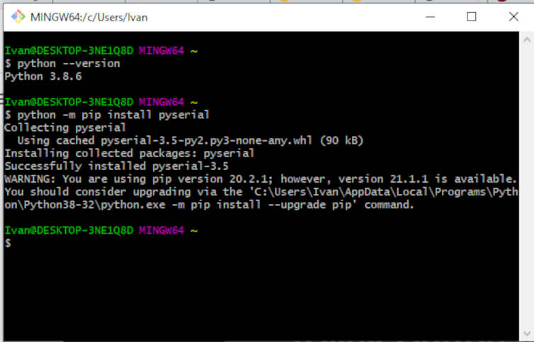
Next thing I wanted to try is Python and Tkinter. Tkinter is Python’s de-facto standard GUI (Graphical User Interface) package. Tkinter is not the only GuiProgramming toolkit for Python. It is however the most commonly used one. Tkinter comes with Python 3. First I check the version of Python by running:
python –-version
After that I needed to instal Python serial port extension called pyserial in order to communicate with my board. I entered:
python -m pip install pyserial
I opened Python shell and go to file -> new to write python code. I found some good tutorials for Tkinter, here and here. It’s somewhat similar to Processing. I import pyserial and tkinter, set the com port and speed. I defined two function, one to turn on LED and one to turn off LED. Root is responsible to create a window with label. The size of a window is set through root.geometry. Positions of the buttons is set through grid properties. This script sends ‘o’ and ‘x’ to control a LED when we press a corresponding button. Arduino reads serial characters and then turn on or off the LED. You can see codes and video bellow.
import serial
from tkinter import *
import tkinter as tk

commPort = 'COM8'
ser = serial.Serial(commPort, baudrate = 9600, timeout = 1)

def turnOnLED():
    ser.write(b'o')

def turnOffLED():
    ser.write(b'x')

# creating tkinter window
root = Tk()
root.title('LED control GUI')

btn_On= tk.Button(root, text="Turn On LED", command=turnOnLED)
btn_On.grid(row=2, column=0)

btn_Off = tk.Button(root, text="Turn Off LED", command=turnOffLED)
btn_Off.grid(row=2, column=1)

root.geometry("350x350")
root.mainloop()
#include <Mouse.h>
#include <SoftwareSerial.h>

SoftwareSerial TinySerial(1, 0); // RX, TX

int ledPin = 4;

void setup()
{
  TinySerial.begin(9600);
  pinMode(ledPin, OUTPUT);
}
void loop()
{
  if(TinySerial.available() > 0) {
    char ledState = TinySerial.read();
    if(ledState == 'o'){
      digitalWrite(ledPin, 1);
    }
    if(ledState == 'x'){
      digitalWrite(ledPin, 0);
    }

  }

}
Group Assignment
For this I used MIT App Inventor. It seems like a cool thing to make android apps and does not require an installation. MIT App Inventor is an intuitive, visual programming environment that allows everyone – even children – to build fully functional apps for smartphones and tablets. I go to App Inventor site and clicked create apps. I sign in with my google account. I started making a simple talking app.

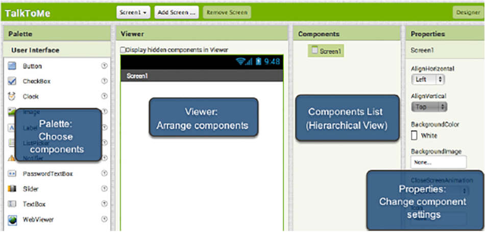
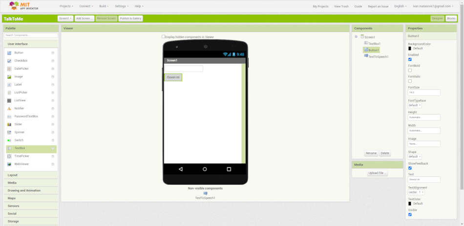
When I started a new project App Inventor opens the Designer window. The “Designer” is where you create the Graphical User Interface (GUI) or the look and feel of your app. You choose components like Buttons, Images, and Text boxes, and functionalities like Text-to-Speech, Sensors, and GPS (img source: appinventor.mit.edu).
I added text input, button and one non-visible component TextToSpeech. I also changed some properties of text input and button like button text and text input hint. Then I switched to Blocks Editor. The Blocks Editor is where we program the behavior of our app.
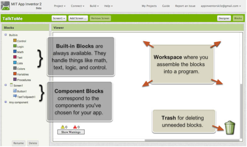
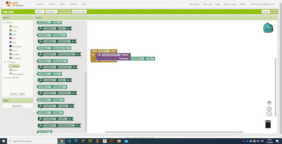
I assemble blocks to do the following, when we type some words in text input, function TextToSpeech pronounce them.
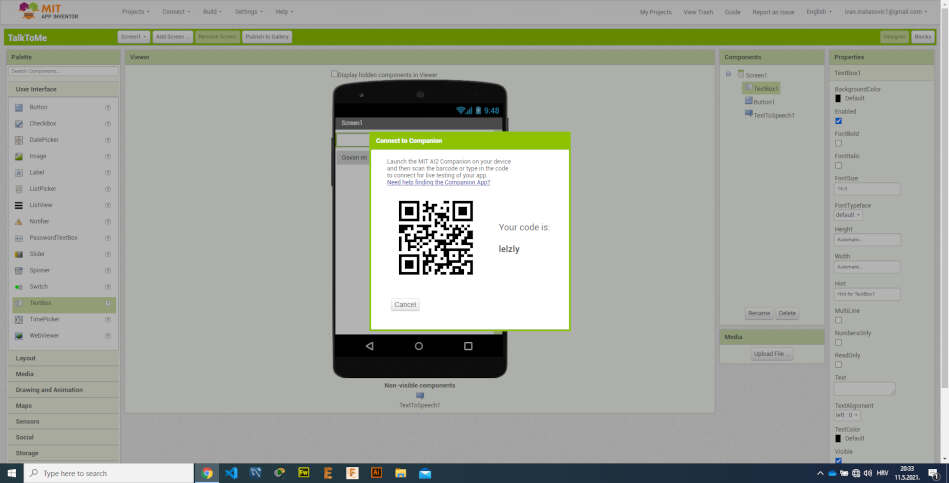
To test the app we have different options. I used AI Companion. I needed to install MIT AI2 Companion to my phone from Play Store.
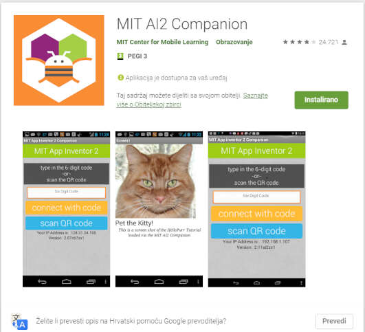
When I clicked on AI Companion, App Inventor generate some QR code that I scan with Companion app and then app runs on my phone. I made a video bellow.