4. Electronics production
This week is all about electronic production and milling. For the Individual assignment we had to make an in-circuit programmer that includes a microcontroller by milling and stuffing the PCB, we had to test it and optionally try other PCB processes. For the group assignment we had to characterize the design rules of our PCB production process.
Individual assignment
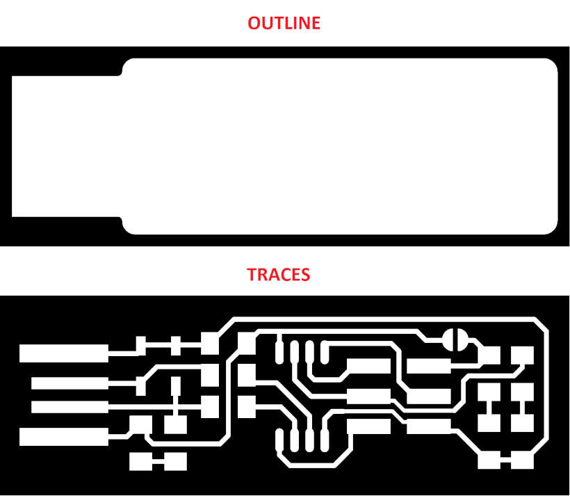
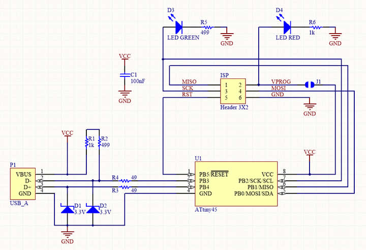
For the individual assignment I decided to make Brian’s FabTinyISP programmer based on ATtiny45. I downloaded traces and outlines png’s from his site.
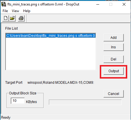
Milling machine that we used is Roland Modela MDX-15. First thing we try is to install all the necessary drivers and software for Roland but we had no success. After spending some time reading and searching on the Internet for solution we came across this site. First I downloaded and installed ME-US3 driver, that’s the cable for connecting Roland to PC (DB25 to USB). Then I downloaded and installed Roland driver for Windows 10. For sending RML files I used DropOut, can be found here. Roland uses RML file to work. That’s Roland proprietary file.
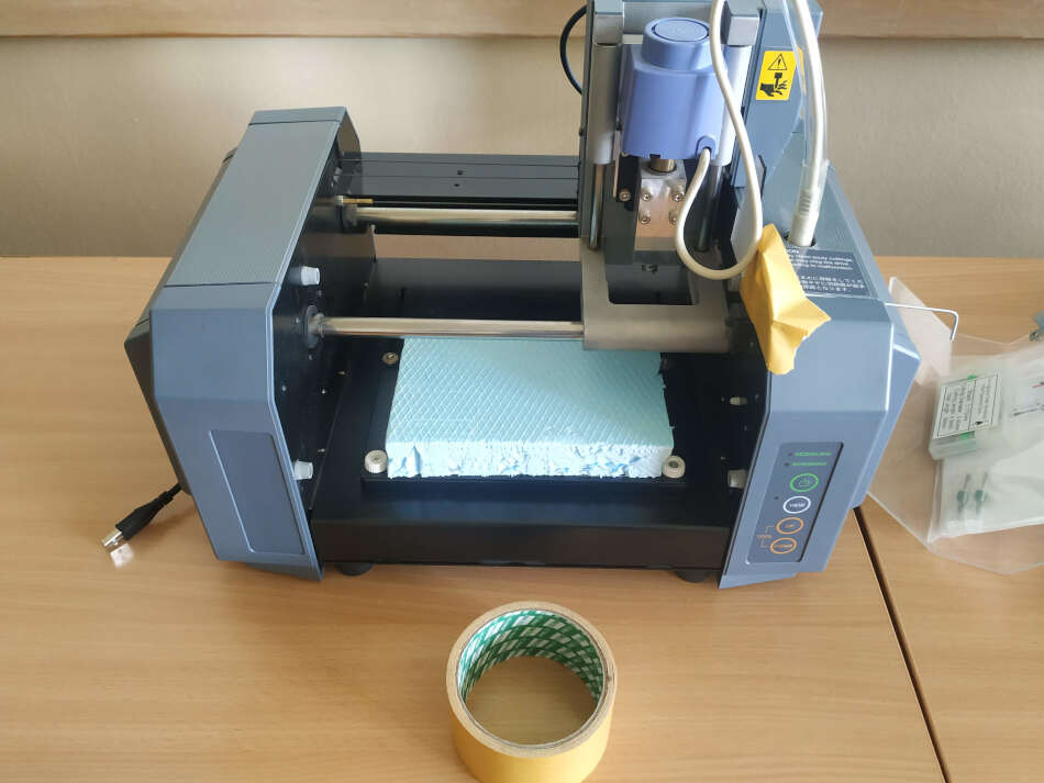
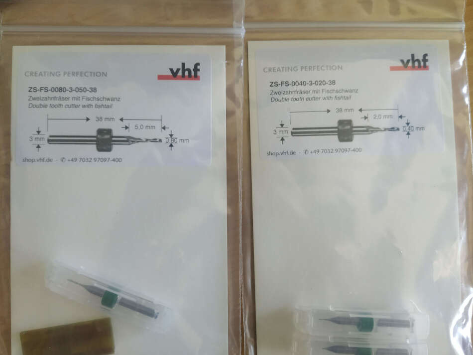
For the sacrificial layer I cut some XPS foam. On that I places PCB with double sided tape. The tool we used for traces milling is 0.4mm flat end mill and for the milling outline 0.8mm flat end mill. You can see it in a picture bellow.
Now we need to prepare files for milling. I used modsproject for setting the parameters. So, I go to modsproject and select MDX mill -> PCB program. There was a lot of windows and parameters but our instructors from Barcelona explained us what we need to set. First thing I added a save module so that I can save RML file for later.
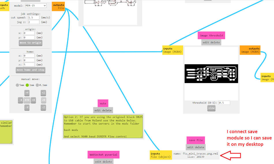
Next thing I opened a png where the traces are. From the Set PCB defaults (mm) I selected mill traces (1/64’‘). In mill raster 2D and Roland section I set the following parameters. You can see it in a picture bellow.
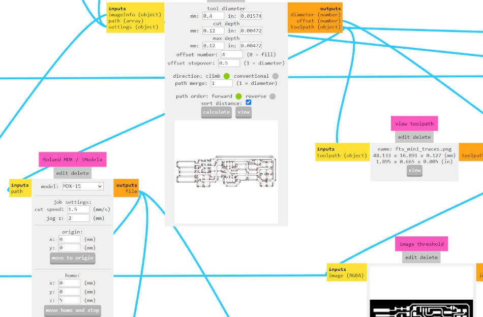
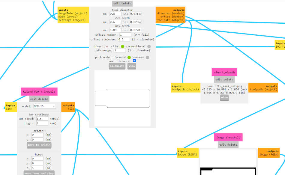
Speed was set to 1.5mm/s because I never used this machine before. I know that for new end mills can go as high as 3-4mm/s. Z jog I set to 2 mm. It should not be zero. Tool diameter I set 0.4mm. Offset I set to 0 to mill all the copper (first I set it to 4 but later chaged). When I set all the parameters I select calculate and than it’s saved on my desktop. After that I opened a png where the outlines are. I selected mill outline (1/32’‘) default and changed tool diameter to 0.8mm, max depth 1.85mm to be sure to cut layer beneath pcb. Cut depth of one pass is 0.6mm. Parameters for Roland is set like before. Click calculate and save.
Now I have two RML file. I previously attach PCB on XPS with double sided tape. I than opened DropOut and selected the traces RML and than Output.
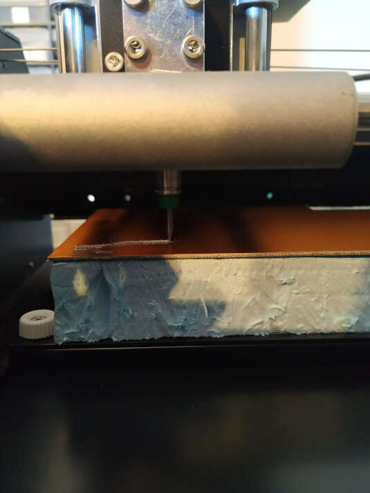
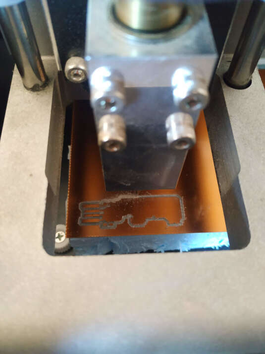
Roland started milling the traces and than after couple of minutes my end mill broke. I did not change the end mill. I started again with broken end mill, I know it can be done even with a broken end mill. This is the result I got.
After some sanding chips are removed but I accidentally break one line. Later I fix that line by soldering wire.
I gather all the components and started soldering. Components that I use are:
- 1x ATtiny85
- 2x 1kΩ resistors
- 2x 470Ω resistors
- 2x 47Ω resistors
- 2x 3.3v zener diodes
- 1x red LED
- 1x green LED
- 1x 100nF capacitor
- 1x 2x3 pin header
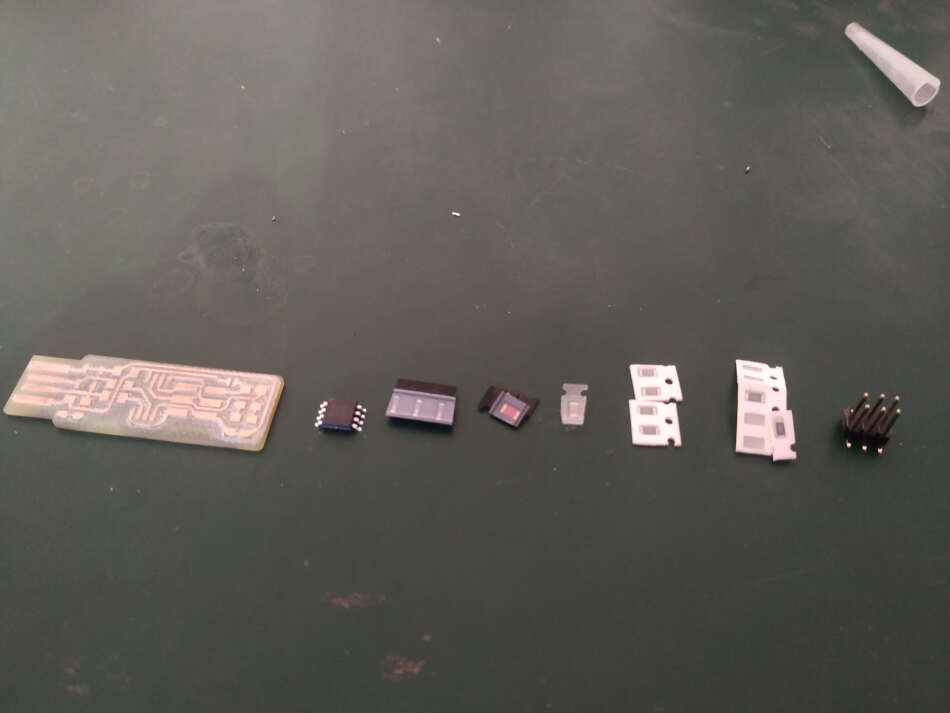
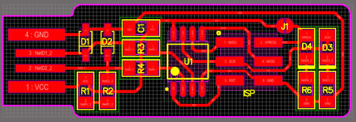
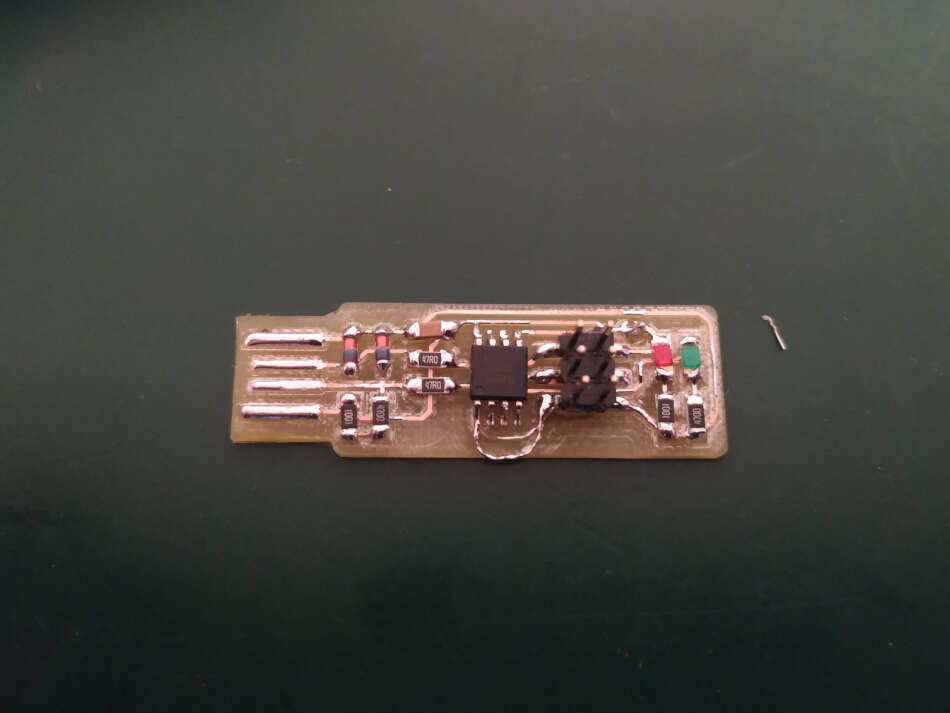
I followed schematic and PCB layout to assemble the programmer.
After I soldered all the components I needed to fix one line that has no continuity. I grab a piece of wire and soldered both ends. I examine it with multimeter and it was good.
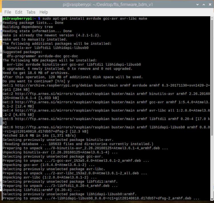
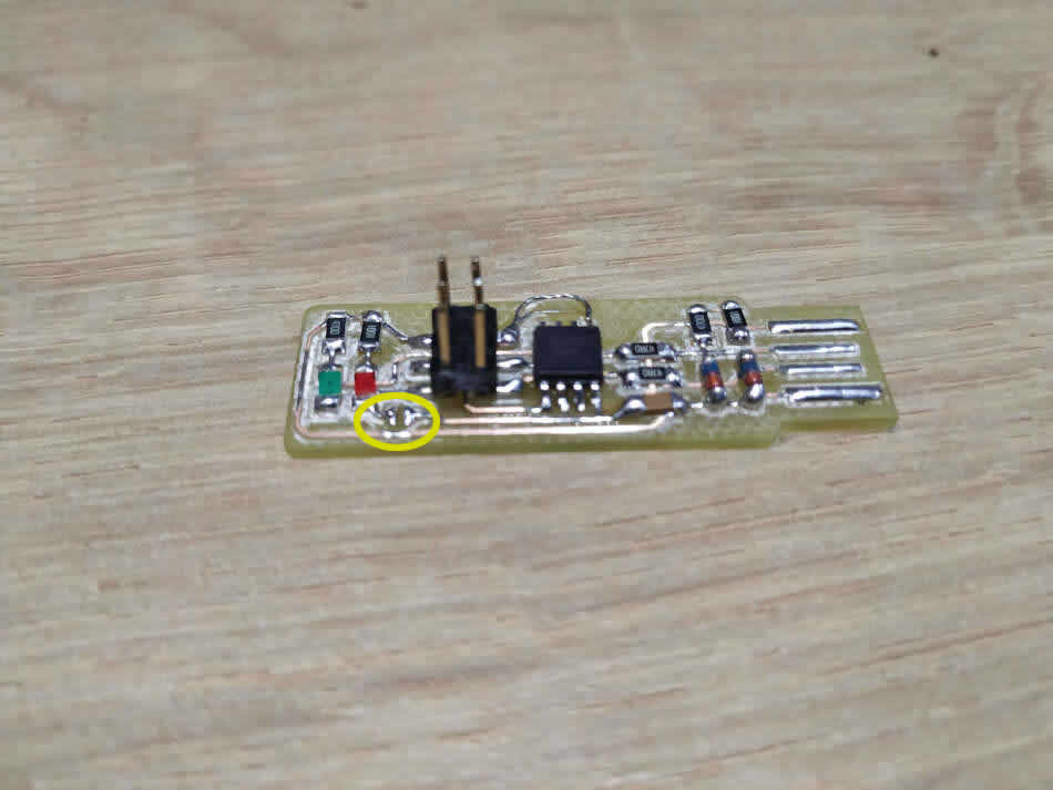
I also make a solder bridge near ISP header. This temporarily connects VCC to the Vprog pin on the ISP header so that the header can be used to program the tiny85. To program the firmware onto my board, I needed to set up my development environment. The easiest way to do is under Linux, so I used my Raspberry Pi 3 for that.
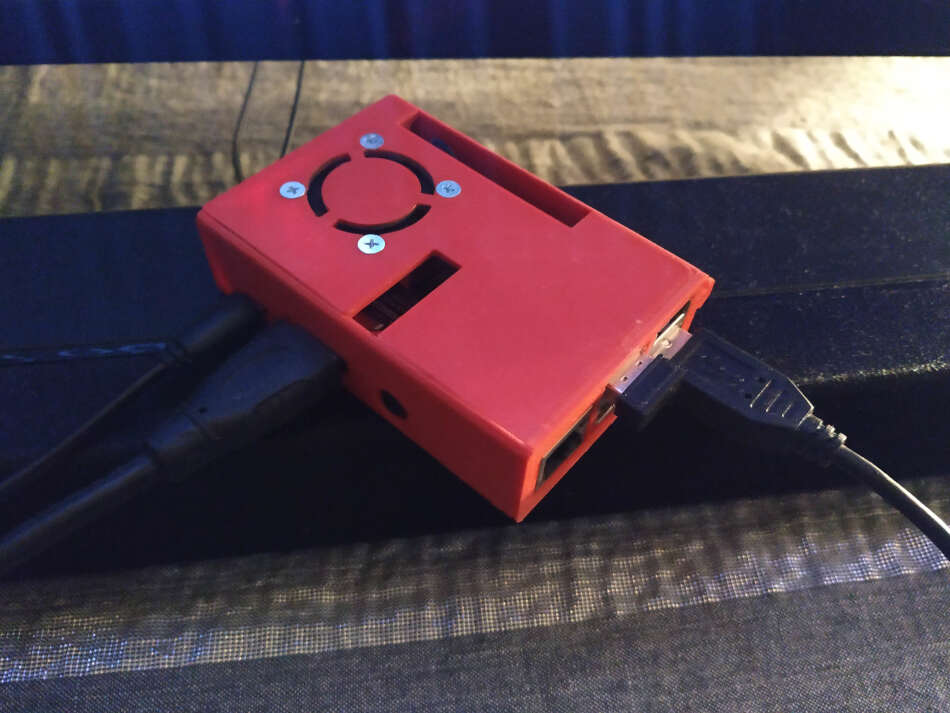
I opened a terminal and type the following to get all the tools.
sudo apt install avrdude gcc-avr avr-libc make
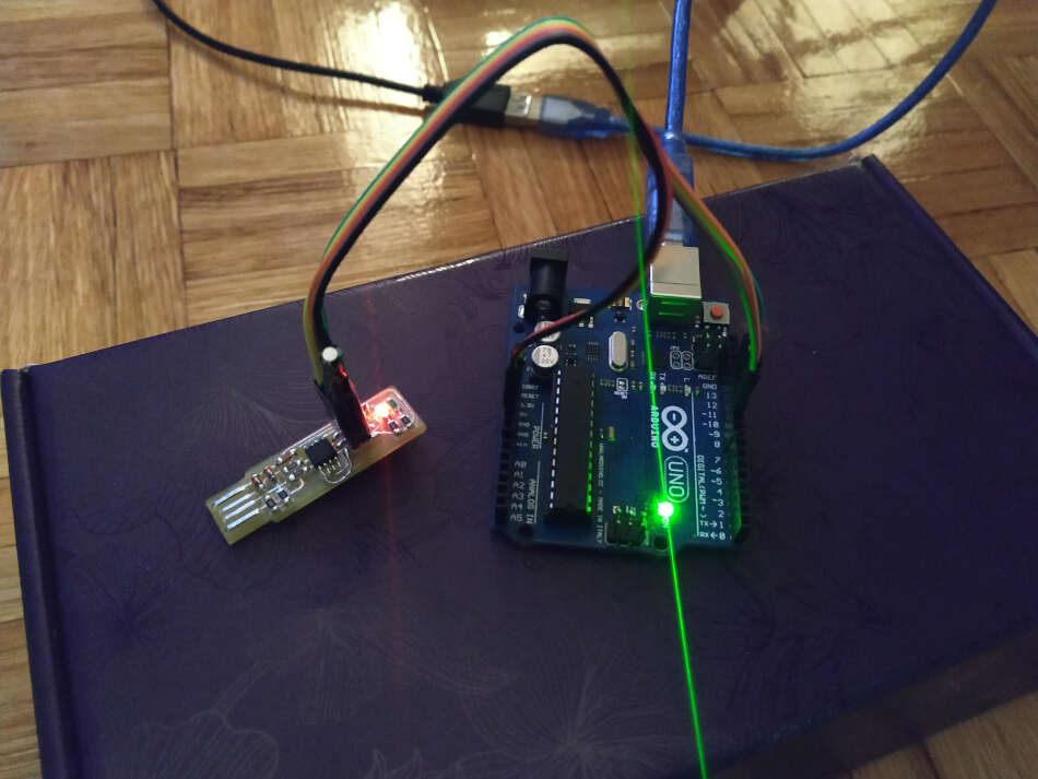
I download the source code from Brian’s site. First thing I needed to do is to modify the MAKEFILE. For me this was the most difficult part. I dont have AVRISP programmer so I used Arduino Uno. I previously added ATtiny44/45 board support and uploaded ArduinoISP sketch. Arduino is used as ISP.
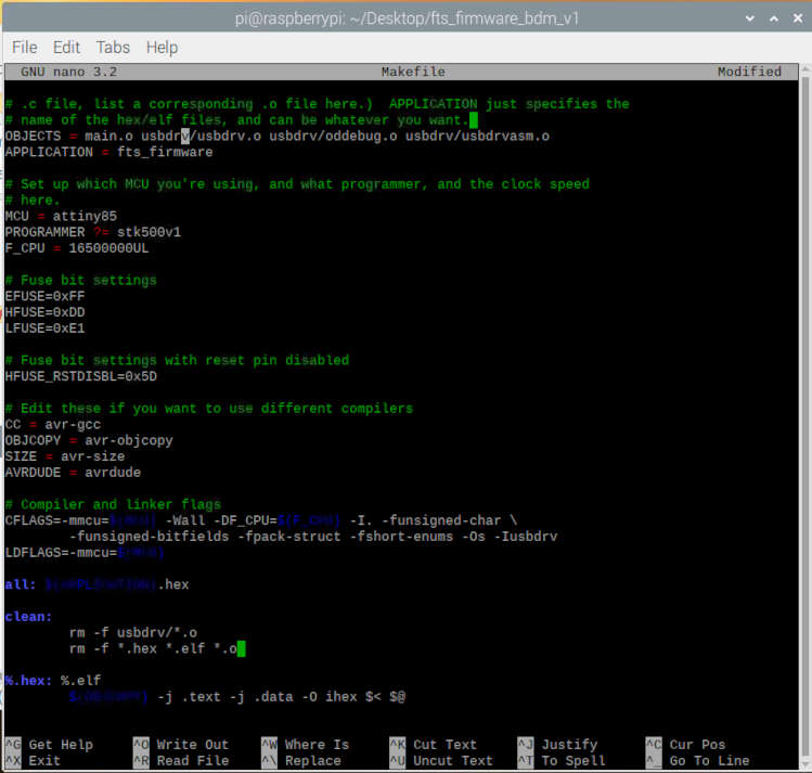
So, back to MAKEFILE. I open this with nano and after some trials and errors I successfully modified the MAKEFILE. I added port and upload rate and also included that in flash and fuses section bellow. MAKEFILE can be seen here:
# Generic AVR Makefile - Adapted for FabTinyStar
# Brian Mayton <bmayton@media.mit.edu>
#
# 'make' builds the .hex file.
# 'make flash' uses the programmer to load it onto the target chip.
# 'make fuses' programs the fuse bits on the target chip.
# 'make rstdisbl' blows the reset fuse.
# 'make clean' removes all autogenerated files.

# OBJECTS should list all of the object files for the program (e.g. for each
# .c file, list a corresponding .o file here.)  APPLICATION just specifies the
# name of the hex/elf files, and can be whatever you want.
OBJECTS = main.o usbdrv/usbdrv.o usbdrv/oddebug.o usbdrv/usbdrvasm.o
APPLICATION = fts_firmware

# Set up which MCU you're using, and what programmer, and the clock speed
# here.
MCU = attiny85
PROGRAMMER ?= stk500v1
F_CPU = 16500000UL
PORT = /dev/ttyACM0
UPLOAD_RATE = 19200


# Fuse bit settings
EFUSE=0xFF
HFUSE=0xDD
LFUSE=0xE1

# Fuse bit settings with reset pin disabled
HFUSE_RSTDISBL=0x5D

# Edit these if you want to use different compilers
CC = avr-gcc
OBJCOPY = avr-objcopy
SIZE = avr-size
AVRDUDE = avrdude

# Compiler and linker flags
CFLAGS=-mmcu=$(MCU) -Wall -DF_CPU=$(F_CPU) -I. -funsigned-char \
    -funsigned-bitfields -fpack-struct -fshort-enums -Os -Iusbdrv
LDFLAGS=-mmcu=$(MCU)

all: $(APPLICATION).hex

clean:
    rm -f usbdrv/*.o
    rm -f *.hex *.elf *.o

%.hex: %.elf
    $(OBJCOPY) -j .text -j .data -O ihex $< $@

$(APPLICATION).elf: $(OBJECTS)
    $(CC) $(LDFLAGS) -o $@ $^
    $(SIZE) -C --mcu=$(MCU) $@

%.o: %.c
    $(CC) $(CFLAGS) -c $< -o $@

%.o: %.S
    $(CC) -x assembler-with-cpp $(CFLAGS) -c $< -o $@

flash: all
    $(AVRDUDE) -p $(MCU) -c $(PROGRAMMER) -P $(PORT) -b $(UPLOAD_RATE) -e \
        -U flash:w:$(APPLICATION).hex

fuses:
    $(AVRDUDE) -p $(MCU) -c $(PROGRAMMER) -P $(PORT) -b $(UPLOAD_RATE)  \
        -U lfuse:w:$(LFUSE):m -U hfuse:w:$(HFUSE):m \
        -U efuse:w:$(EFUSE):m

rstdisbl:
    $(AVRDUDE) -p $(MCU) -c $(PROGRAMMER) -P $(PORT) -b $(UPLOAD_RATE)  \
        -U lfuse:w:$(LFUSE):m -U hfuse:w:$(HFUSE_RSTDISBL):m \
        -U efuse:w:$(EFUSE):m

.PHONY: all clean install fuses
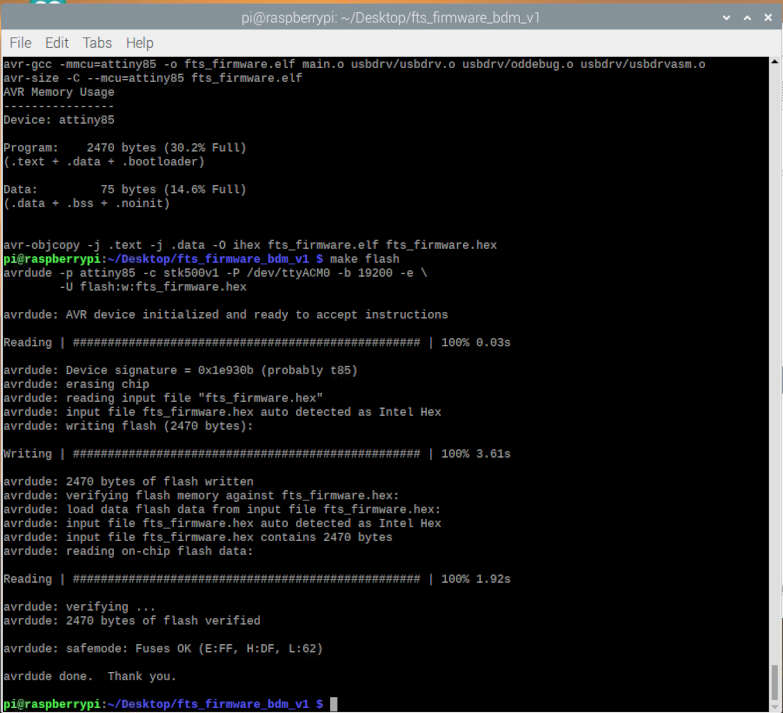
To obtain hex file I run
make
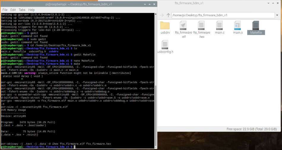
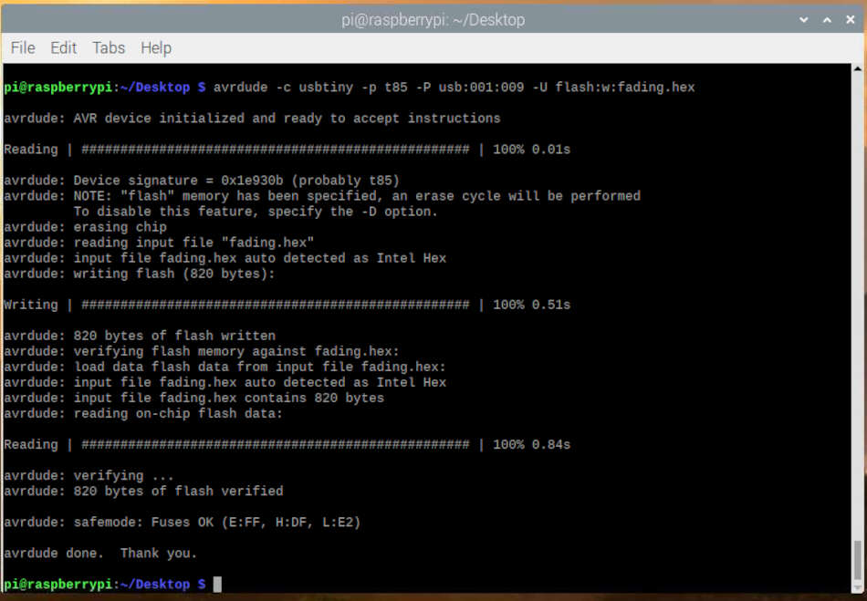
To flash the microcontroller I typed
make flash
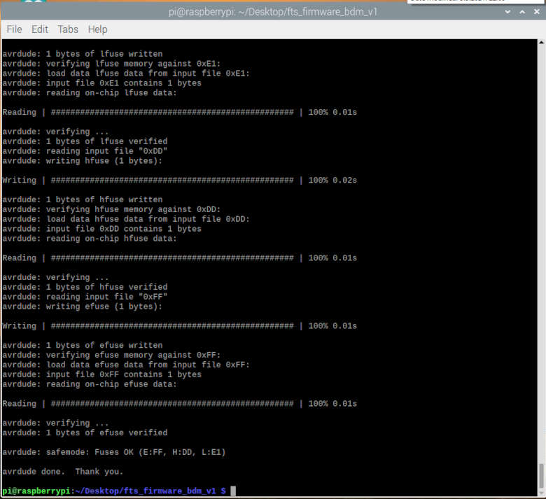
Than I run the make fuses command. This will set up all of the fuses except the one that disables the reset pin.
make fuses
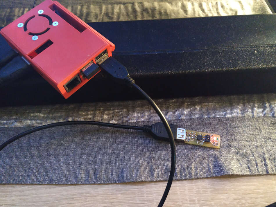
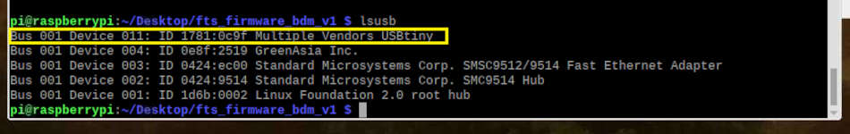
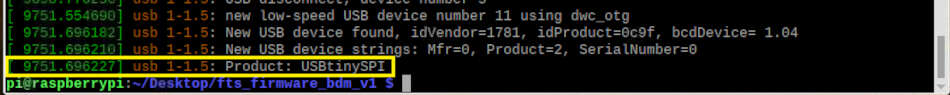
I temporary unplug my board from Arduino and plug into USB. I used USB extention cord. Than I typed lsusb to see the lists of USB devices. It was successful and found my device. I also run the dmesg command. You can see the outputs in a pictures bellow.
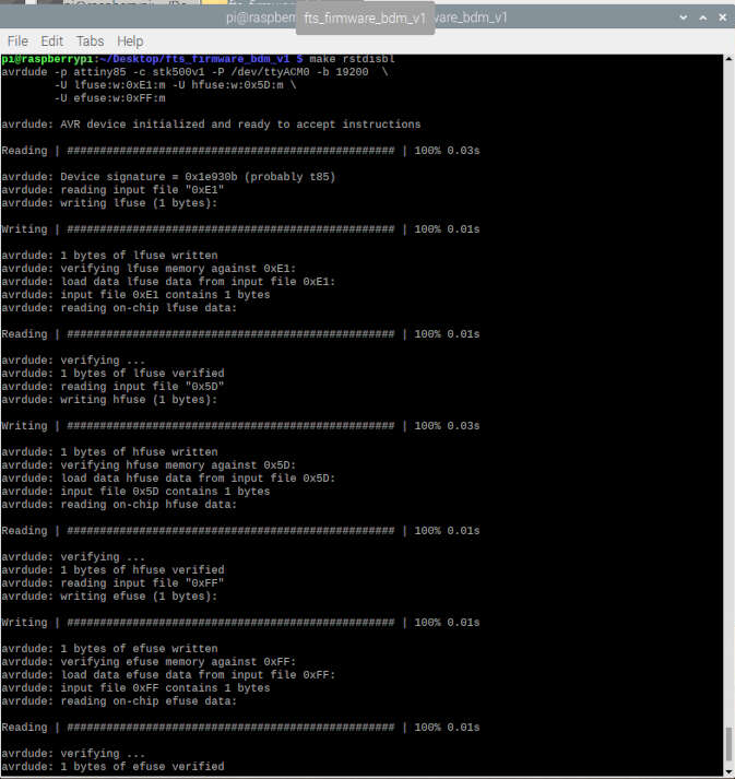
I again connected Arduino Uno to my board one more time, and run make rstdisbl. This does the same thing as the make fuses command, but this time it’s going to include that reset disable bit as well.
One last thing I needed to do is to disconnect VCC from the Vprog pin on the ISP header by removing the bridge on the solder jumper. Now I have a working programmer.
I wanted to try and program my board from electronic design week with fading led. I connected the boards with ISP cable. On my board that I made in electronic design week I needed to supply a power in order to work. I set the 3.3V.
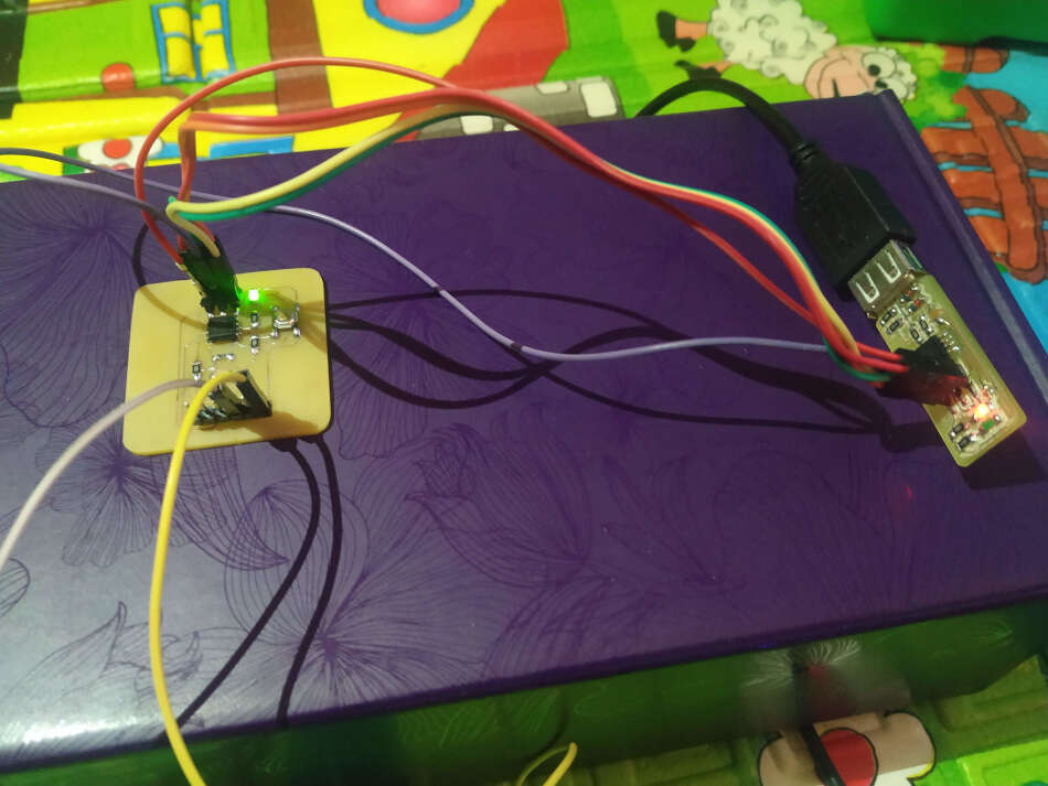
You can see a video of successfully flashed board.
Group Assignment
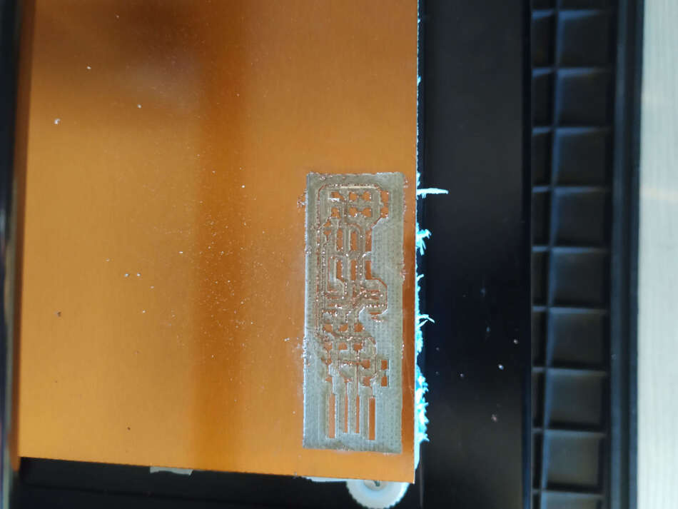
In the group assignment we had to characterize the design rules of our PCB production process. We used linetest png’s to do that.
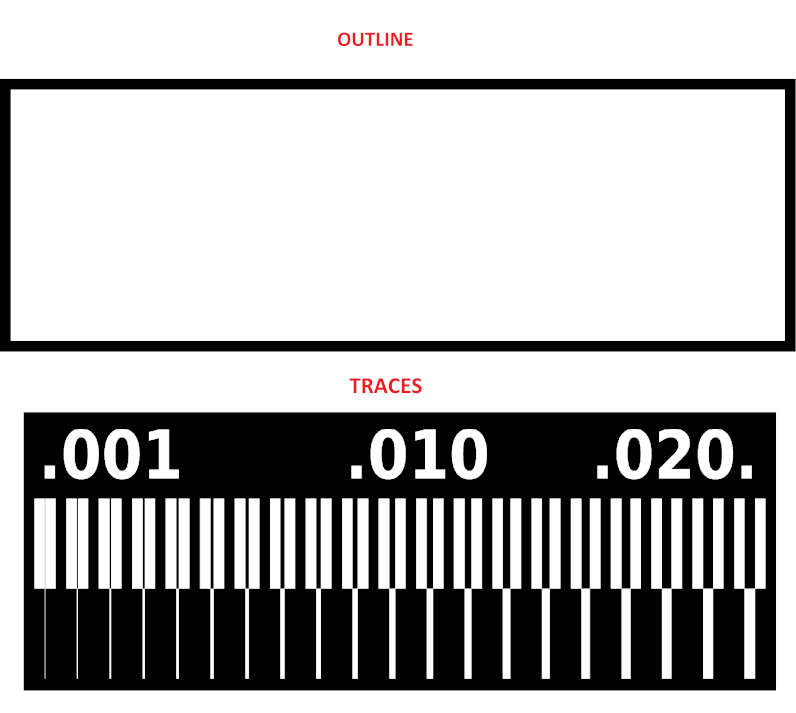
I used modsproject for generating a RML file.
The parameters for traces and outline were the same as for the individual assignment. Only difference that I change is the offset number, I set it to 4.
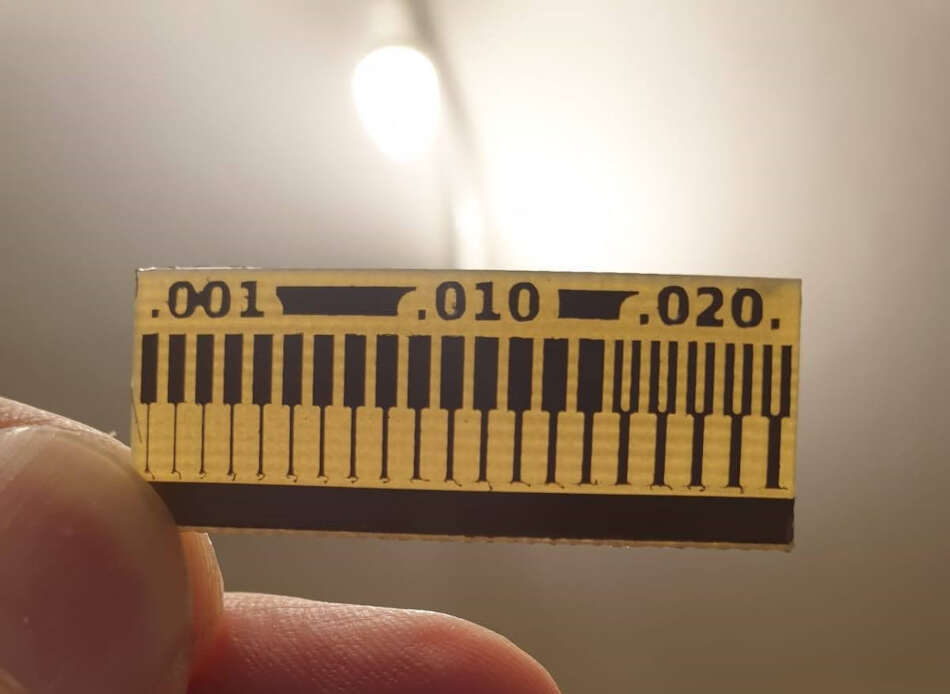
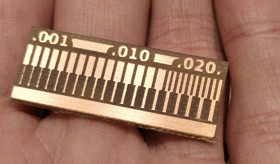
I put the PCB in machine and used DropOut to send RML files to Roland. You can see results in a following pictures.
Another method of making PCB
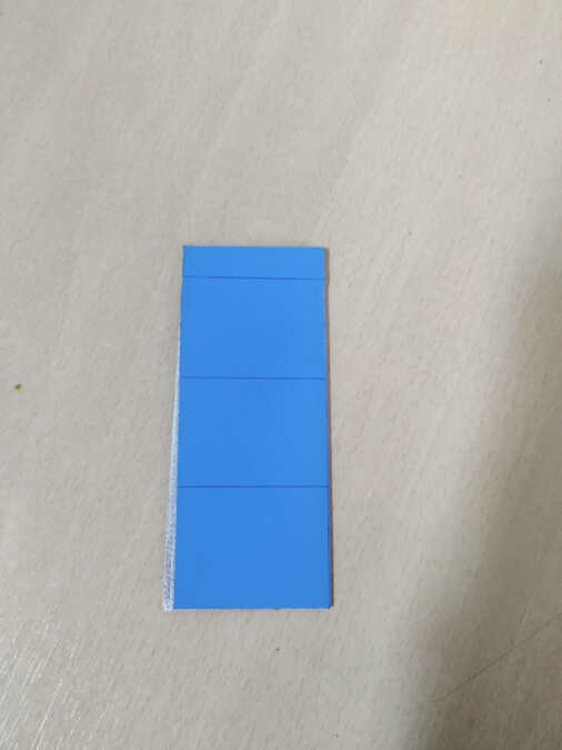
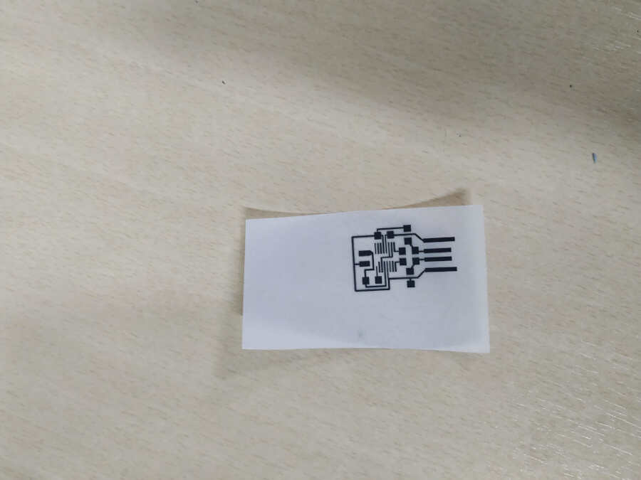
I use Photosensitive pcb for this procedure. There is a protective layer on the pcb that protects it from light. I takes it off. The appearance of the pcb must first be printed on tracing paper.
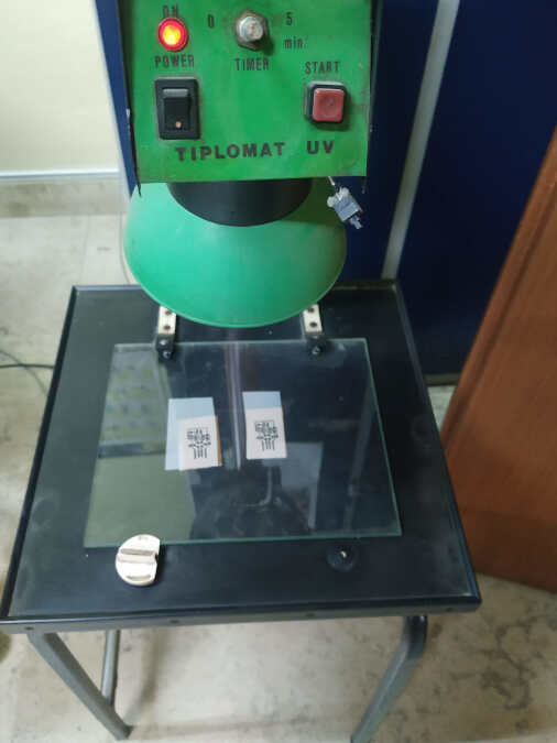
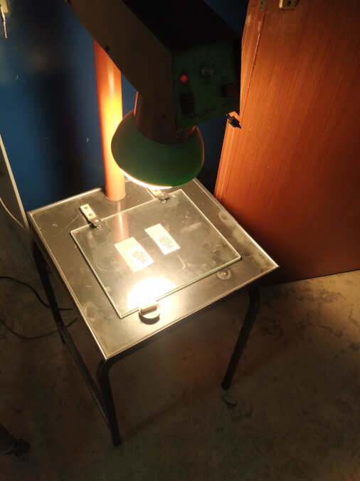
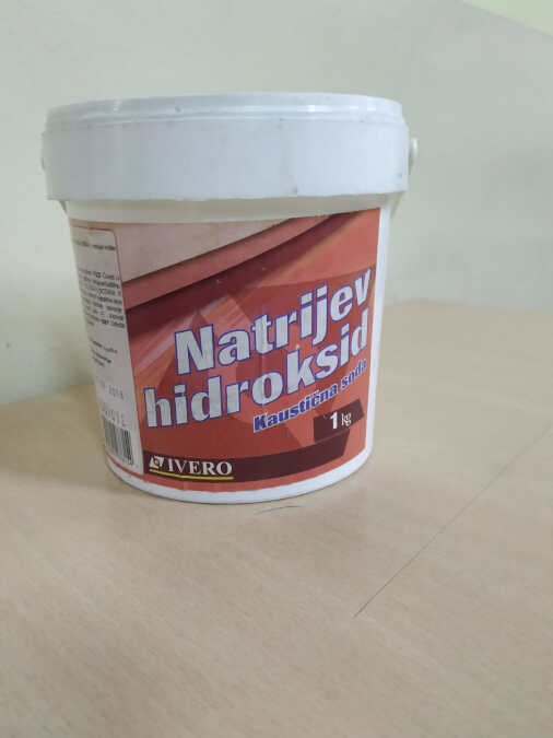
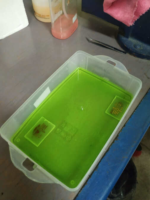
I place the tracing paper on the pcb, cover and place under UV light. The device has a timer that I set to 5 min. After 5 minutes traces are outlined on the pcb surface. The next step is to develop an exposed PCB to see traces better. The developer I use is one teaspoon of sodium hydroxide in ¼ liters of water. It’s not a precise measure.
The developer
Traces can be seen in a few minutes. Then I wash and dry developed PCB.
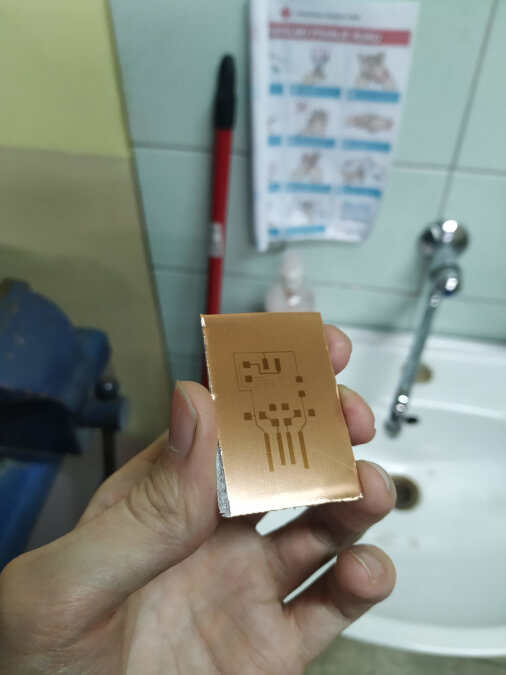
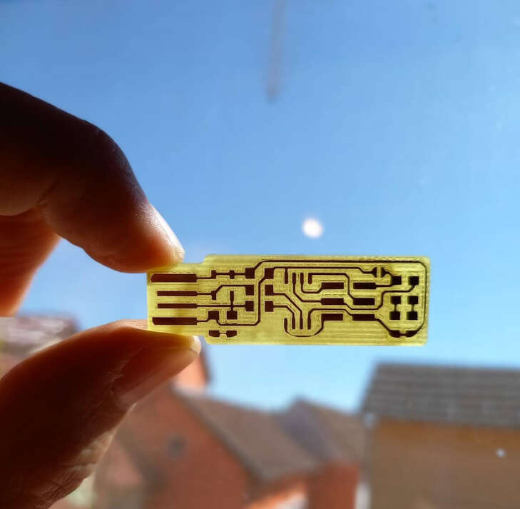
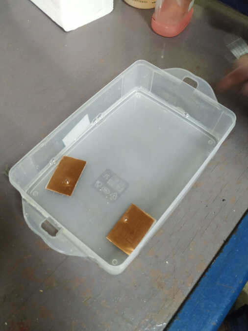
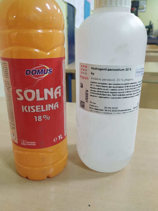
The next step is etching the PCB. For etching I used hydrochloric acid with hydrogen peroxide in a ratio of 2: 1. With gentle stirring after 3 minutes the pcb was removed from the acid and washed with water. Unfortunately the pcb was not fully made successfully because some treces are not visible (especially the part around the IC).
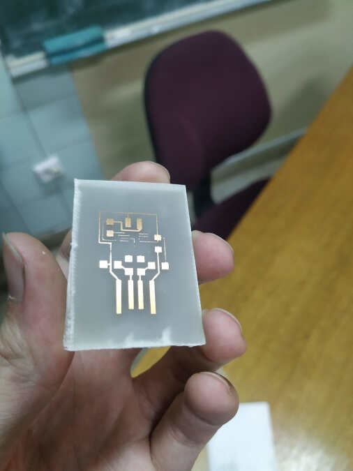
Finally I took the steel wool and sand the surface of the pcb.

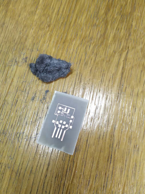
This method is not the best for making PCBs because it works with acids. Acids can be dangerous in contact with skin or eyes. Milling process is definitely better.
Design files:
- Traces_ATtiny85_programmer
- Outline_ATtiny85_programmer
- Group_assignment_traces
- Group_assignment_outline