11. Input devices
Group assignment
Probe an input device’s analog levels and digital signals
So lets start simple with a digital and analog sensor:
Pushbutton

We attached an external button as a first input. Here we attached it to GPIO5 of the ESP. We only had to adjust the button pin in my first test code.
/*
  Based on the ESP8266 Blink by Simon Peter
  Blink the red LED(pin 13), and green LED(pin 12) alternating.
  Build in pushbutton on pin 14on the ESP-01 module
  This example code is in the public domain

*/
int ledGreen = 13;
int ledRed = 12;
int buttonPin = 5;
int buttonState = 0;
void setup() {
  pinMode(ledGreen, OUTPUT);     // Initialize the LED pin as an output
  pinMode(ledRed, OUTPUT);     // Initialize the LED pin as an output
  pinMode(buttonPin, INPUT); //initialize button pin as input
  Serial.begin(9600);
}

// the loop function runs over and over again forever
void loop() {
  digitalWrite(ledGreen, HIGH);   // Turn the LED on (Note that LOW is the voltage level
  digitalWrite(ledRed, LOW);   // Turn the LED on (Note that LOW is the voltage level
  // but actually the LED is on; this is because
  // it is active low on the ESP-01)
  Serial.println("low");
  delay(1000);                      // Wait for a second
 digitalWrite(ledGreen, LOW);  // Turn the LED off by making the voltage HIGH
  digitalWrite(ledRed, HIGH);   // Turn the LED on (Note that LOW is the voltage level
  Serial.println("high");
  delay(500);                      // Wait for two seconds (to demonstrate the active low LED)

  buttonState = digitalRead(buttonPin);

  // check if the pushbutton is pressed. If it is, the buttonState is HIGH:
  if (buttonState == HIGH) {
    // turn LED on:
    digitalWrite(ledRed, LOW);
    Serial.println("btn high");
  } else {
    // turn LED off:
    //digitalWrite(ledGreen, LOW);
      digitalWrite(ledRed, HIGH);
    Serial.println("btn low");
  }
}
This also went well. We also connected a multimeter to measure the on-off state of the button
Potentiometer
Next is an analog sensor, the potentiometer would be one of the simplest to start with The signal or measuring pin of the potentiometer is in the middle. The other ones are connected to VCC and GND


For this we used the analoginoutserial example from the arduino examples. we adjusted the code to have the LED on pin 12 and the potmeter on A0 This code read the sensor, that gives a value between 0 and 1023 and then it maps it to a value for the PWM of the LED, so the potmeter can adjust the brightness of the LED
// These constants won't change. They're used to give names to the pins used:
const int analogInPin = A0;  // Analog input pin that the potentiometer is attached to
const int analogOutPin = 12; // Analog output pin that the LED is attached to

int sensorValue = 0;        // value read from the pot
int outputValue = 0;        // value output to the PWM (analog out)

void setup() {
  // initialize serial communications at 9600 bps:
  Serial.begin(9600);
}

void loop() {
  // read the analog in value:
  sensorValue = analogRead(analogInPin);
  // map it to the range of the analog out:
  outputValue = map(sensorValue, 0, 1023, 0, 255);
  // change the analog out value:
  analogWrite(analogOutPin, outputValue);

  // print the results to the Serial Monitor:
  Serial.print("sensor = ");
  Serial.print(sensorValue);
  Serial.print("\t output = ");
  Serial.println(outputValue);

  // wait 2 milliseconds before the next loop
  delay(2);
}
2. Individual assignment: input on my ESPboard
To do this assignment I designed a new board. The goal of the new board is to use this for both input and output devices, as well as the embedded networking and the interface an application week.
I’ve had too many errors and problems with the attiny-programming. Seeing the results Kurt had with the esp8266 12-E I decided to use the same chip and make a new board.
Again, I drew the schematics in KiCad.
(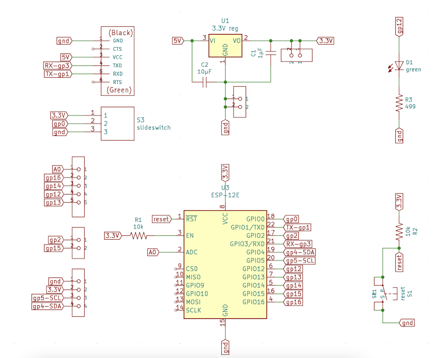 )
)
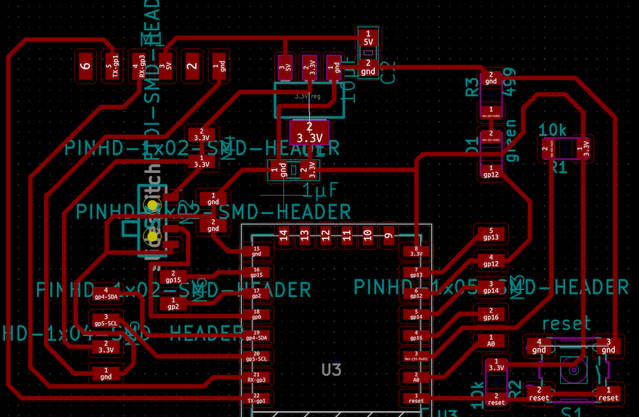
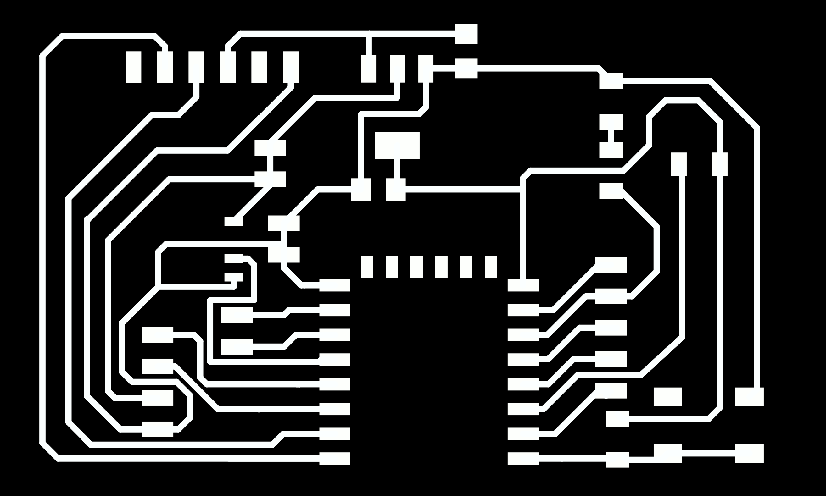
And drew the traces.
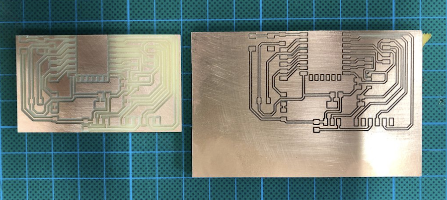
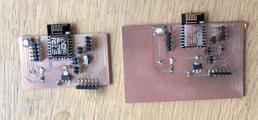
I milled two, one in the lab on the SRM-20 and one on the iModela.
Both were soldered.
With the soldering done, it’s time to start programming.
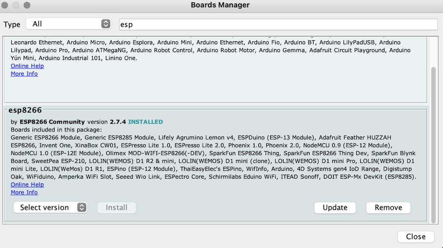
To use the ESP board you need to install an extra library in the preferences. Simply add https://arduino.esp8266.com/stable/package_esp8266com_index.json to the Boards manager URL’s field. Afterwards install the library in the Tools > Board > Boards Manager and look up ESP. The esp8266 is the library you have to install.
Afterwards you need to set the board to “Generic ESP8266 Module”.
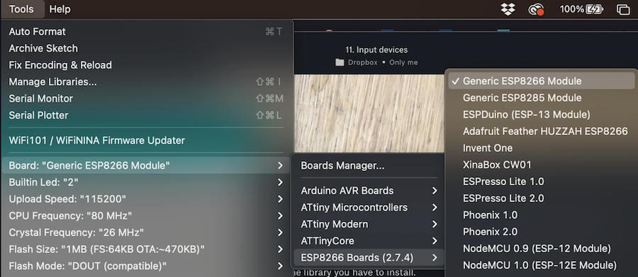
All set!
Input device: Force sensitive resistor
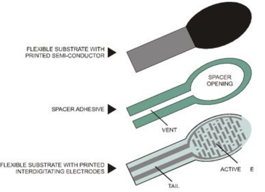
As an input device I used a Force sensitive resistor which I had at home. Because I never used these before, I looked up a manual on how to use them and stubbled upon a great tutorial by Adafruit
The tutorial explains the different layers as well how you should connect and programme it.
You can test the resistor using your mulitmeter and hand. Attach the multimeter to both pins on the FSR, set it in resistor mode and press the sensor. This will allow you to read the resistance in Ohm that the FSR has.
To use this type of input, your board needs to have an analog input sensor. Luckily for me the ESP module has exactly one. Pin 0. You also need to add a resistor between the ground and the pin on the resistor you will use for programming. The other pin is connected to the power.
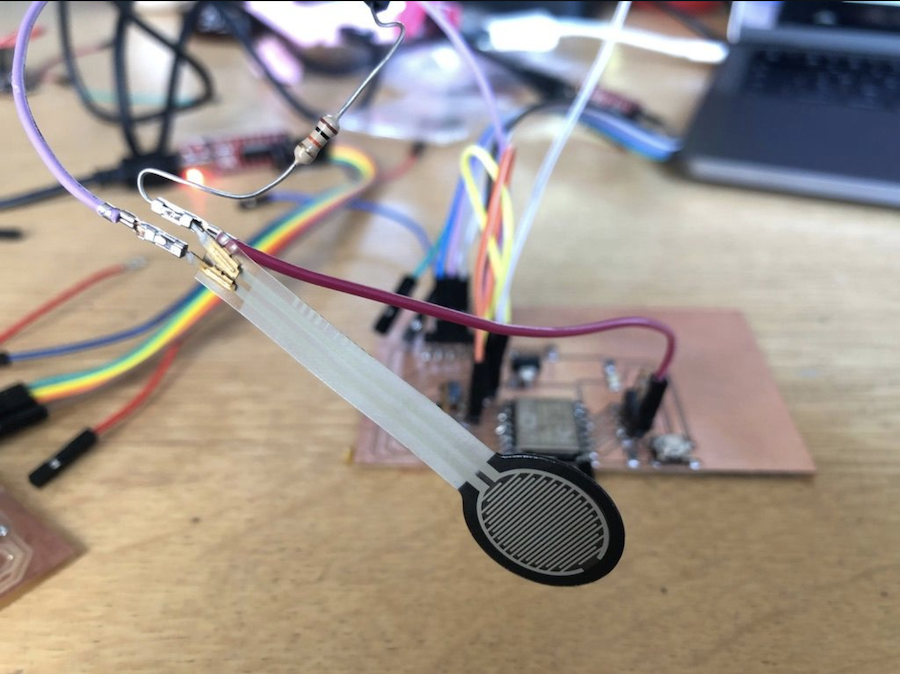
After connecting the FSR to the board, it’s time to upload the code.
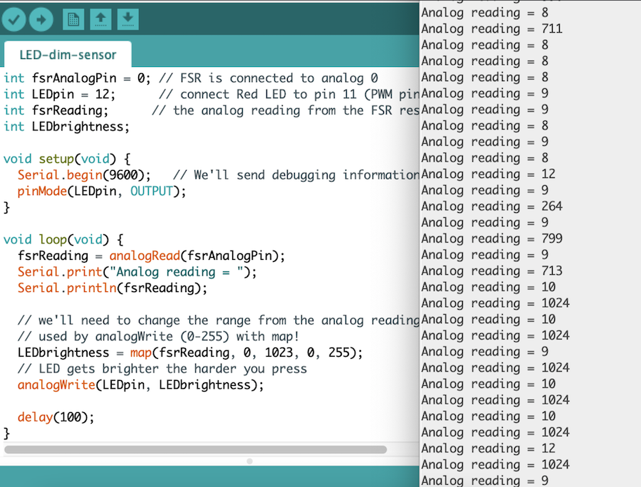
I made a simple piece of code that will allow me to press the SFR and have the led build in on the board go on and off.
/* FSR testing sketch.

int fsrAnalogPin = 0; // FSR is connected to analog 0
int LEDpin = 12;      // connect Red LED to pin 11 (PWM pin)
int fsrReading;      // the analog reading from the FSR resistor divider
int LEDbrightness;

void setup(void) {
  Serial.begin(9600);   // We'll send debugging information via the Serial monitor
  pinMode(LEDpin, OUTPUT);
}

void loop(void) {
  fsrReading = analogRead(fsrAnalogPin);
  Serial.print("Analog reading = ");
  Serial.println(fsrReading);
  LEDbrightness = map(fsrReading, 0, 1023, 0, 255);
  analogWrite(LEDpin, LEDbrightness);

  delay(100);
}
When you look in the serial monitor, you should see values between 0 and 1024. In the code you use, you need to change this value in a value between 0 and 255 for the LED.
The result: