3. Embedded programming and Electronics
CNC Shield
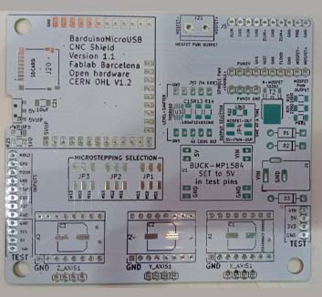
Our robots needs to move and executed some actions based on manual requests. THe displacements will be done by stepper motors. What a better way to do this than to take a CNC project, Fablab Barcelona CNC Shield and adapt it a little bit ?!
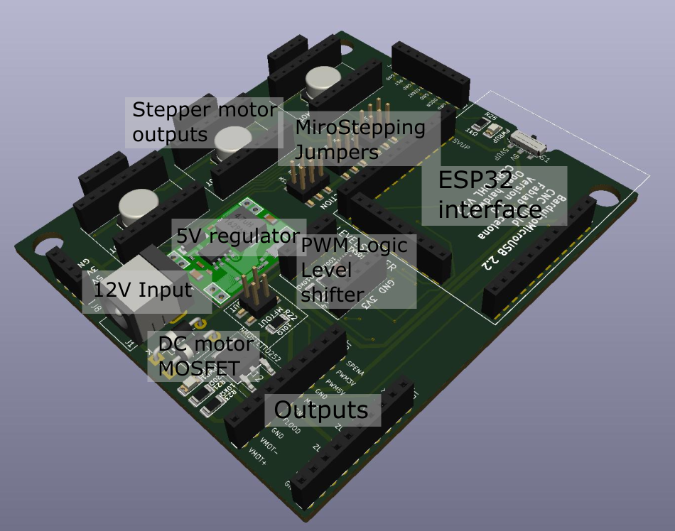
Well this is what we have done. The Fablab Barcelona has created a small portable CNC machine using what they call a CNC shield. It is a 12V, 3 stepper output shield for Barduino that allows micro stepping.
Barduino
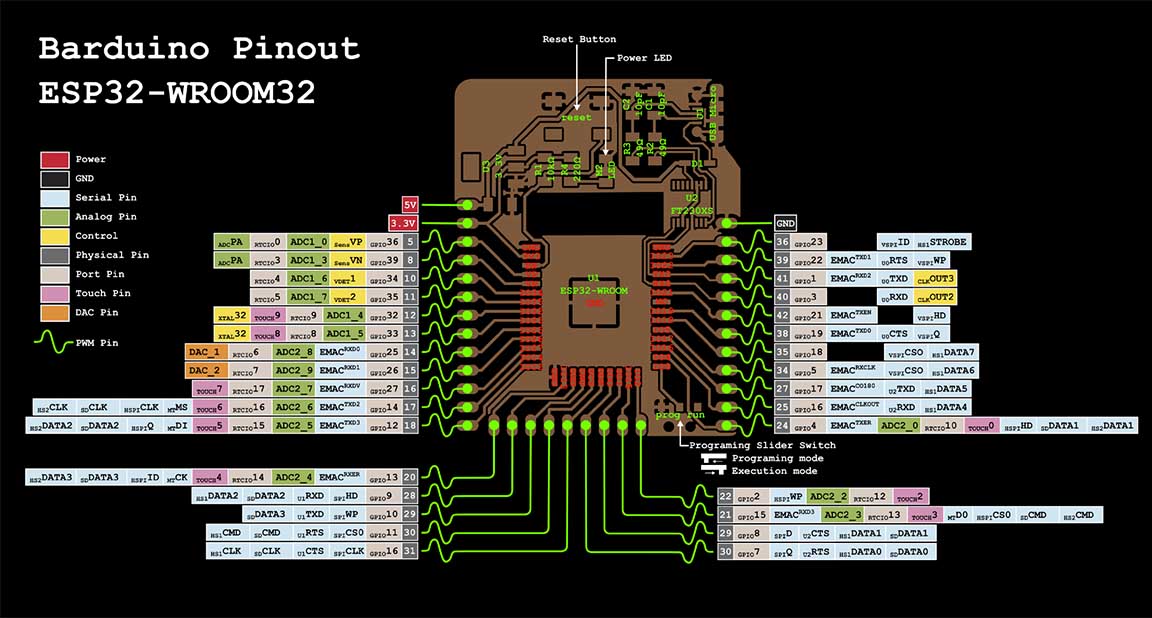
As commented earlier, the CNC-shield is a host board for the Barduino . The Barduino is a project from Fablab Barcelona whose spirit is to make ESP32 accesible on an opensource board. It is powered/communicated via micro usb (no need for FTDI dongle). It allows access to all the pins of the ESP32 and give a 5V or 3.3V output.
This is the board we will program to control our machine. The main reason to use it apart from its numerous output pins and good performance, is its capacity to host a webpage thanks to its wifi module.
Prearing the modules
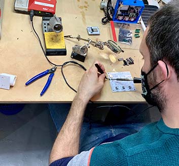
Fabrication
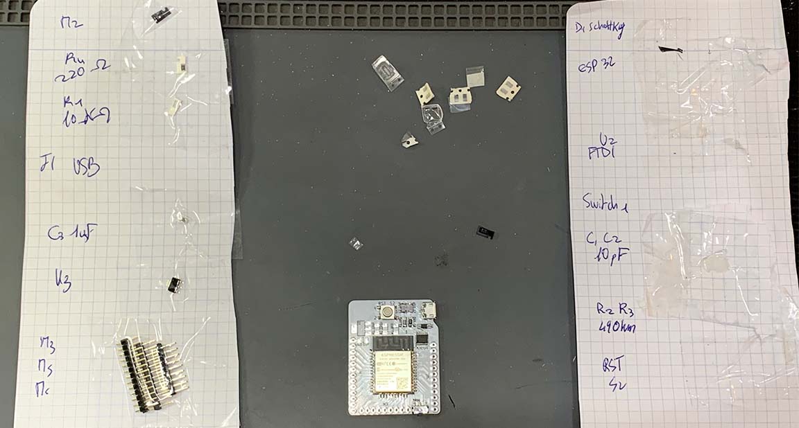
We organized the prepapartion of the module by splitting the work force on the following tasks :
- Preparing the components
- Soldering CNC Shields
- Soldering Barduinos
- Debugging the modules
The teams who prepared the components did a great job to save time for everyone by preparing papers with the components needed, like this only one person ooks for the components instead of waisting the time of 3 persons.
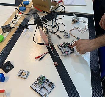
Debugging the electronic
As one can imagine, it was not just about soldering and use it directly. Some kits were not working and we had to debug the following
-
ESP32 not recognized In this case we made a mistake on the voltage regulator which was a 5V instead of 3.3V (they got mixed in the components drawers). On another Barduino it was the TX and RX pins that were not properly soldered.
-
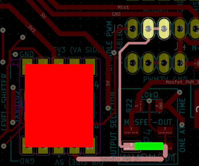
PWM 5V To light-up te led of the button we had no 5V output from the ESP32. The only 5V available was the PWM. But it was not working and I found out it was due to a missing jumper on the board. This is explained below.
On the page of group2 one can find the work we have done to set up the stepper driver thanks to Carla’s explanation and tutorial she gave us.
Embedded programmation
Now that we have our two modules ready and we got to know them we can start using them.
GRBL32 - GCODE
FabLimb - Webserver and direct control
After seeing that G-CODE based firmware was not fully adapted to the instant reaction need we have for our game, our instructors told us about a project call FABLIMPLEO which consits in streering a dirigible using an ESP8622 board and a webpage. One can see the project here.
The base project was made for ESP8622 and for a 3D movement machine. The project comes in two version, Wifi Hotspot or Wifi Server.
- Wifi hotspot : the ESP create a wifi hotspot to which the users connects itself using mobile phone or computer.
- Wifi server : the ESP and the users’s mobile phone have to be connected to the same network.
We preferred the Wifi Hotspot version not to be dependent on a working wifi network and to avoid reflashing the ESP everytime the wifi password or SSID changes.
Adaptation for our AwesomeMachine
The FabLimp project and our project being slightly different we had to proceed to several adaptation and choices to fit with the teams requirements.
The main tasks we had to do to use the Fablimp project were : - update the library to EP32 - adapt the PIN definition - change the actions
Once this was done, we encountered several issues with the control and we modified the structure of the code.
Once the control was fitting our needs we had to modify further the code to allow for the detection of the button being pushed and the LED animation.
Adapting to ESP32 and Awesomemachine
Libraries : the table below presents the library update we did
| Library | ESP8622 | ESP32 |
|---|---|---|
| Wifi | ESP8266WiFi.h | WiFi.h |
| WIfi Client | WiFiClient.h | WiFiClientSecure.h + ssl_client.h |
| WebServer | ESP8266WebServer.h | WebServer.h |
| DNS | ESP8266mDNS.h | ESPmDNS.h |
To find them we used some Web research at first and also used extensively the great examples that come within Arduino framework.
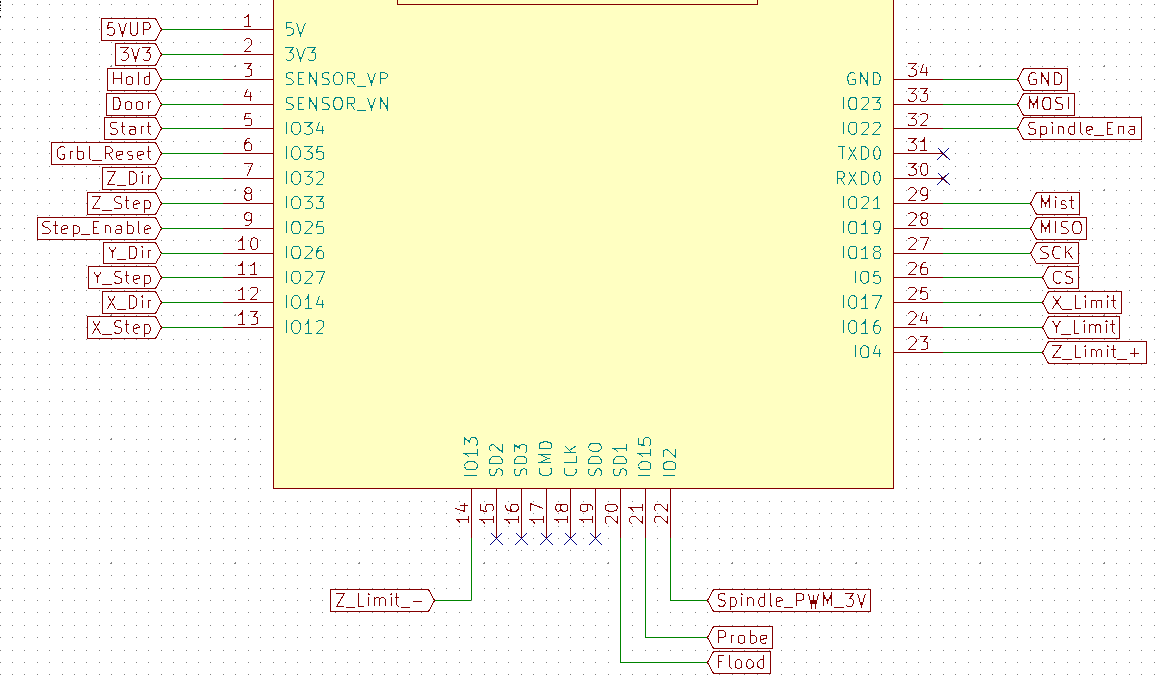
PIN definition
On the picture below one can see the pin definition we are using for our project.
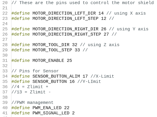
We made it based on the Schematic file available in the barduino-cnc-shield repo

Motors
Indeed we can see that for each axis (X,Y, Z) somes pins were predefined
to run the STEP and the DIR commands. As we are going to need them to command
our motors we add them to our code. We used a name as explicit as possible
so that someone reading the code afterward can easily understand what
we are doing. The pin 25 is used to enable motors, it is important to know
what you will do with your motors because once this pin is unset the
motors cannot withstand any load.
Button/LED
As explained in the project goal, the winning team is the one who will push
the button of the other machine. We chose to use a set of LED+button and wired
it as follows.
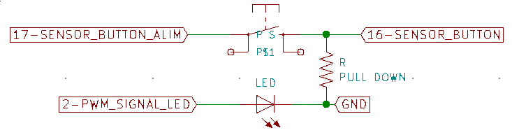
The button sees a logical 3.3V voltage on its input coming from pin GPIO17.
Its output is connected to the pin GPIO16. We will then monitor GPIO16 to know
if the button is pressed or not.
Also a pull-down resistor is installed between GPIO16 and GND to avoid leaving
the GPIO16 in qn undetermined state that can be affected by any electromagnetic
perturbation.
The ESP32 has no 5V output as required to power-up the LED. But the CNC shield has a PWM level shifter that allows to increase the voltage of the ESP32 PWM control which is at 3V. We then connect the LED to the PWM 5V of the CNC shield and control it through PIN2.
At first even if the PWM 3.3V was working fine we had no 5V PWM. Looking at the PCB file of the CNCshield we found out that a jumper was missing on our board.
How the code/web interaction works
To control our machine we are using two scripts :
- INO file
- H file
The INO file contains the code that runs the machine and receive orders from a web page. The web page is contained in the H file.
As an example, to move left the user will push the button “left” of the application. In the HTML the left button is created as follows
<!-- ButtonLEFT -->
<div class="column">
    <button id="left" type="button" class="button" style="height: 100%; width: 100%" onmousedown='makeAjaxCall("left")' onmouseup='makeAjaxCall("driveStop")' ontouchstart='makeAjaxCall("left")' ontouchend='makeAjaxCall("driveStop")'>LEFT</button>
</div>
For this button we can see 4 possible interaction
- onmousedown
- onmouseup
- ontouchstart
- ontouchend
Each action calls an Ajax function that has to be tuned depending on how one wants the machine to react. In this case we have two different actions.
- left : that will trigger a left turn
- drivestop : that will stop the machine
Both this action can now be checked in the INO code to see what exactly happens
Several actions are set-up in this code to handle a request from the webpage.
- First we detect a left action sent by the HTML and set tha variable ‘action=”left”.
- In the ‘loop’ an if statement with the ‘action == left’ check allows to enter into a specific code.
- Here we change some pin status and one can see that we actuate on the right motor to go left. For the right motor we set up the DIR pin to LOW to choose a direction and then we set up the coil action by set the STEP to HIGH. A millis loop allows us to wait a bit and then set the STEP to LOW. The time during the while loop is used to define the speed.
1 2 3 4 5 6 7 8 9 10 11 12 13 14 15 16 17 18 19 20 21 22 23 24 | |
The actionstop if only defined in the setup loop. In this case we define
the action to “STOP”. In this way, when running the loop function,
no moving action is detected.
In the code presented below I show the 3 kind of stops we use. For the moment
they have the same effect, but having separate case gives more flexibility
when it comes to fine tune the machine behavior.
1 2 3 4 5 6 7 8 9 10 11 12 13 14 15 16 | |
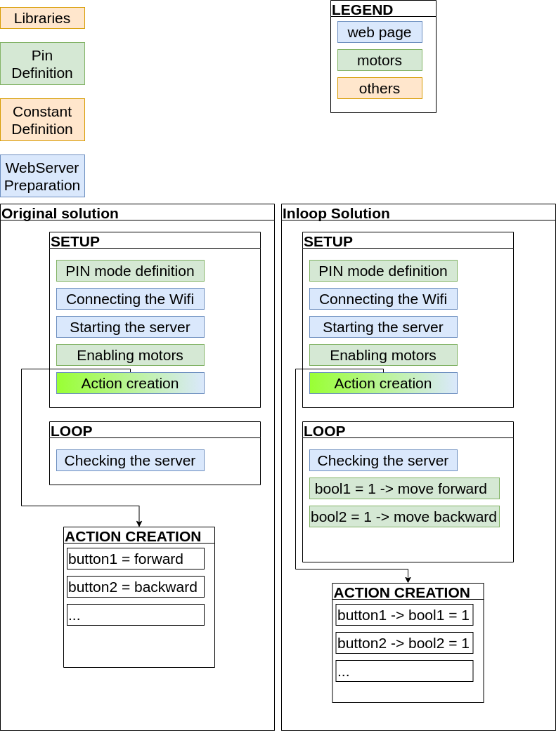
Adaptation
Already talked in detail how the script works. The version presented above is an adaptation of the base version. Indeed the original code was meant for DC motor that only needed to receive constant voltage to work. In our case we have to send to the motor the “raw” stepping command as explained here (LINK TO STEPPER MOTOR THEORY) as long as we want the motor to move.
We first tried to put delays in the ‘server.on’ commands to run the loop for sometime. But the action would never stop because the delay in this part of the code would prevent the other requests from the webpage to reach the INO code.
To correct this behavior, we changed the roles a little bit :
- server.on : used to set-up the ‘action’ variable to the desired action (left, right, front…)
- if statement in the loop : here we do the actual motor movement
Advantages : it works as desired
Disadvantage : the engine speed will be limited by the size of the loop
Controlling the steppers
1. Understanding Stepper Motors
a. Brushless DC Motors
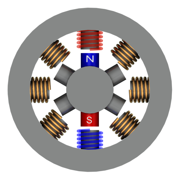
Stepper motors are essentially brushless DC motors (bDC). At the core of a bDC motor is a polarised magnet, known as the rotor, surrounded by windings/coils, acting as electromagnets, and also reffered to as the stator.
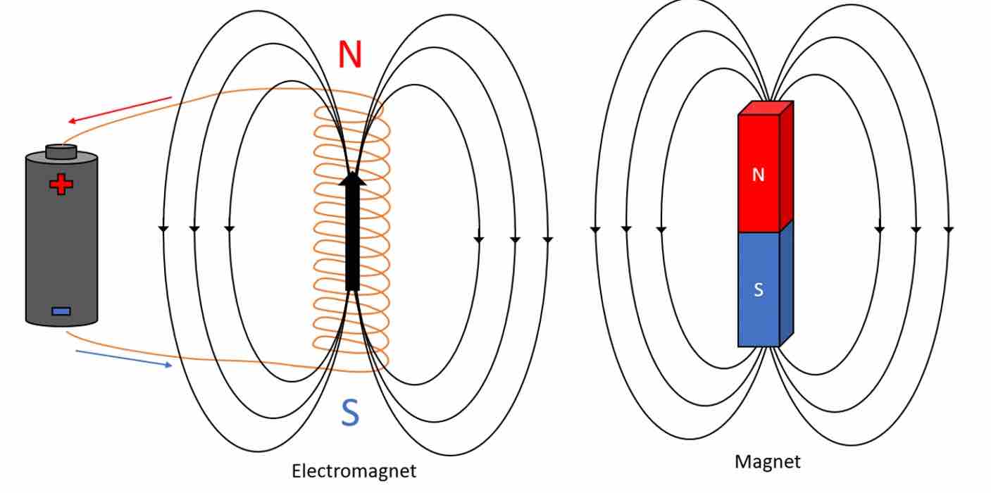
Electromagnet (Left) and Magnet (Right)The stator, as opposed to rotor, is the static element of a motor that actively participates in the production of the output movement. Let us assume the rotor magnet is surrounded by three electromagnets as shown in the below GIF.
Feeding current to a coil in a particular direction generates an electromagnetic field whose poles can be inverted by feeding current in the opposite direction. By feeding current to two coils in opposing directions and opposing sides of the magnet induces the rotor into motion as it attempts to align its poles with those of the electromagnets.
Sequenced Activation of Coils generating a rotary motion of the rotor in a brushless DC motorIn essence, the controllability of bDC motors is limited as it is not possible to know with exact certainty in what position the rotor is. Rotational speed can be manipulated, allowing for estimations to be made. However, this process is not ideal for precise endeavors.
b. Stepper bDC Motors
In contrast to pure bDC motors, stepper motors do allow for position control. This is because of its multi-pole rotor. In short, each magnet, or pole combination, constitutes a specific position. By activating the corresponding electromagnets, the rotor can be moved position by position. While this reduces the resolution by which the rotor moves and thus the “smoothness” of the rotary motion, it offers great positional control and ease of use, as detailed in section 2.
Stepper Motor2. Controlling Stepper motors
The Barcelona lab had a few NEMA standardised stepper motors whose characteristics are listed in the below table. The power train was designed around these.
Motor Characteristics (As listed on Datasheets)
| Motor | Steps(Resolution) | Phases | Dimensions | Holding Torque | Rated Voltage | Current | Operating Temperature | Quantity |
|---|---|---|---|---|---|---|---|---|
| NEMA11 | 200(1.8 degrees) | 4 | 36 mm | 9.1 N.cm | 12V DC | 1.8A @ 4V | -10 to 40 °C | 4 |
| NEMA17 | 200(1.8 degrees) | 4 | 33 mm | 42. N.cm | 12V DC | 1.8A @ 4V | -10 to 40 °C - | 5 |
a. Drivers
The control of our motors requires the generation of a square wave whose frequency is defined by the amount of time the program allows before it changes the state of the signal it outputs. The sample time (time it takes for the wave’s pattern to repeat itself) defines the rotational speed at which the motor operates.

Square WaveController circuits run on low current signals, yet motors need high current signals to operate. Motor drivers are interfaces used to convert low current control signals to high current ones.
b. Arduino Code
Test Code
/*Example sketch to control a stepper motor with A4988 stepper motor driver and Arduino without a library. More info: https://www.makerguides.com */

// Define stepper motor connections and steps per revolution:
#define dirPin 32
#define stepPin 33
#define Motor_Enable 25
#define stepsPerRevolution 200

void setup() {
  // Declare pins as output:
  pinMode(stepPin, OUTPUT);
  pinMode(dirPin, OUTPUT);
  pinMode(Motor_Enable, OUTPUT);
  digitalWrite(dirPin, HIGH);
  digitalWrite(Motor_Enable, LOW);
}

void loop() {
  // Set the spinning direction clockwise:

    digitalWrite(stepPin, HIGH);
    delay(500);
    digitalWrite(stepPin, LOW);
    delay(500);
}
c. Effect of delays
The Arduino abstraction features four seperate commands used to introduce time-based functions. These are defined below.
| Command | Description |
|---|---|
| delay() | Pauses the program for the amount of time (in milliseconds) specified as parameter. (There are 1000 milliseconds in a second.) |
| delayMicroseconds() | Pauses the program for the amount of time (in microseconds) specified by the parameter. There are a thousand microseconds in a millisecond and a million microseconds in a second. |
| millis() | Returns the number of milliseconds passed since the Arduino board began running the current program. This number will overflow (go back to zero), after approximately 50 days. |
| micros() | Returns the number of microseconds since the Arduino board began running the current program. This number will overflow (go back to zero), after approximately 70 minutes. |
As described above, using delay functions pauses the whole program for the defined amount of time. As such detection of inputs will be halted until that amount of time has elapsed, thus preventing control over the system. On the other hand, millis()/micros() returns the amount of time elapsed since the board began running. This value is computed internally, and, depending on how the program is written, can allow for time considerations to be implemented without causing an interruption.
Following the tutorials found in link 3.2, We first came up with the following solution:
digitalWrite(MOTOR_DIR, LOW);
digitalWrite(MOTOR_STEP, HIGH);
currenttime = millis();

while(millis()-currenttime < 0.1){
}

digitalWrite(MOTOR_STEP, LOW);
currenttime = millis();

while(millis()-currenttime < 0.1){
}
Here, a while loop is used to create a time interval between changes in motor state. However, In this sequence, the while loop acts basically as a delay function would. We therefore modified it to the below. The new structure functions around an if loop. If the desired time has elapsed then the state of the motor is changed and the values keeping track of the elapsed time are reset. This means that changes only occur when the specified threshold is met without pausing the program. This is the logic we implemented in our program
if(millis() - currentTime >= 0.1){
  motorState = !motorState;
  digitalWrite(stepPin, motorState);
  currentTime = millis();
}
Controlling the LED/Button
The control of the LED and “Match winning Button” is a bit different because it does not go through the web application. As explained above we are using a PWM output at 100% to provide a 5V output to the LED. So if a pression on the button is detected digitalRead(SENSOR_BUTTON) == HIGH we create a blink of the LED for 10s during which the robot cannot move ( it is bloqued in the while loop on purpose).
// ==SENSOR
  if((digitalRead(SENSOR_BUTTON) == HIGH) && (boolKill == 0)){
    boolKill = 1;
    currenttime = millis();
    while(millis()-currenttime < 10000){
      ledcWrite(0,0);
      currenttime_blink = millis();
      while(millis()-currenttime_blink < 500){
      }
     ledcWrite(0,254);
      currenttime_blink = millis();
      while(millis()-currenttime_blink < 500){
      }

    }
    boolKill =0;
  }