Our Tool
Concept
Our group decided to design a tool similar to a mine flail. Mine flails consists of balls hanging on heavy chains attached to a horizontal, rapidly rotating rotor, mounted on two arms in front of a vehicle. They were used during world war 2 to clear paths from mines by deliberately triggering them.

Mine Flail on a Sherman TankWe started with a concept drawing describing the structure of the tool and its different components.
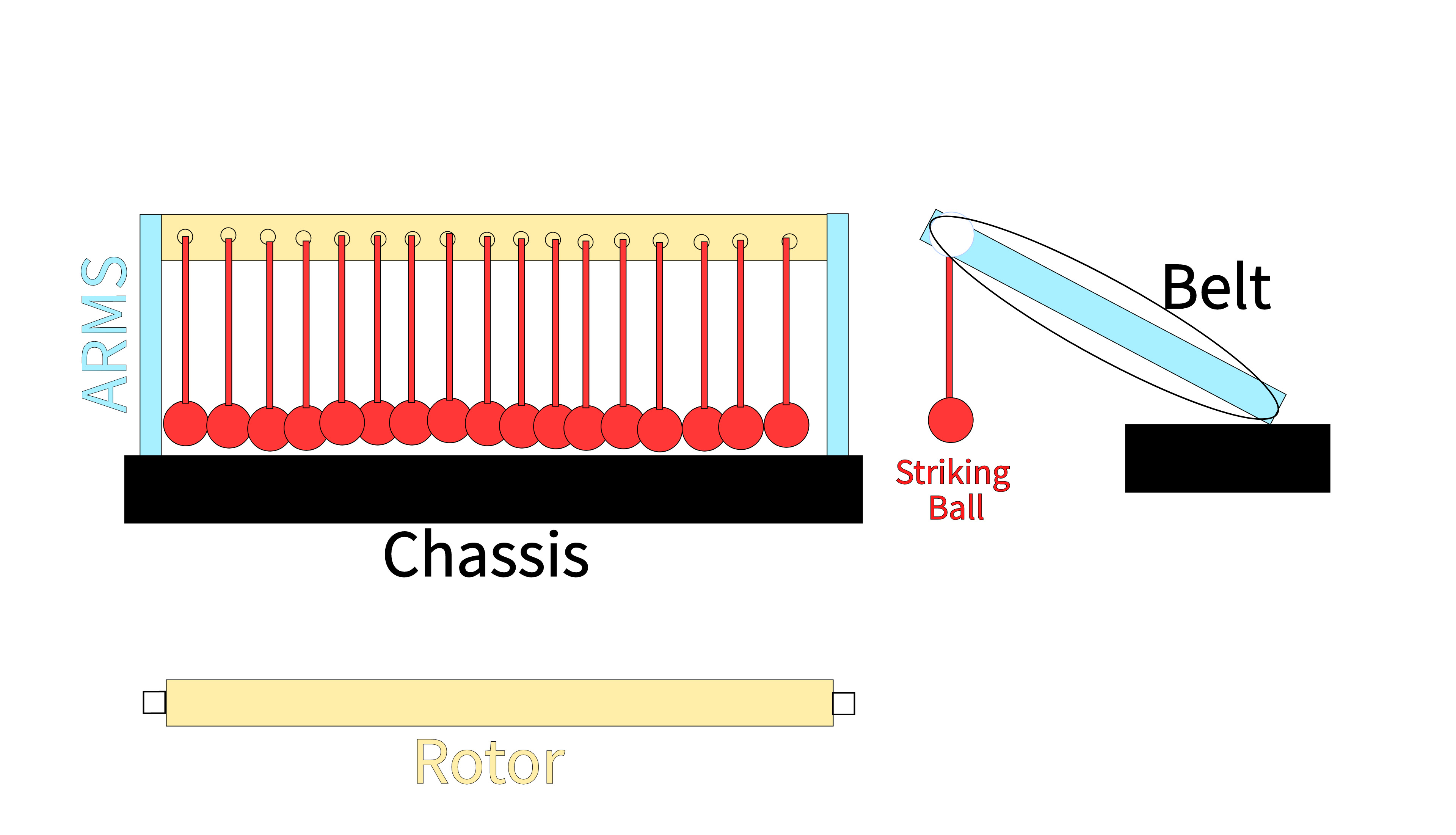
Flail Tool Concept SketchOur tool functions exactly like a mine flail. However, instead of triggering mines, the hanging elements are used to strike the target button. A motor installed on the chassis drives a belt attached to the rotor, driving its rotation.
We split the design of all components in three. Adrian took care of the arms, Lynn of the striking balls, and Tarek designed the rotor.
Tool Design
So technically, to make it work, we had created the following design.
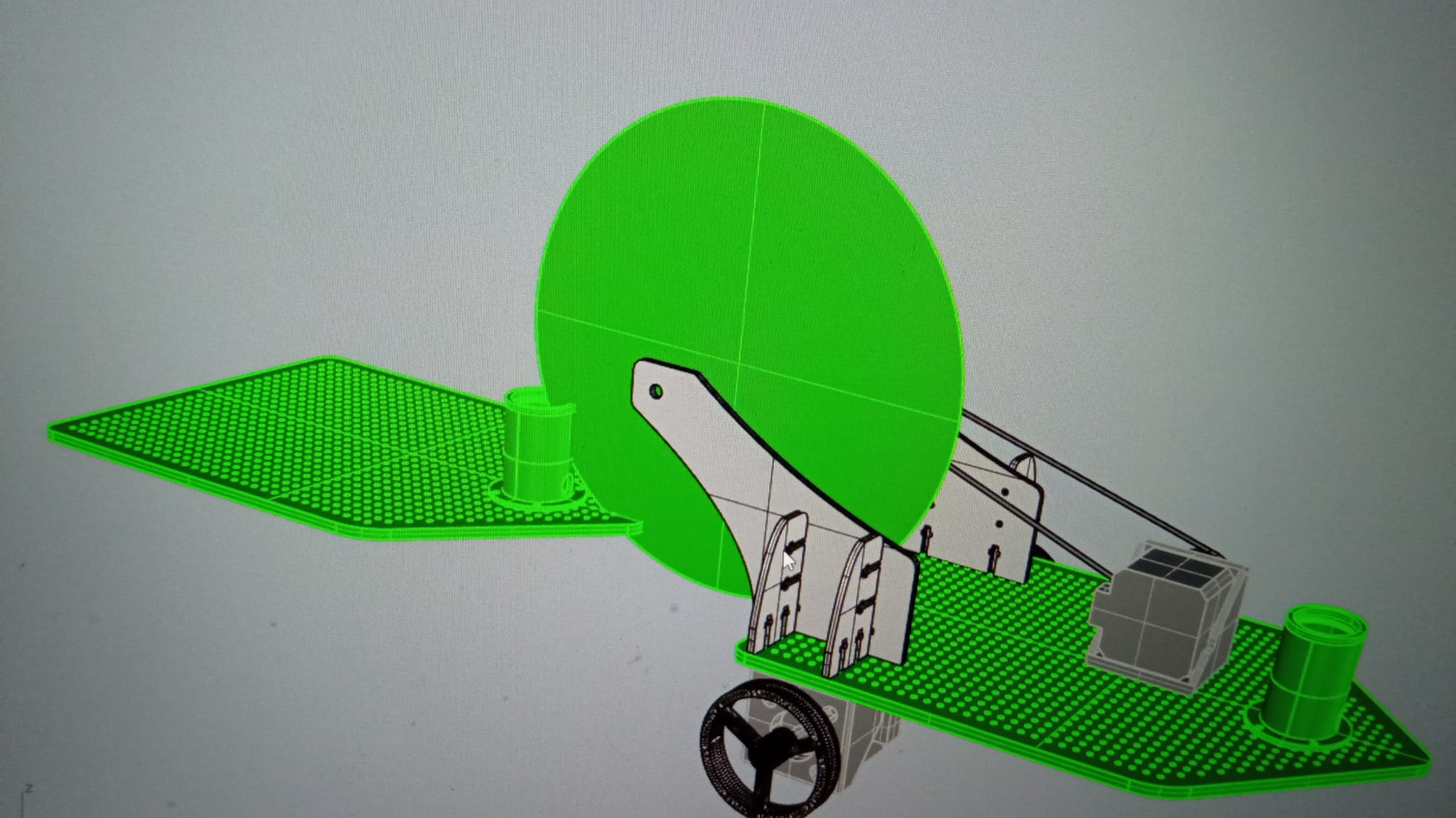
The idea is to make this move with the generator Z.
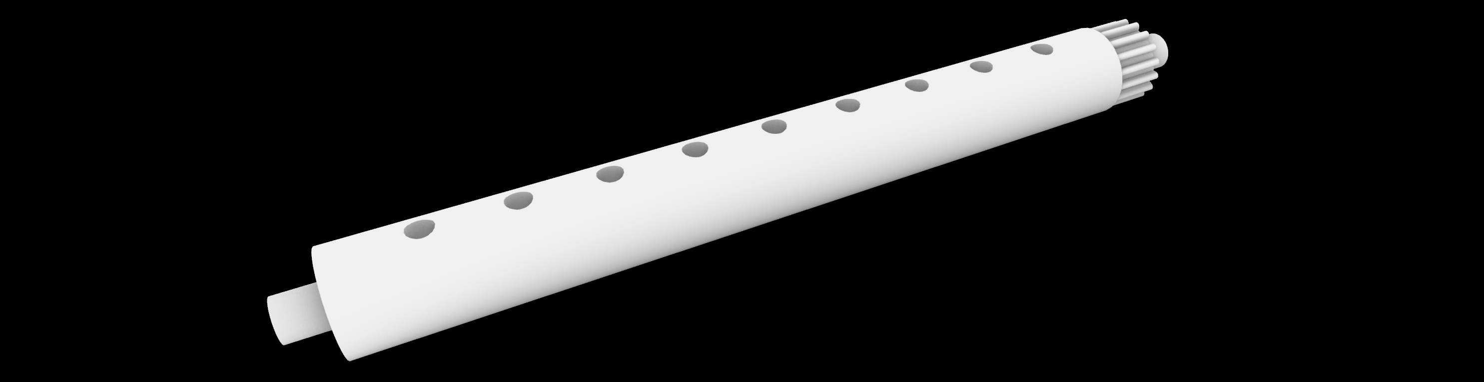
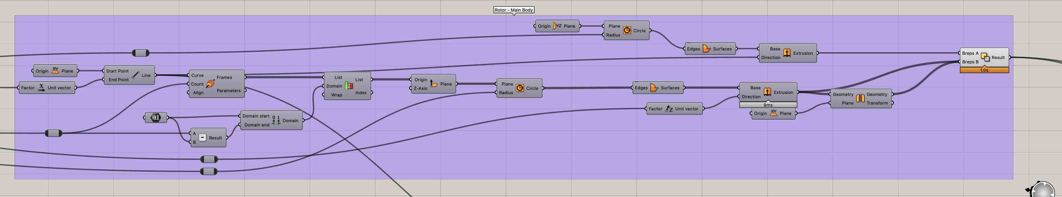
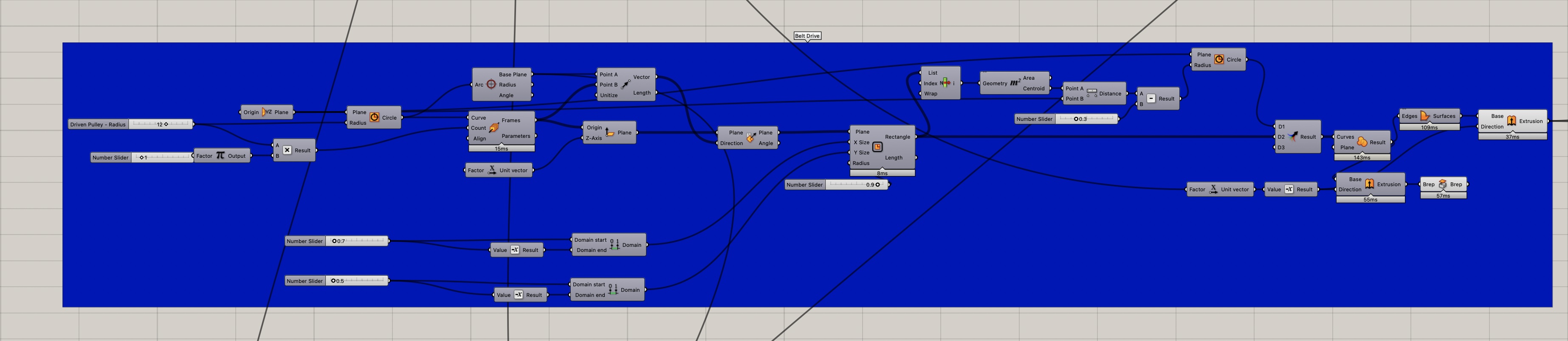
Rotor Concept SketchThe main rotor was designed on grasshopper, allowing for dimensions to be adjusted on the fly. Its main body was composed of two areas. One shaped as a pulley to be connected to the belt. The other contained through holes spread along its length. These holes would allow for striking elements to be attached to the rod with threads. Furthermore, a driver pulley was designed and attached to the head of the motor. This pulley was designed to give an overdrive with a ratio of 3:1. This was done to allow the rod to rotate sufficiently fast to generate a significant striking force.

Tool fabrication
In order to create the tool, we had done the following:
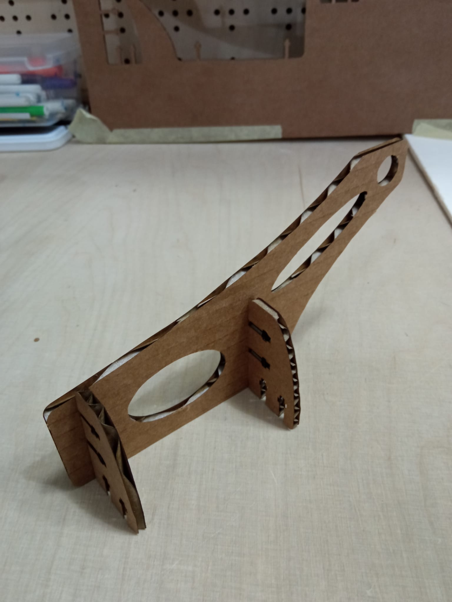
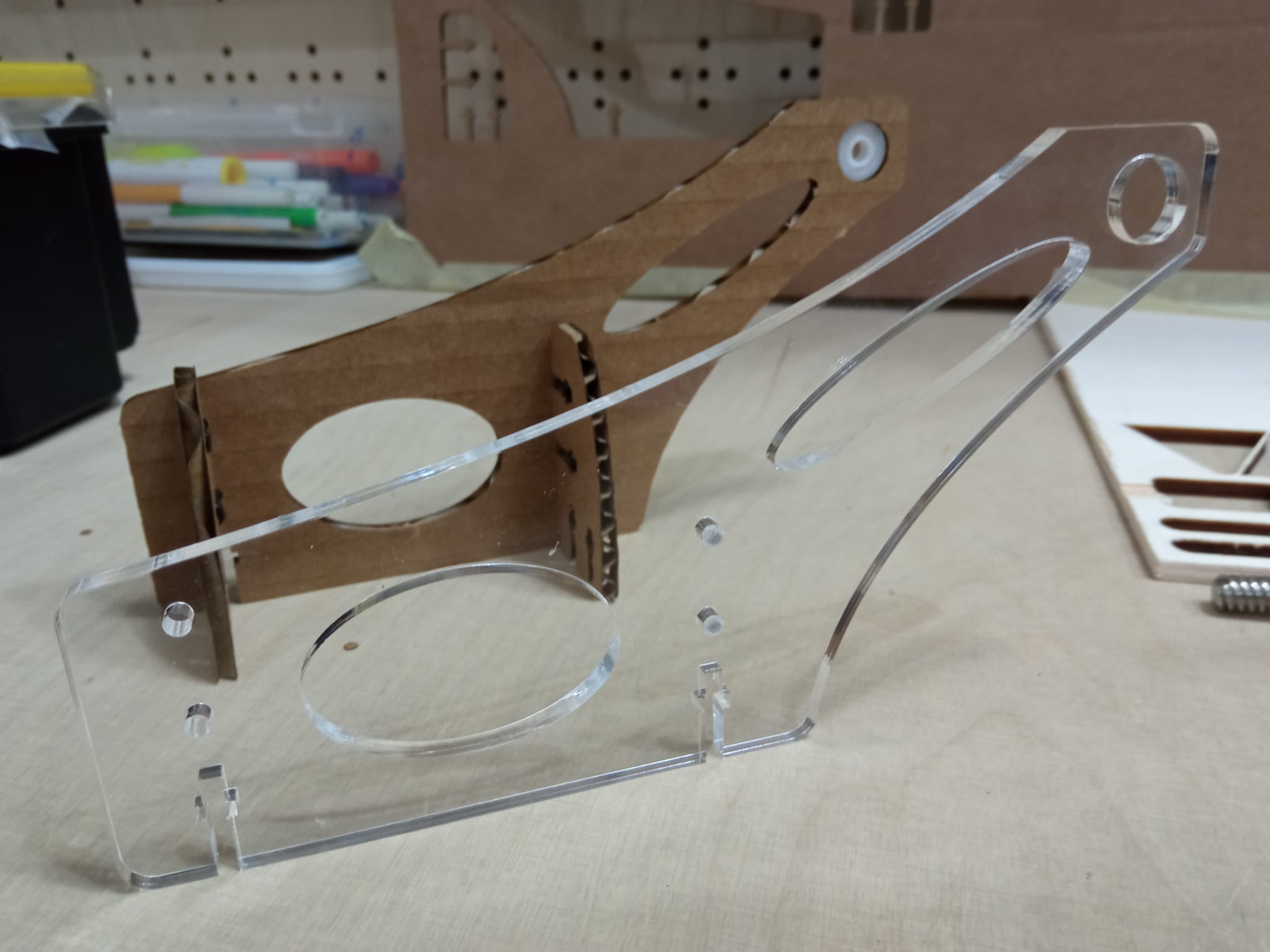
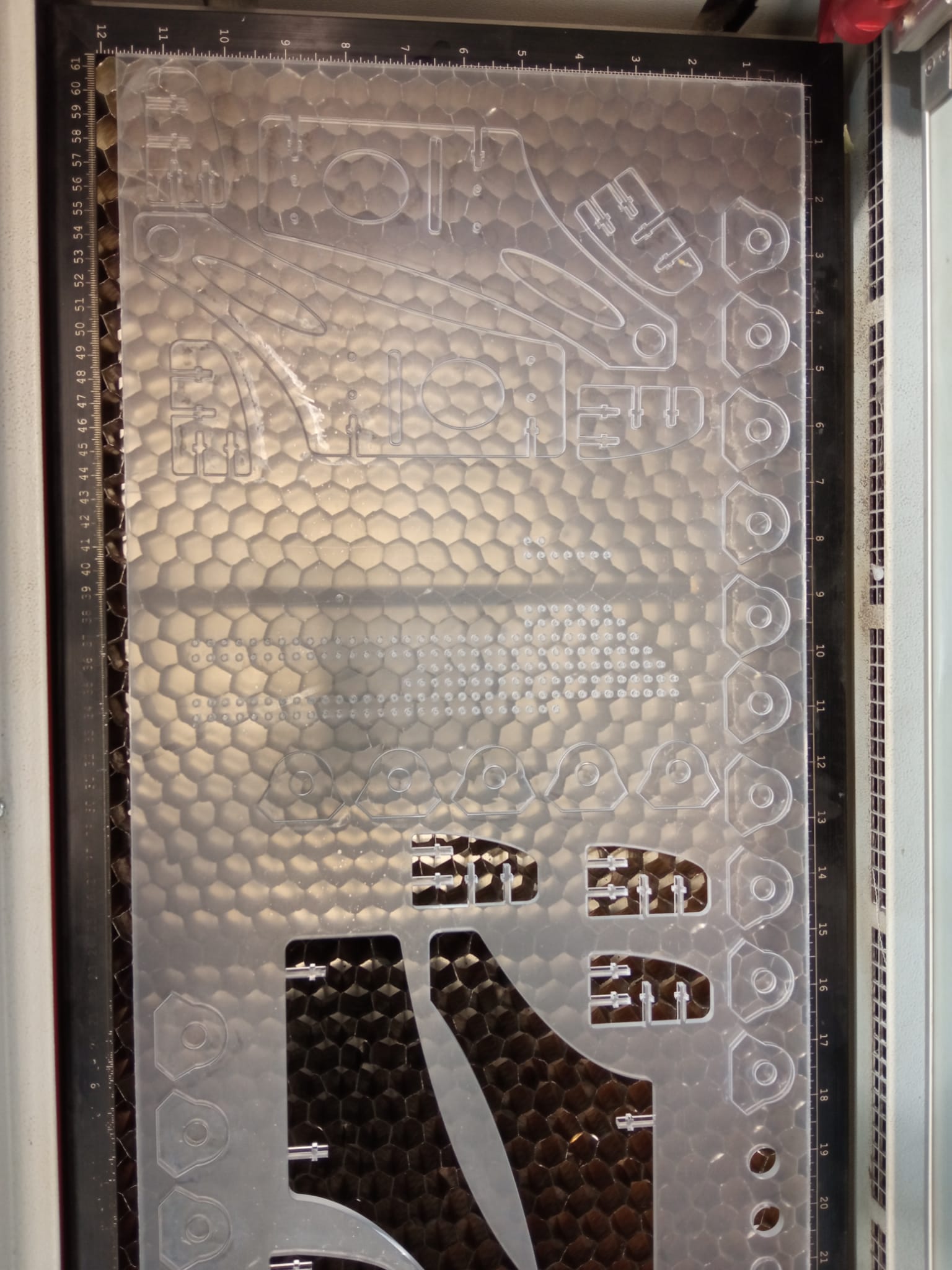
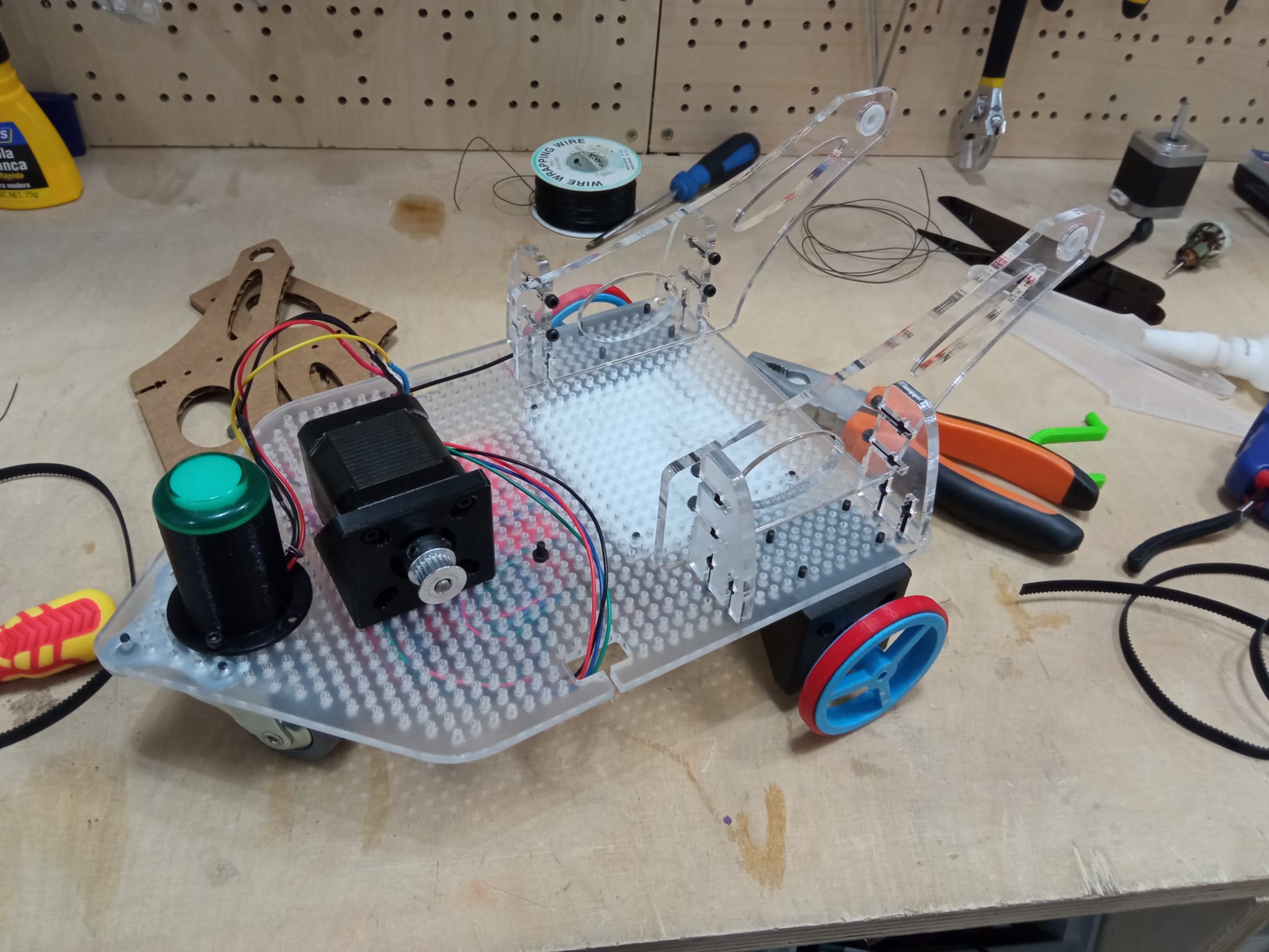
1. laser-cut the support for the tool axis.
We had keep in mind that the distance base-toolaxis is equal to tool-button of opponent.
-
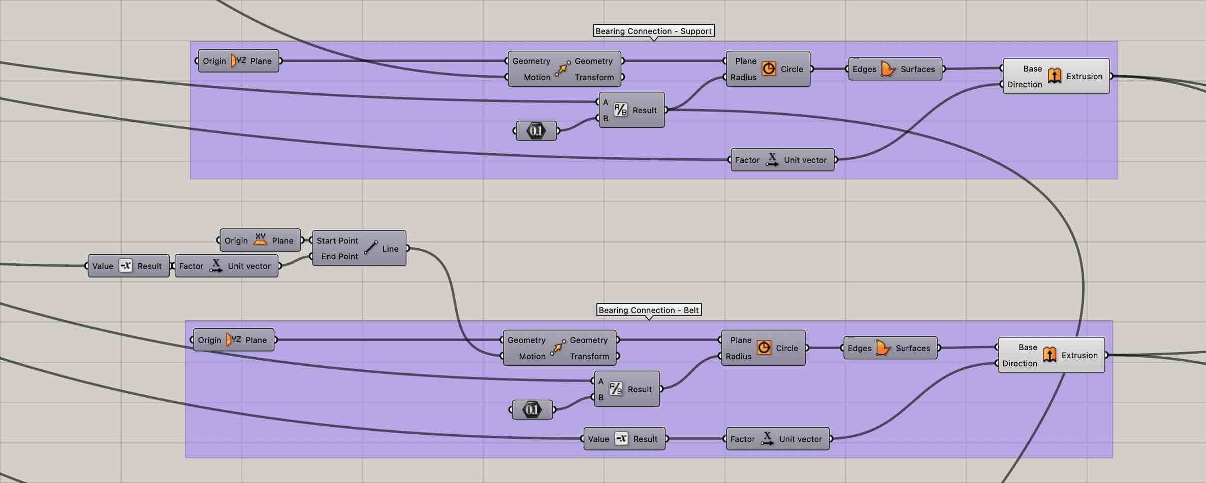
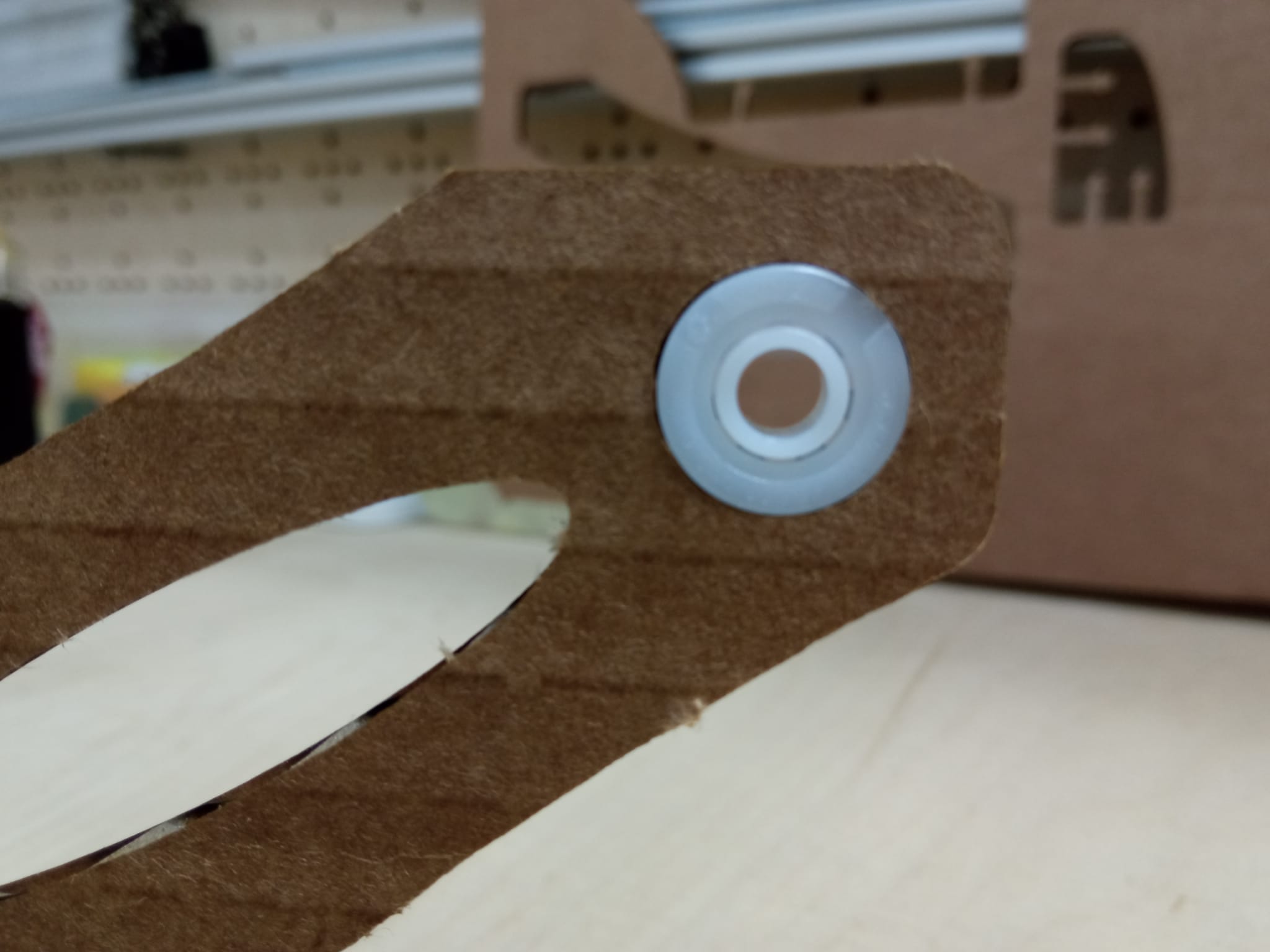
A 3D print of the tool axis that is fixed to the support with two plastic ball bearings.
-
Two belt drivers and a belt to make the tool axis turn from the engine. We are testing the sizes of the belt-drivers and how they affect the force of the impact.
-
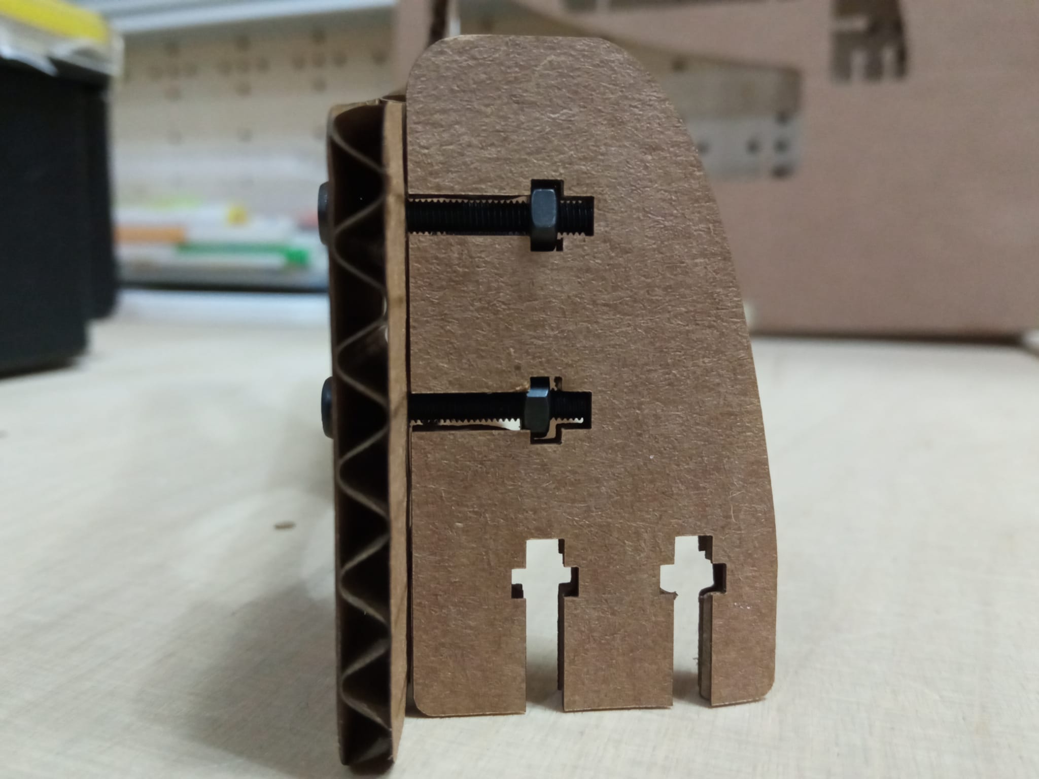
The support of the tool aixs will be fixed to the base with this joint system.
-
The ending of our tool which is too light at the moment. we have tried two different types of strings to see how they affect the force of impact with the button. Both ways were too light.
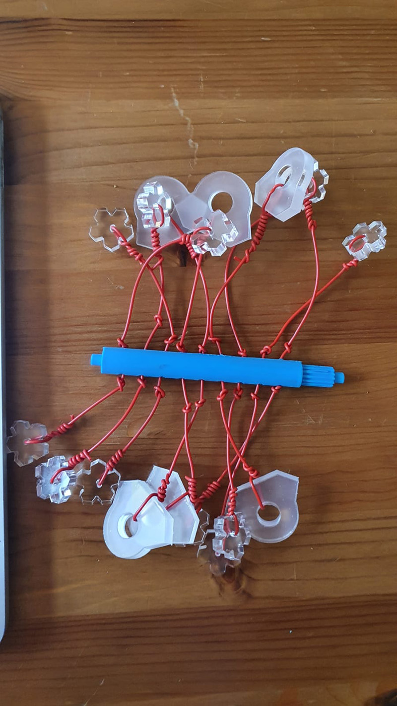
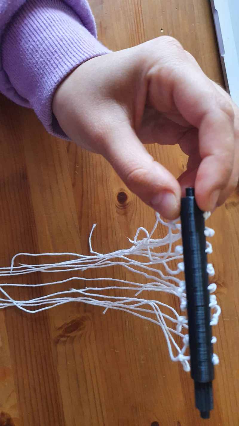
Eventually, after trying multiple threads, we used the most rigid one, so that the threads do not get tangled while rotating or after rotation of the axis has stopped.
This is why we have decided to three 3D print a piece that will be heavier and might have a bigger impact using the lighter thread.
The shape of the ball at the end of the thread was an imitation of the actual mine flail. Also, we wanted to have edges that would help click that button.
Running the tool
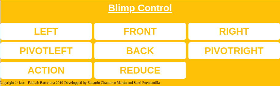
To run the tool we just used the function we added in the code to run the 3rd axis motor through a button we modified on the html code.