machine
common part for all teams

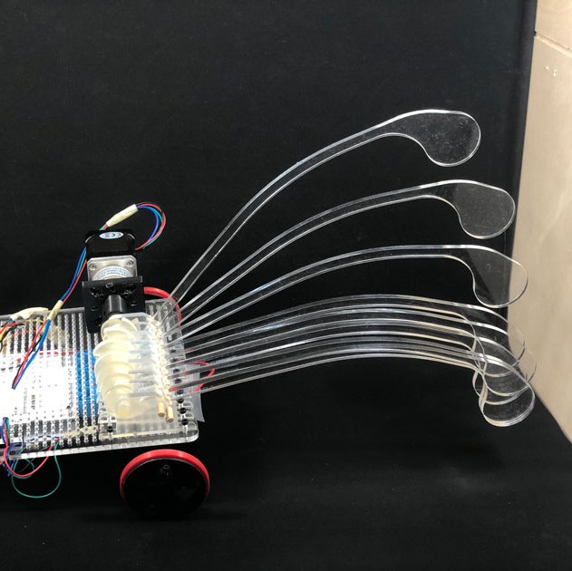
The body was the core part of our machine design project as it had to comply with all the rules we've defined as a group and at the same time leave some room for each group to add its individual and "secret" touch.
Here he define explain the process of the different parts that were developed. As explained before other Team's members also contributed in this part. Therefore I'll be explaining all contributions as well.
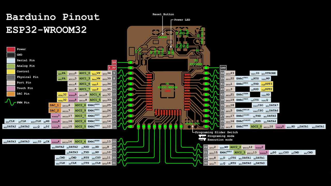
 Once we knew what features we wanted our machine to have we decided which board + circuitry we were going to use.
Our Team member Carla worked on a set of instructions to share with all the Teams on how to setup the Barduinos and CNC shields.
Once we knew what features we wanted our machine to have we decided which board + circuitry we were going to use.
Our Team member Carla worked on a set of instructions to share with all the Teams on how to setup the Barduinos and CNC shields. Find here the instructions:
WHY? Interface FTDI-USB* Fabbable Yes CNC Shield Compatible Yes
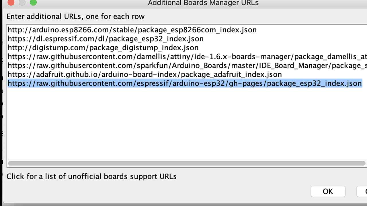 4 - Install ESP32 Espressif on Board Manager
5- Reading installations instructions from the Six Pack milling machine:
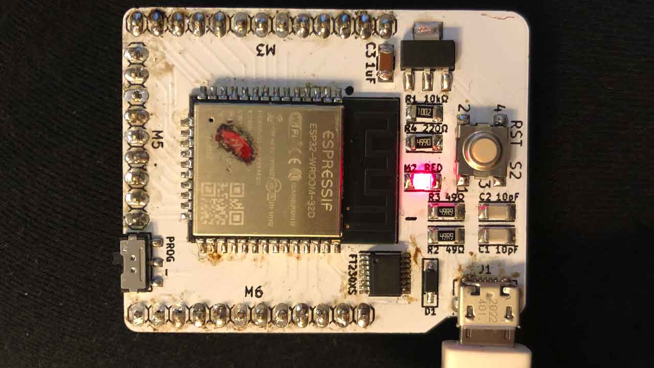
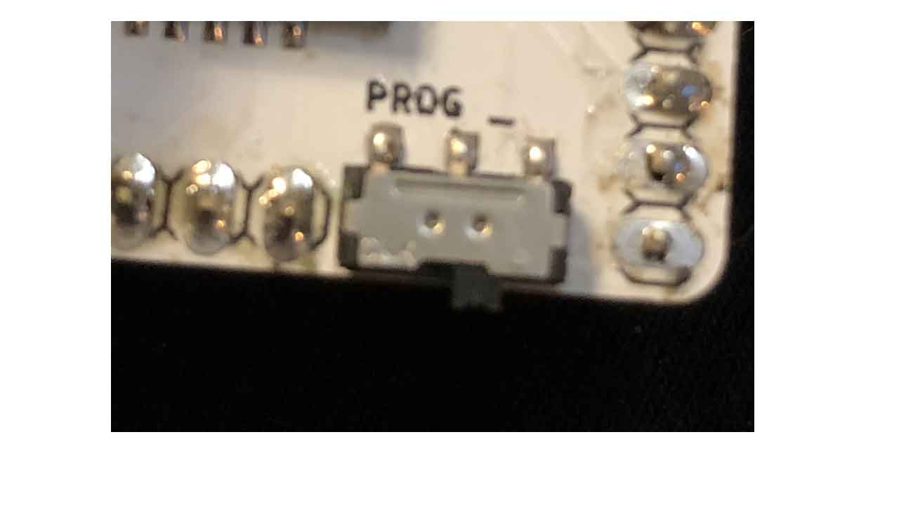
Before 6 - Make sure that before you connect the board the switch is on programming mode.
6- Original Grbl documentation says to remove the barduino board from the shield to program the firmware to prevent any possible damage to the shield. Connect the board:
4 - Install ESP32 Espressif on Board Manager
5- Reading installations instructions from the Six Pack milling machine:
Before 6 - Make sure that before you connect the board the switch is on programming mode.
6- Original Grbl documentation says to remove the barduino board from the shield to program the firmware to prevent any possible damage to the shield. Connect the board:
 7- select board. ESP32 - dev Module
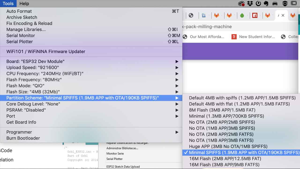
8- change Partition scheme to Minimal SPIFFS
7- select board. ESP32 - dev Module
8- change Partition scheme to Minimal SPIFFS
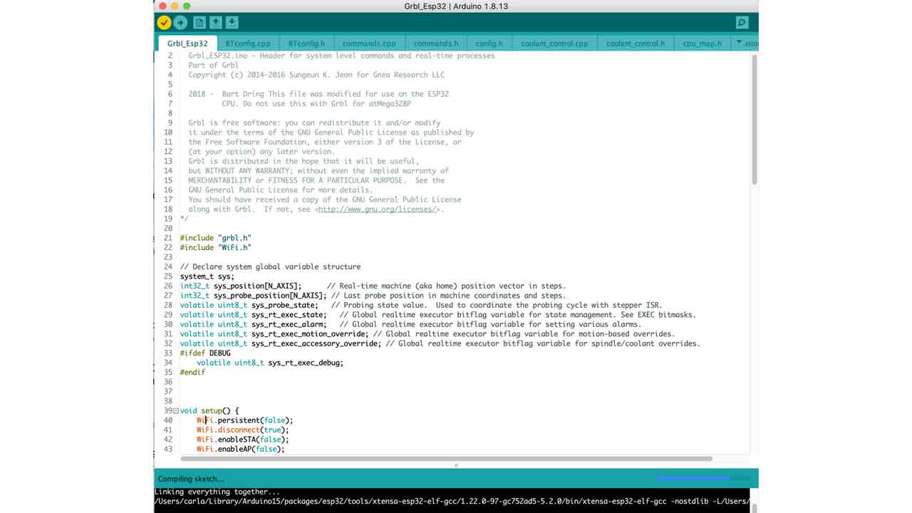
 9- Compile Firmware Arduino File - it will take a while depending on the machine.
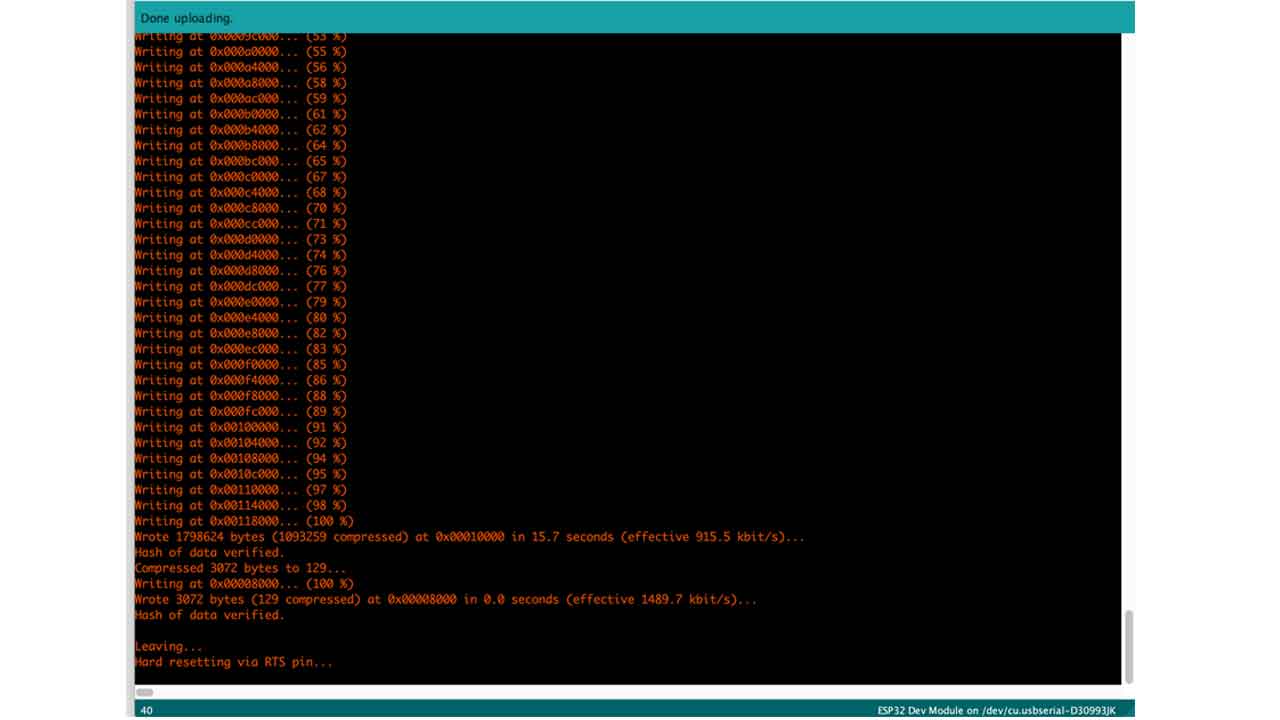
 10 - Upload the code
 11 - Disconnect the board.
12- Change the switch to Execution Mode
11 - Disconnect the board.
12- Change the switch to Execution Mode
 13 - Check for the ESP32 wifi connection. Select Wificonfig.h file to see the Wifi connection details or check screenshot here:
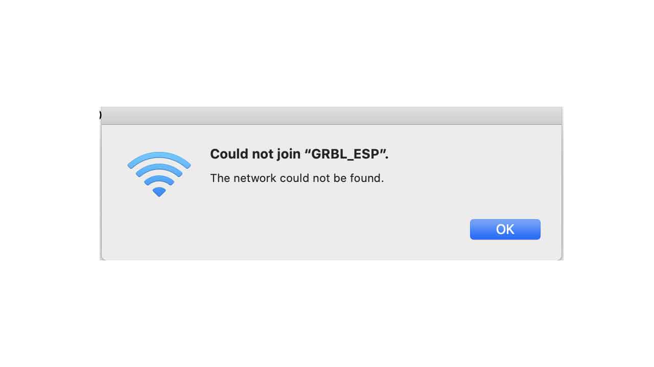
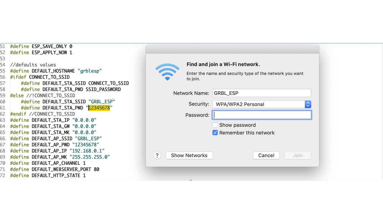 If you try to do it on programming mode, it won’t work:
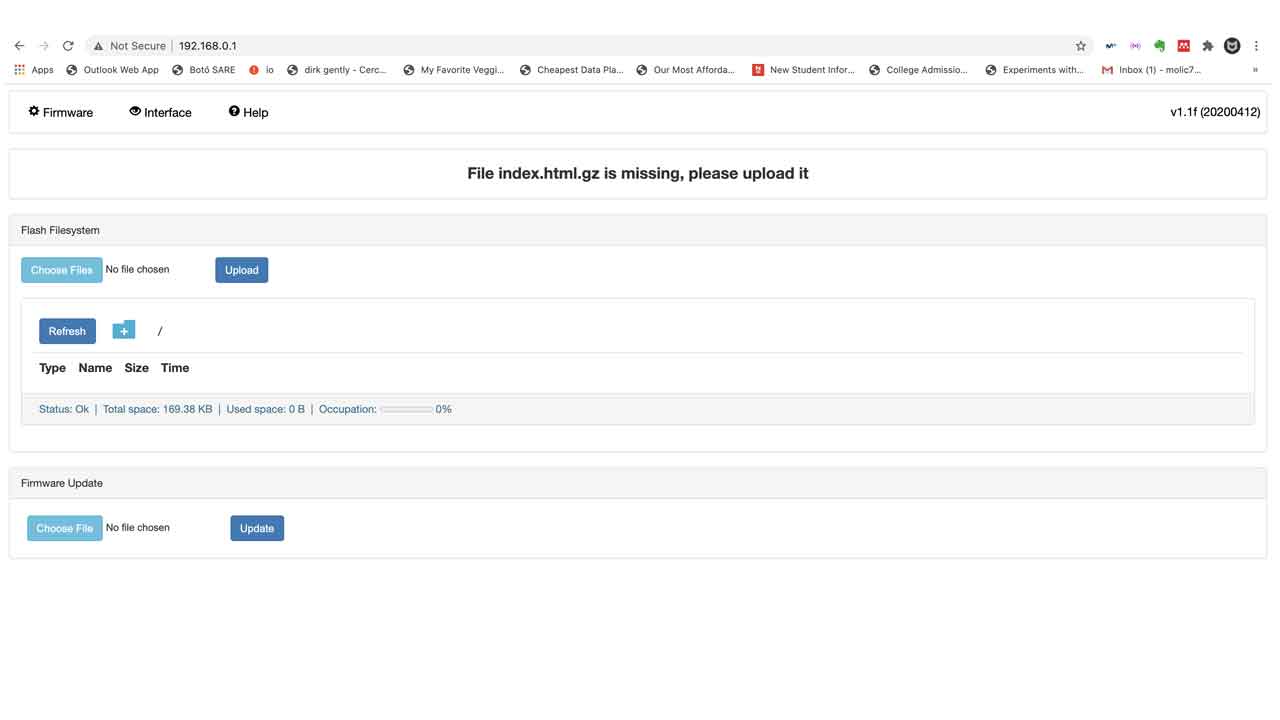
 14 — This is the page that pops-up on MacOS (also probably on Windows, too). It will show you the main website of the board. As it’s not a fully functional browser, close it.
Using your browser of preference, visit 192.168.0.1. Make sure you are still connected to the wireless network GRBL_ESP.
14 — This is the page that pops-up on MacOS (also probably on Windows, too). It will show you the main website of the board. As it’s not a fully functional browser, close it.
Using your browser of preference, visit 192.168.0.1. Make sure you are still connected to the wireless network GRBL_ESP.
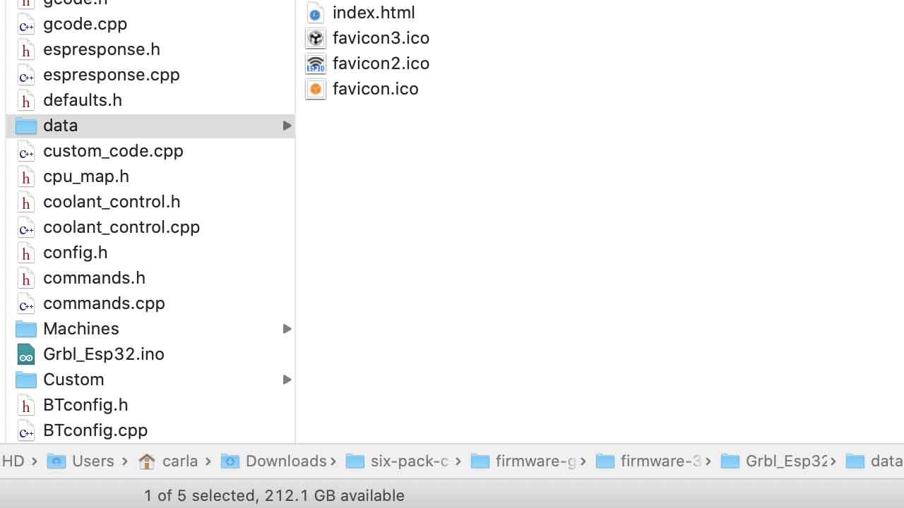
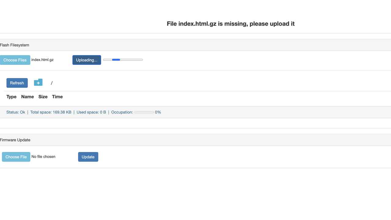
 15- We need to upload the index.html.gz file from the data folder that was on the firmware files. Thanks to Tue and David from 2020 Barcelona Fabacademy who had an awesome documentation:
16- After finding the file —> Go to 192.168.0.1

16- After finding the file —> Go to 192.168.0.1
17- It will say Uploaded 100% and a new button will appear “Go to ESP3D interface”. Click on it and it will take you to the motor control interface.

17- It will say Uploaded 100% and a new button will appear “Go to ESP3D interface”. Click on it and it will take you to the motor control interface.
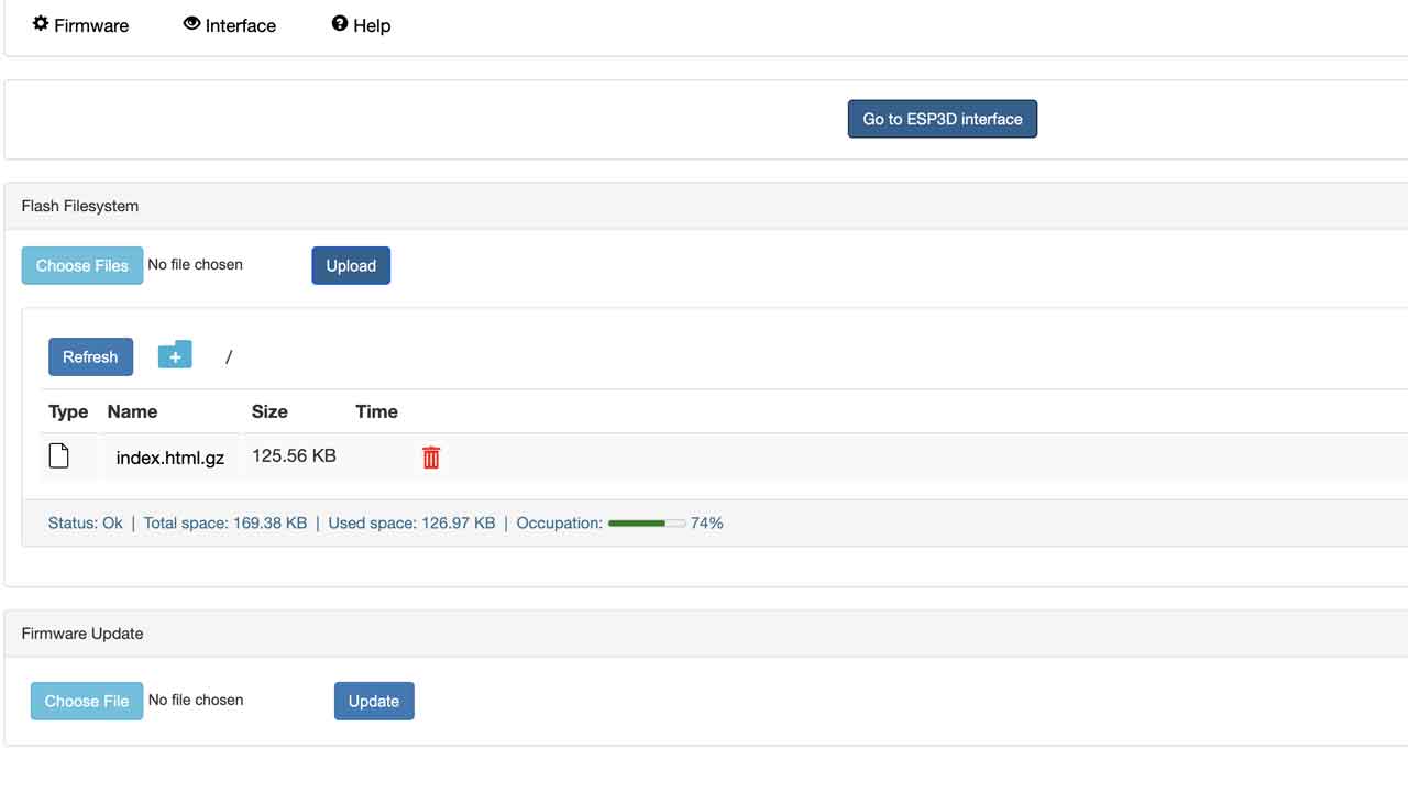 18- This is the cnc shield interface. Before pressing anything let's go back to hardawre.
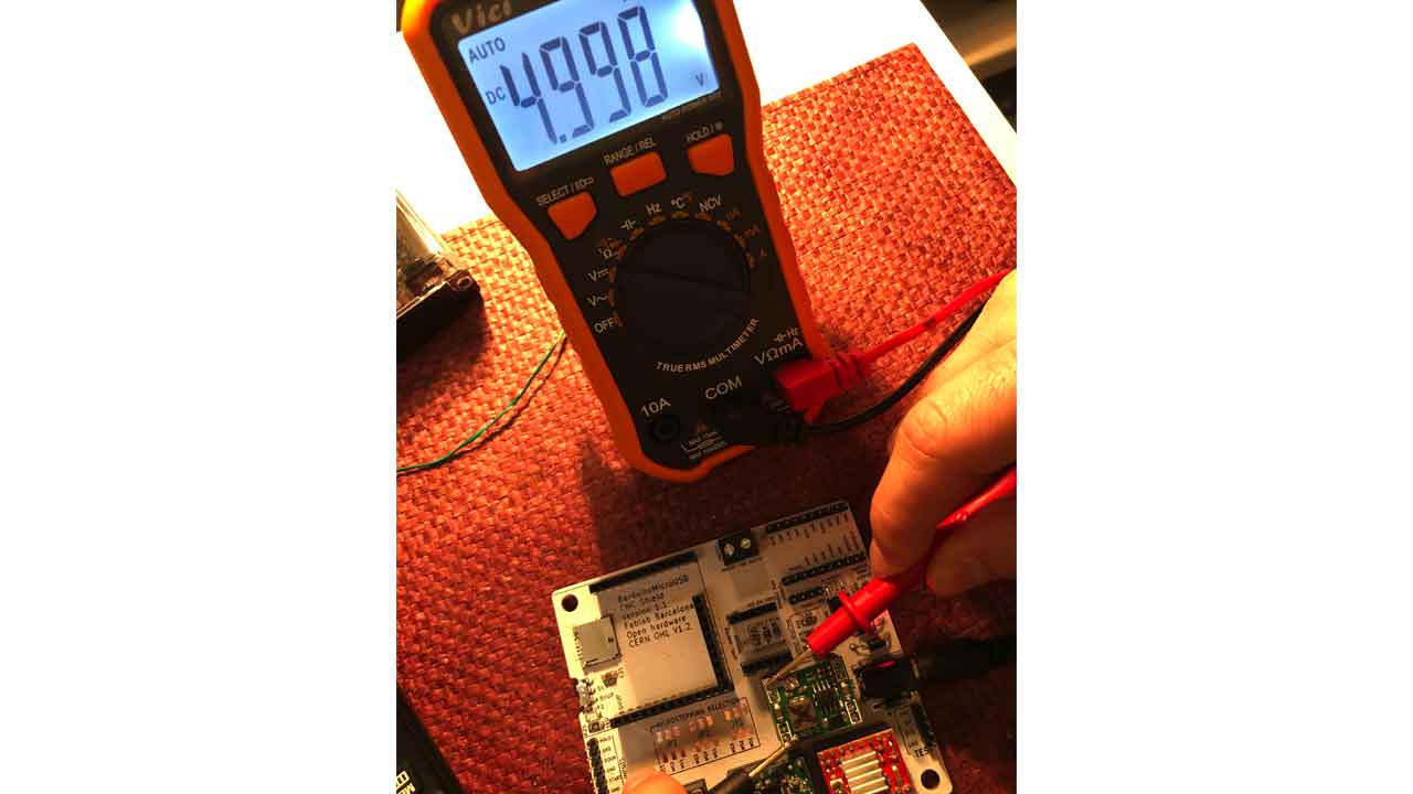
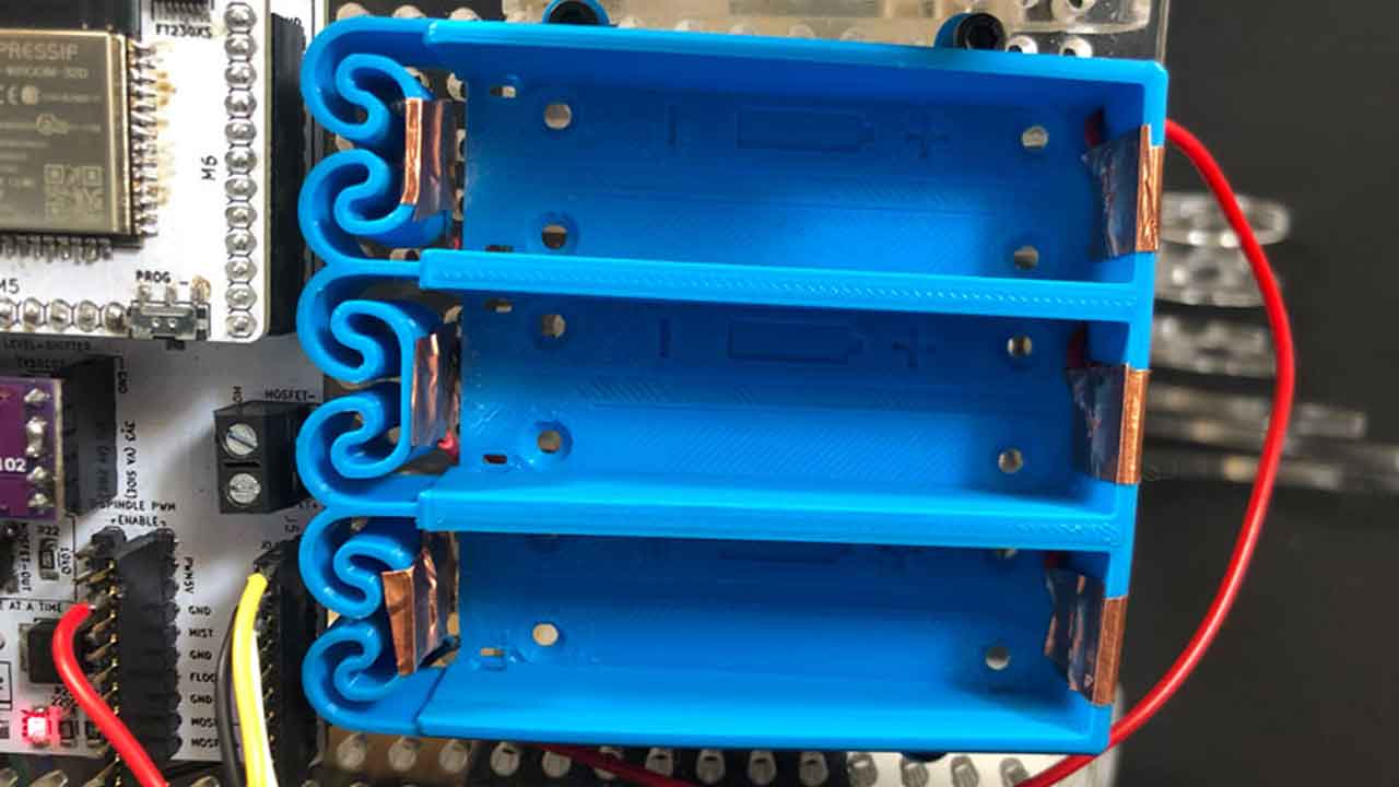
 19 — Check the Voltage of the Voltage regulator.
 20- - Now you can connect the Barduino to the driver board. Move the switch under the board to 5VUP before mounting the Barduino to the header pins.
 21 - WARNING - Time to setup the current limit for each motor driver —> Watch this video and come back
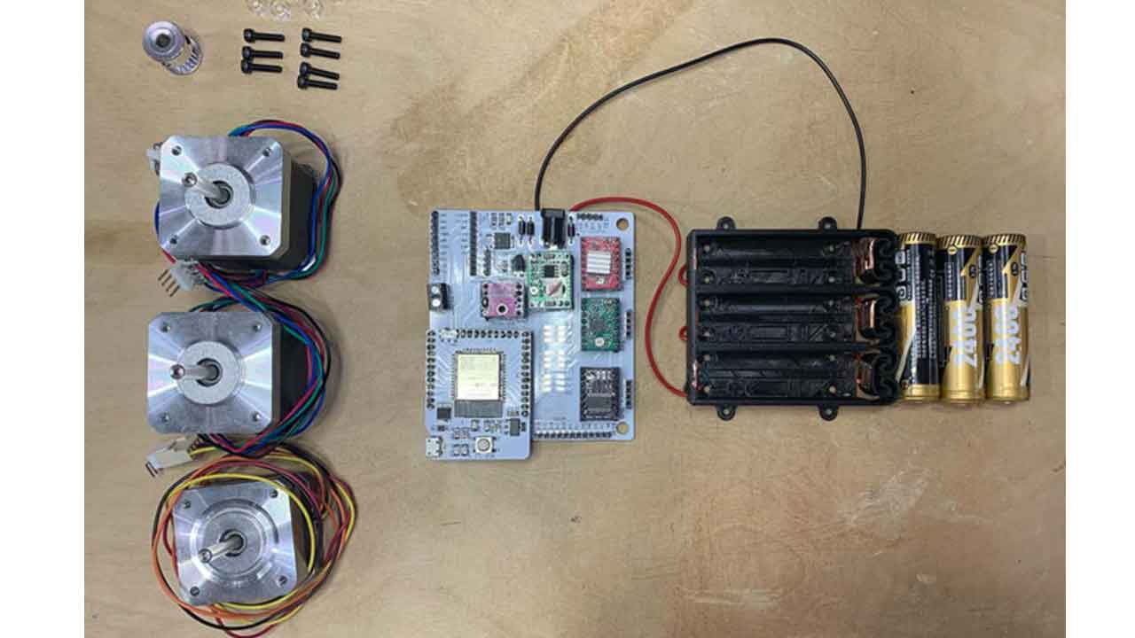
22- As you’ll see you need to check the specs for your motor, meaning NEMA 11, 14, & 17 might have differents specs. If we setup each motor driver according to its motor they won’t be interchangeable ( unless it’s the same model) or the motor could get damaged
21 - WARNING - Time to setup the current limit for each motor driver —> Watch this video and come back
22- As you’ll see you need to check the specs for your motor, meaning NEMA 11, 14, & 17 might have differents specs. If we setup each motor driver according to its motor they won’t be interchangeable ( unless it’s the same model) or the motor could get damaged
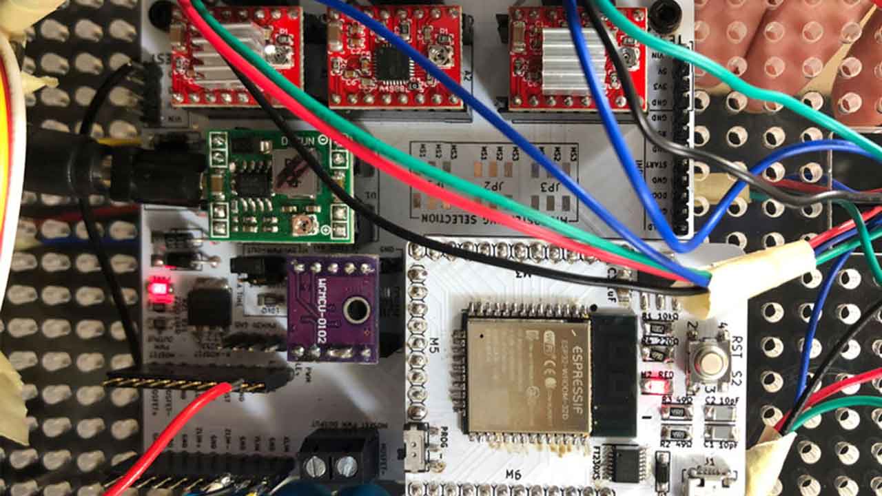
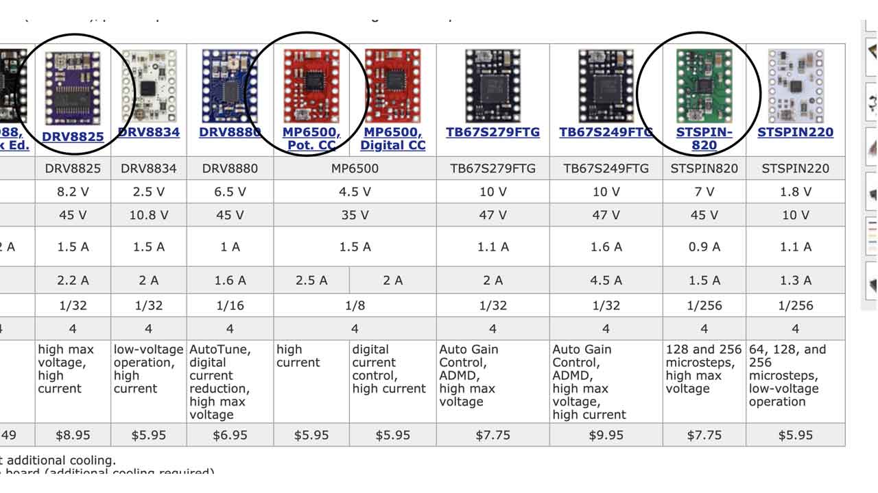 16A Purple one - Polulu driver DRV8825. The other two drivers look like knockouts of the other polulu models. I couldn’t find the specs
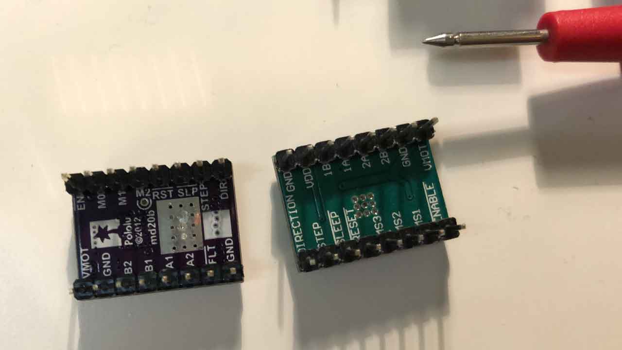
23- Not all have the same pinout orientation. —> Check for GND to match the shield .
16A Purple one - Polulu driver DRV8825. The other two drivers look like knockouts of the other polulu models. I couldn’t find the specs
23- Not all have the same pinout orientation. —> Check for GND to match the shield .
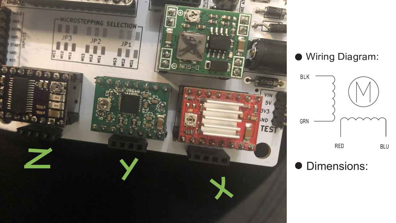
 For the NEMA 14- SY35ST36 —> The Voltage measured from the screw or VREF to GND needs to be around 500mV. Check this
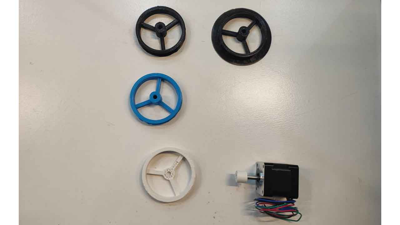
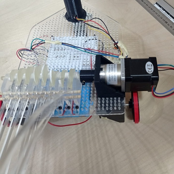
24- Time to connect the motor- Make sure that the power supply is desconnected. I connected the wires according the wiring diagram on the motor’s datasheet —> Black, green, red and blue.
For the NEMA 14- SY35ST36 —> The Voltage measured from the screw or VREF to GND needs to be around 500mV. Check this
24- Time to connect the motor- Make sure that the power supply is desconnected. I connected the wires according the wiring diagram on the motor’s datasheet —> Black, green, red and blue.
 25- Time to connect to the GRBL-ESP http://192.168.0.1/
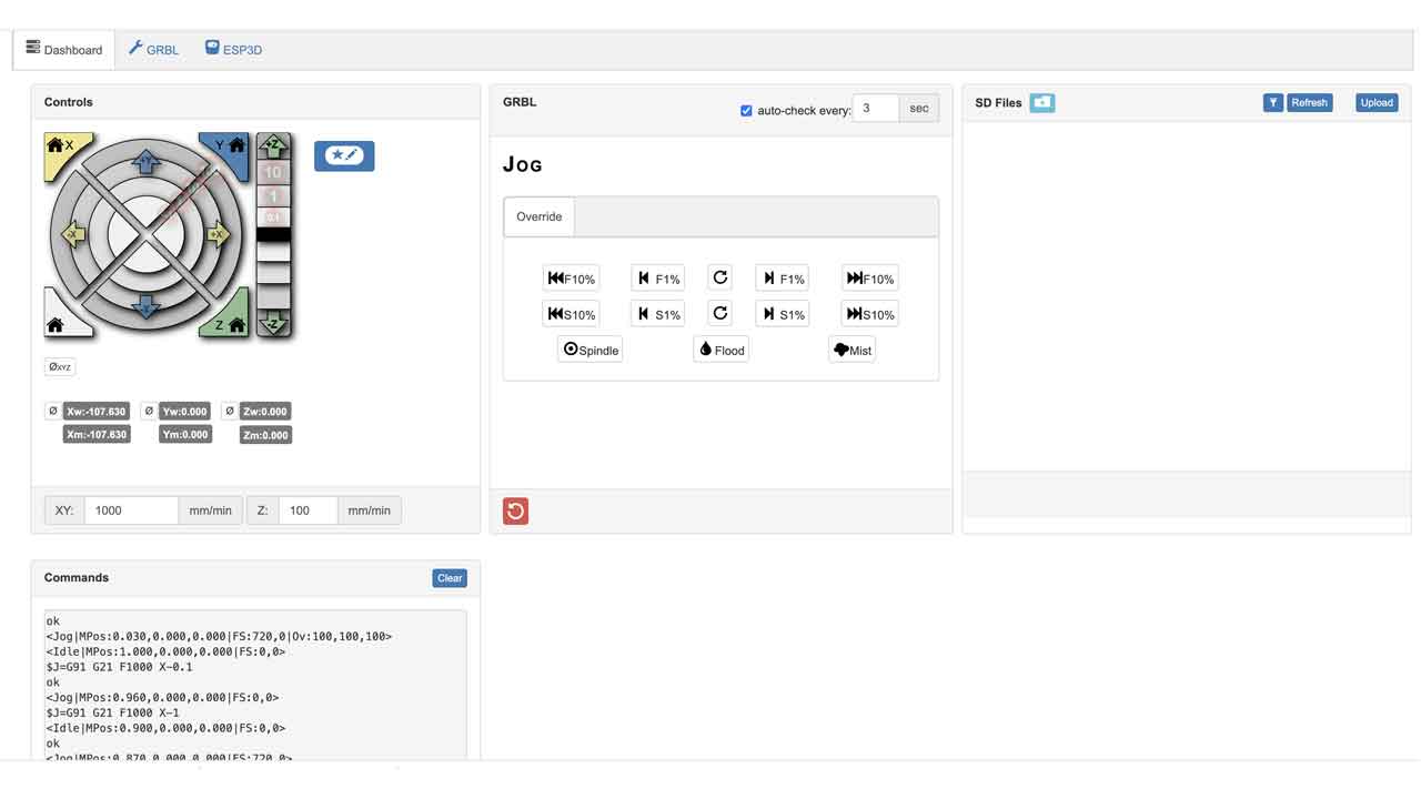 When sending the commands the motors moves. Not super consistently, as it seems that wiring is a bit flickery. Wiring should be checked, everything else seems to be working.
 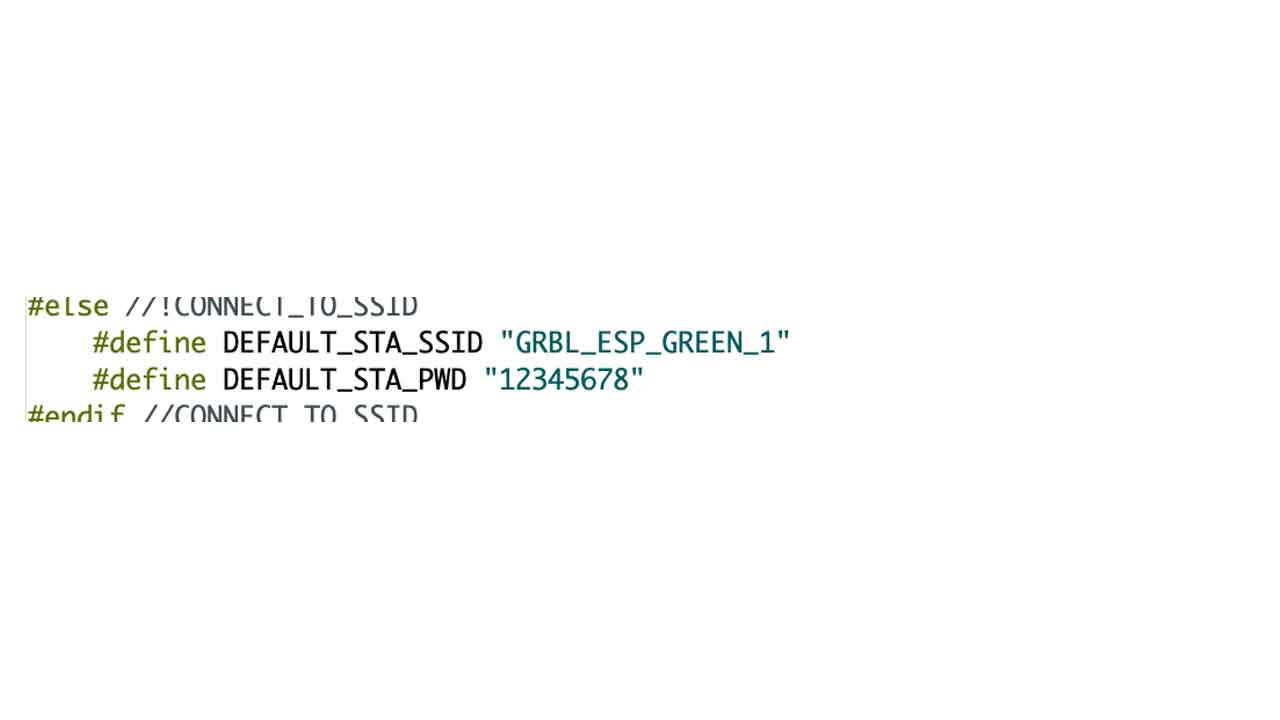 And this is for setting up the Barduino + CNC shield. There are many steps, but with this instructions, all groups were able to setup their boards.
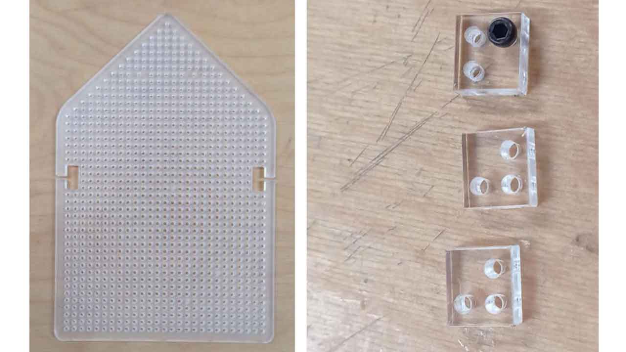
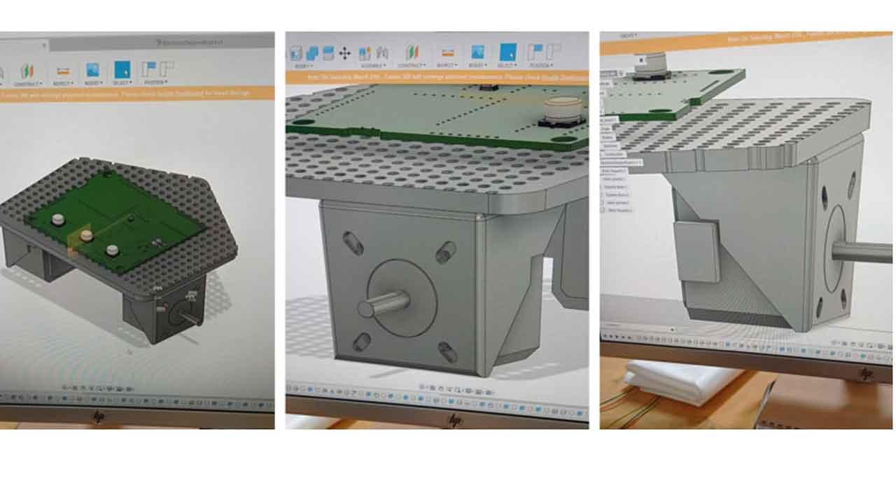 We ended up doing the final base using smoked acrylic. The fit test was key to make sure everything was tight.
common part for all teams
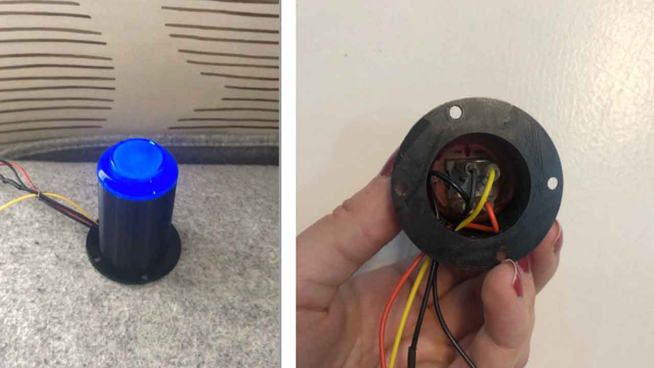
Our way of disabling other bots
back to home page