BODY
common part for all teams

In this page we are going to explain what tool we've decided to implement on our machine for trying to win the combat against our fab mates machines
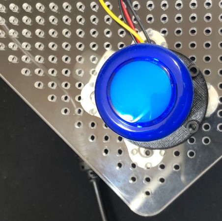
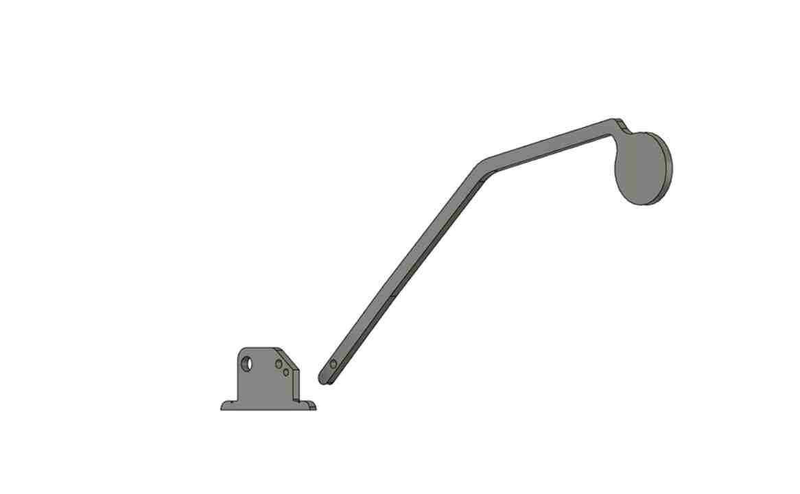
Thinking about which tool option would be the best, we came up with the idea of using a small hammer with a handle long enough to press our's opponent button
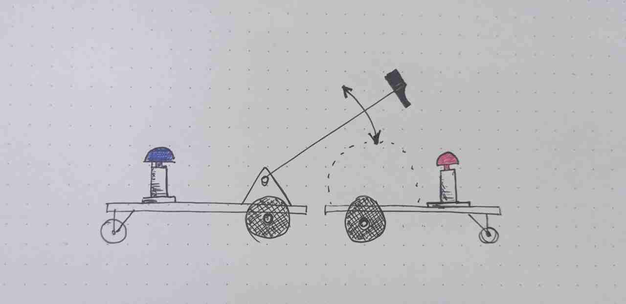
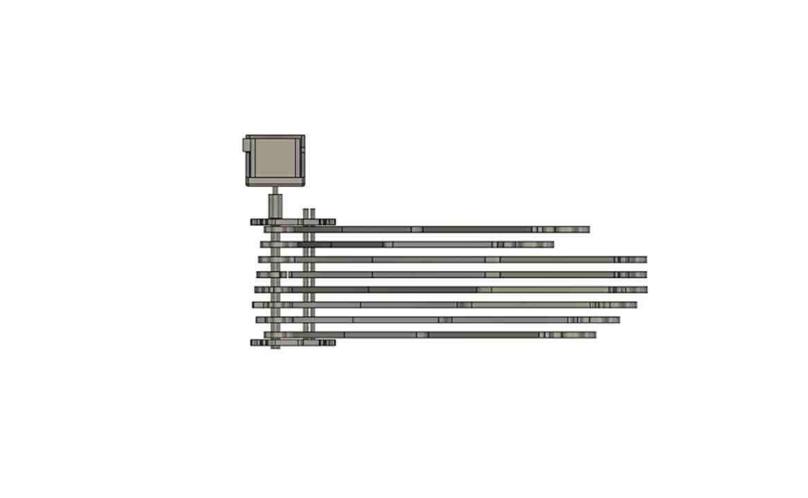
Once we knew which tool we were going to use 1, we thought about how to transmit the movement, for this we thought about using an eccentric cam 2.
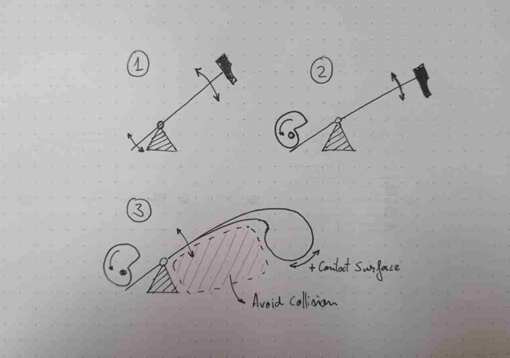
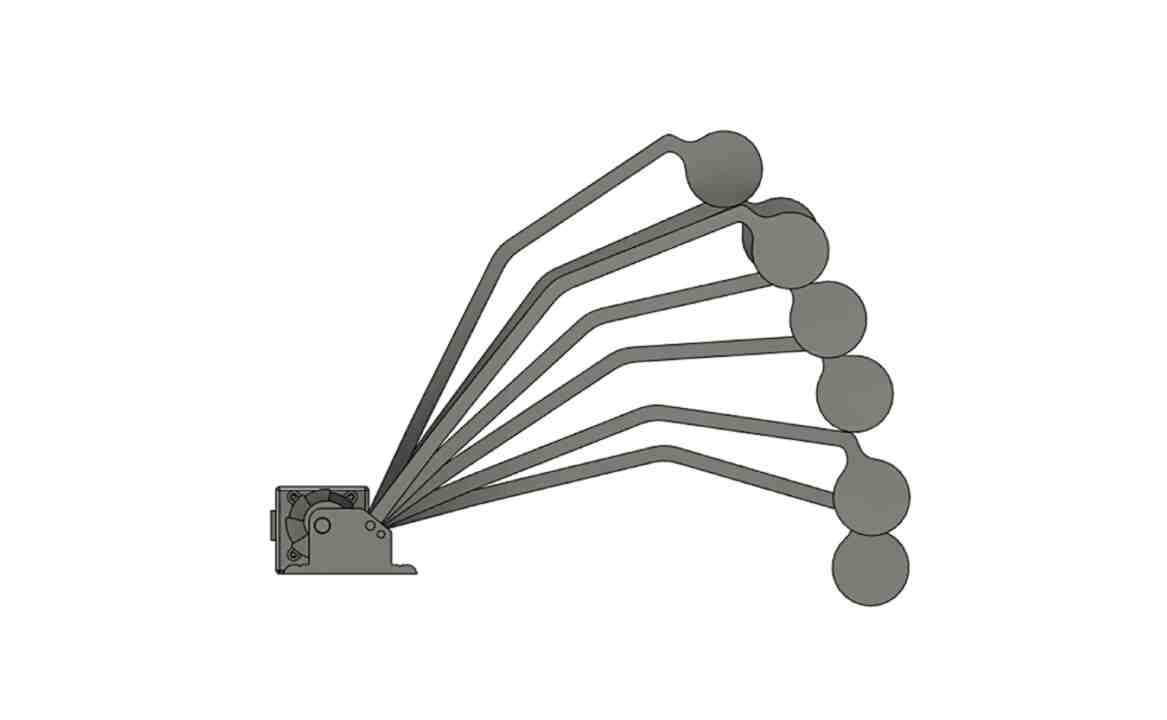
On the other hand, we also work on optimizing the hammer geometry to increase the probability of a pulse and decrease the probability of collision with the opponent's tool 3.
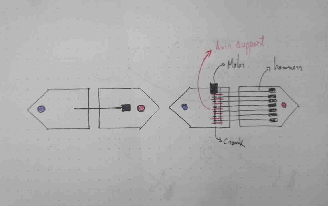
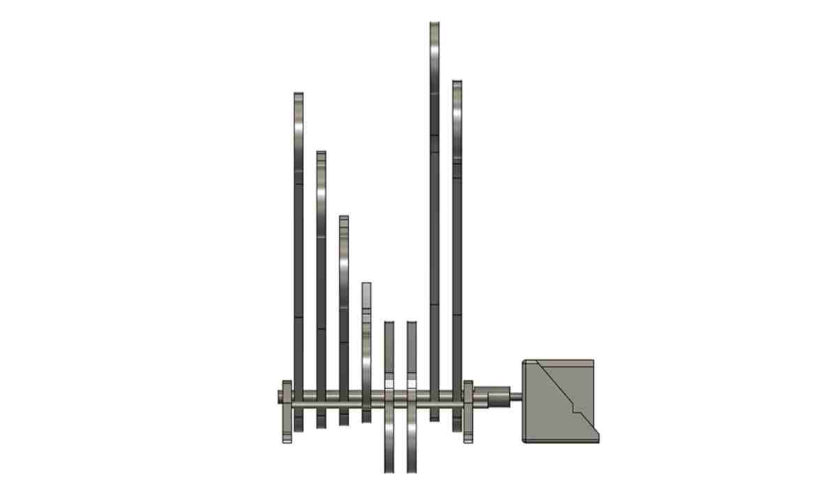
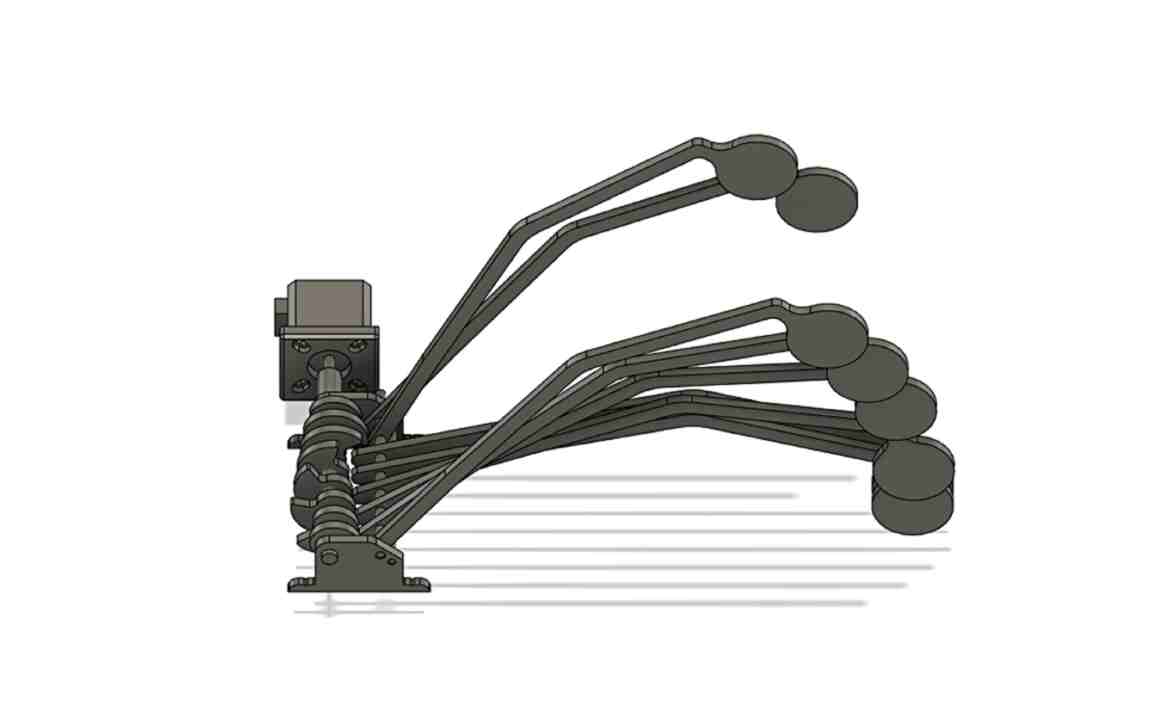
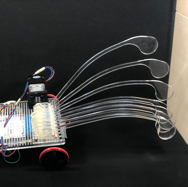
Finally, to increase the probability of pressing our opponent's button, instead of using a hammer, we decided to align various driven by a motor connected to a camshaft
To test our idea, we decided to quickly build a first prototype to confirm that we were on the right track.
To make the design, we used Fusion 360, and from the design of the base we start modeling the different components of the tool.
To build up all the commponents of the tool we used different manufacturing processes
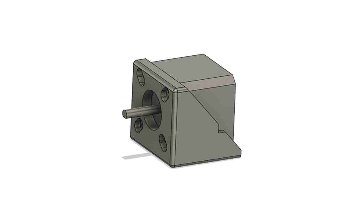
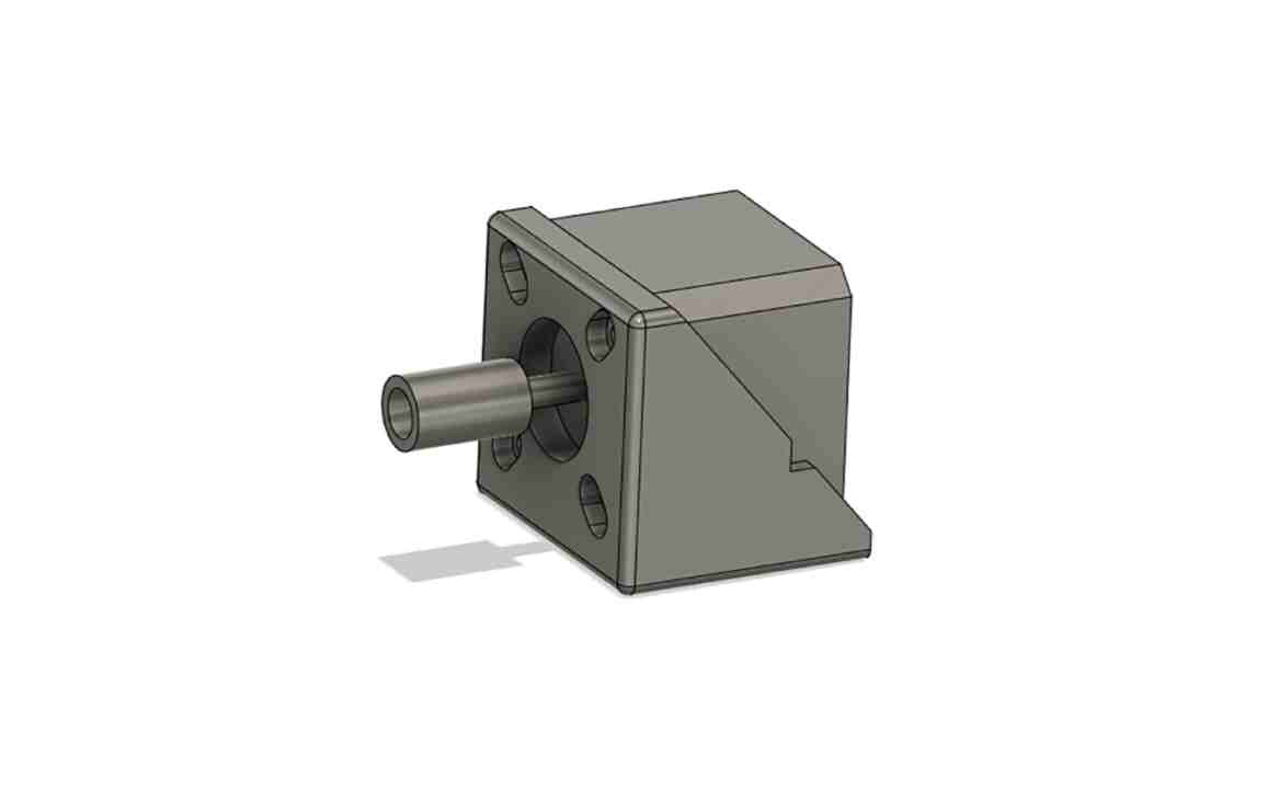
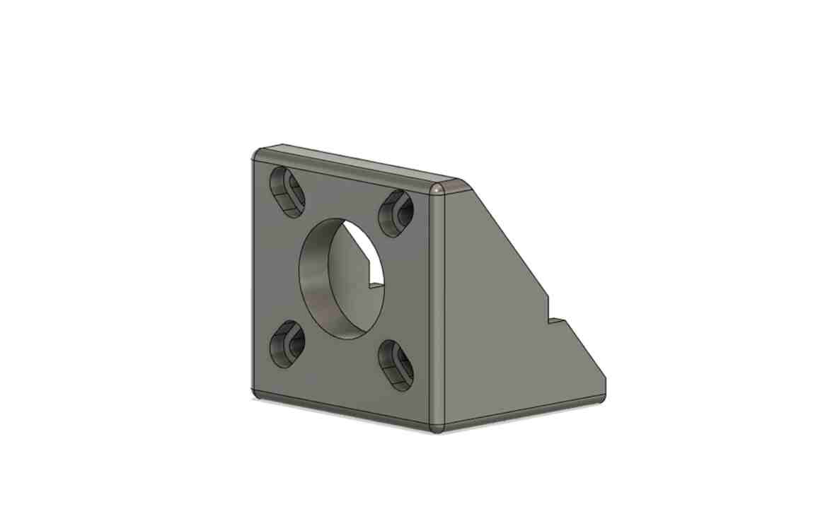
MOTOR SUPPORT
to build our Motor support we used a Mark two an FDM 3D printer. This printer can print composite materials like nylon with glass fiber, keblar or even carbon fiber

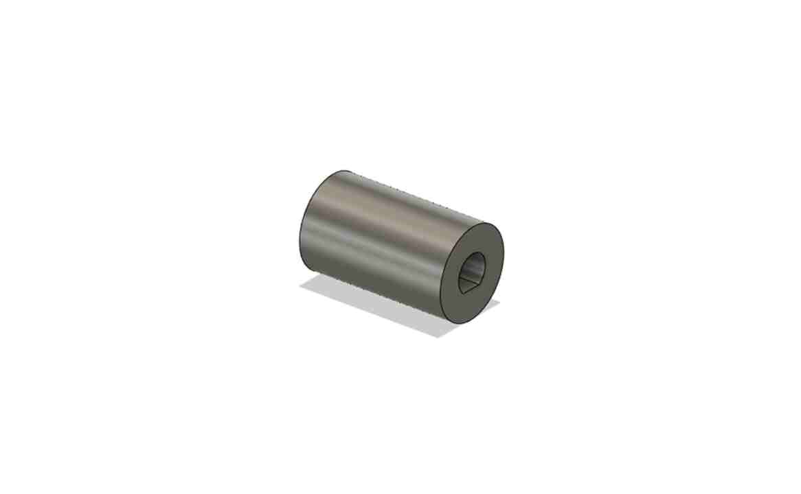
CRANK CONNECTOR
For the connector that will transmit the rotation movement of the motor to the crank, we worked with a Prusa MK3 an FDM 3D printer and PLA as a material

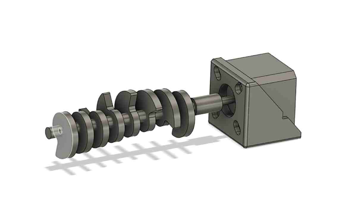
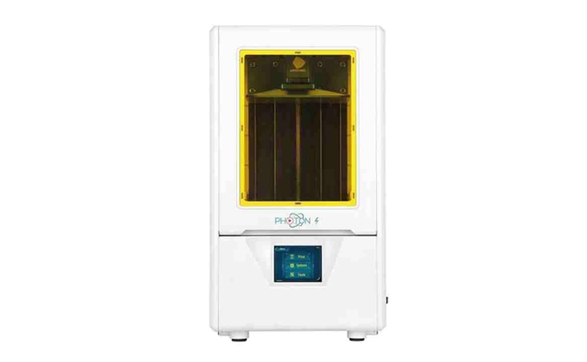
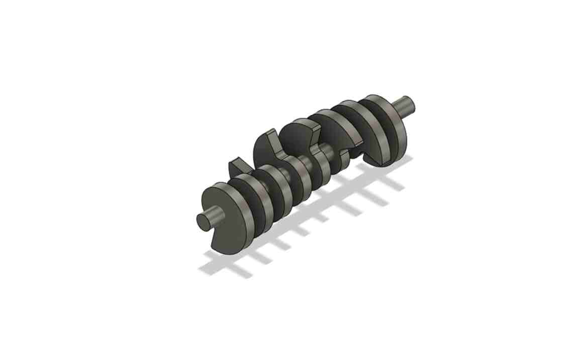
CRANK
Due to the complex shape of the crank, finally we decided to print all the crank as a whole piece using SLA 3D Printer, the Any Cubic Photon.
By using this method, our piece suffered some deformations, which later affected the movement of the tool.
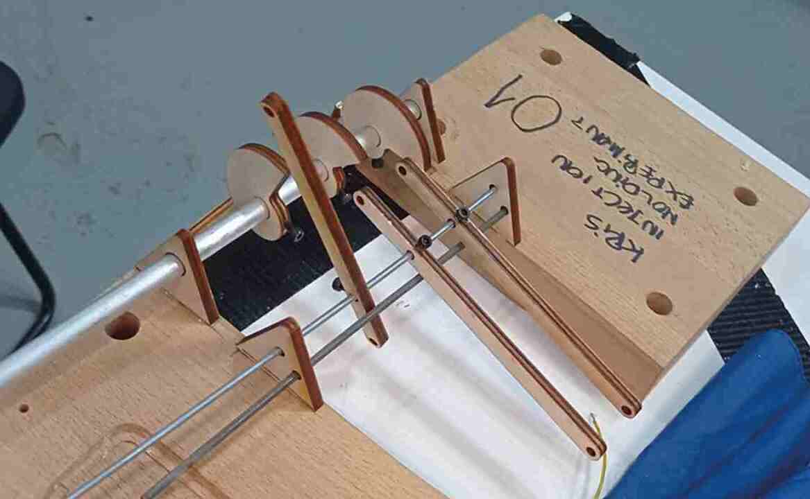
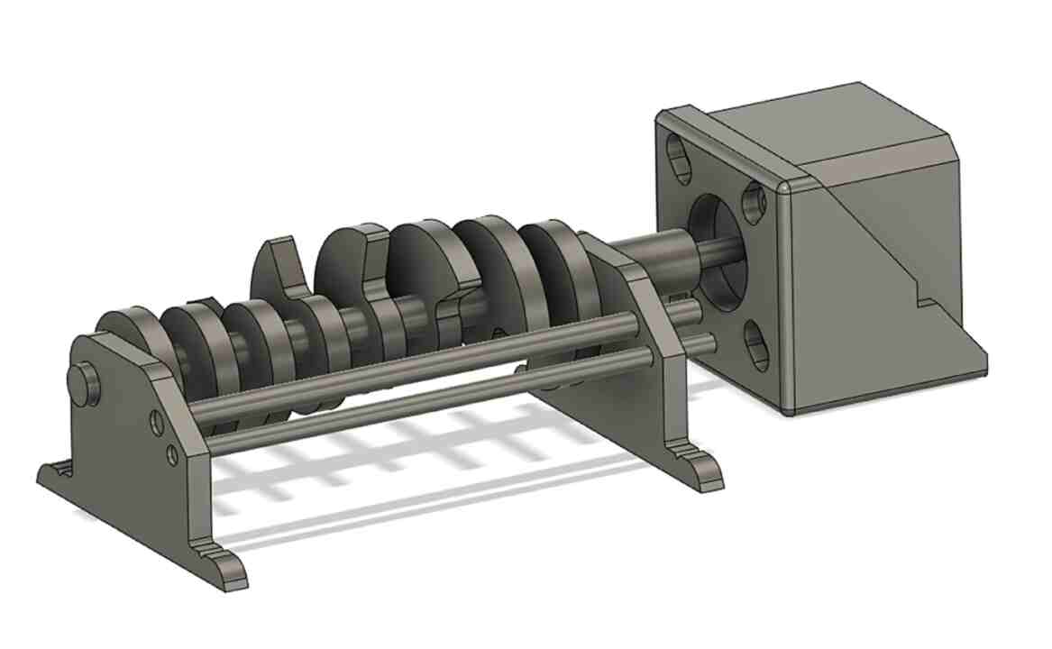
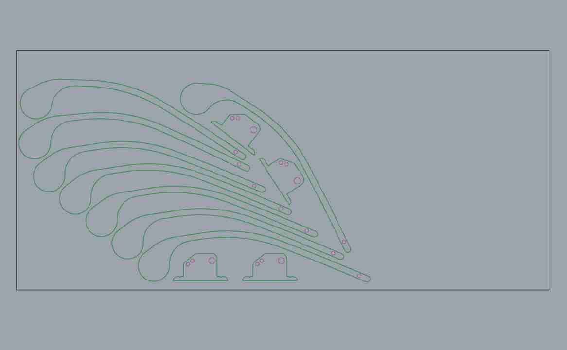
SUPPORTS & HAMMERS
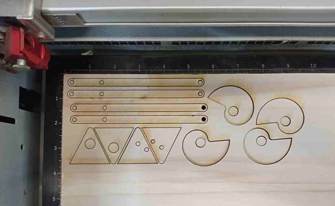
Finally, for the manufacture of hammers and supports, we use laser cutting as a manufacturing system. The material we used for it was 5mm transparent methacrylate
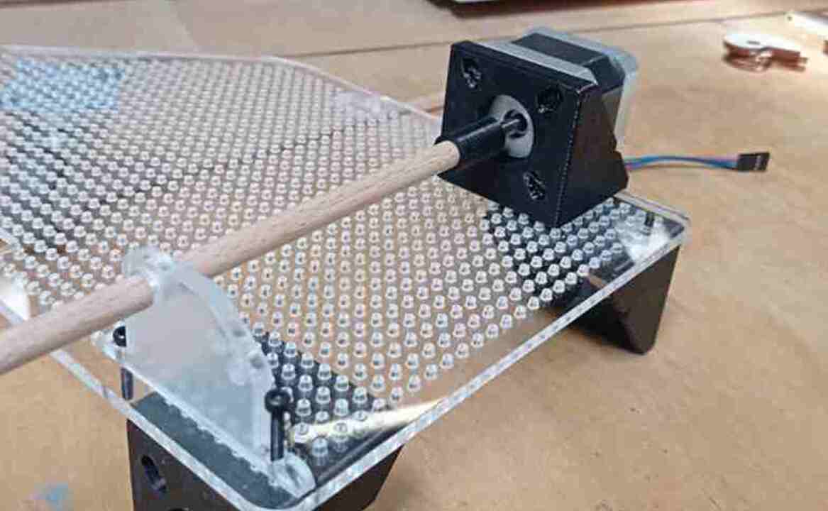
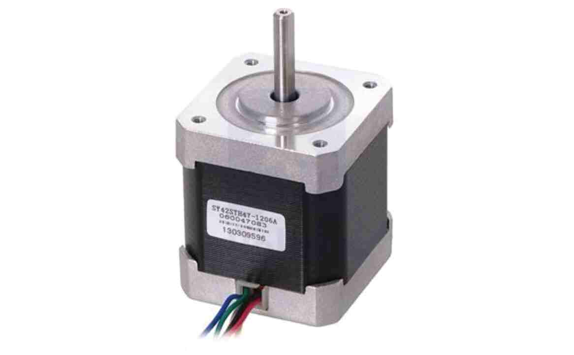
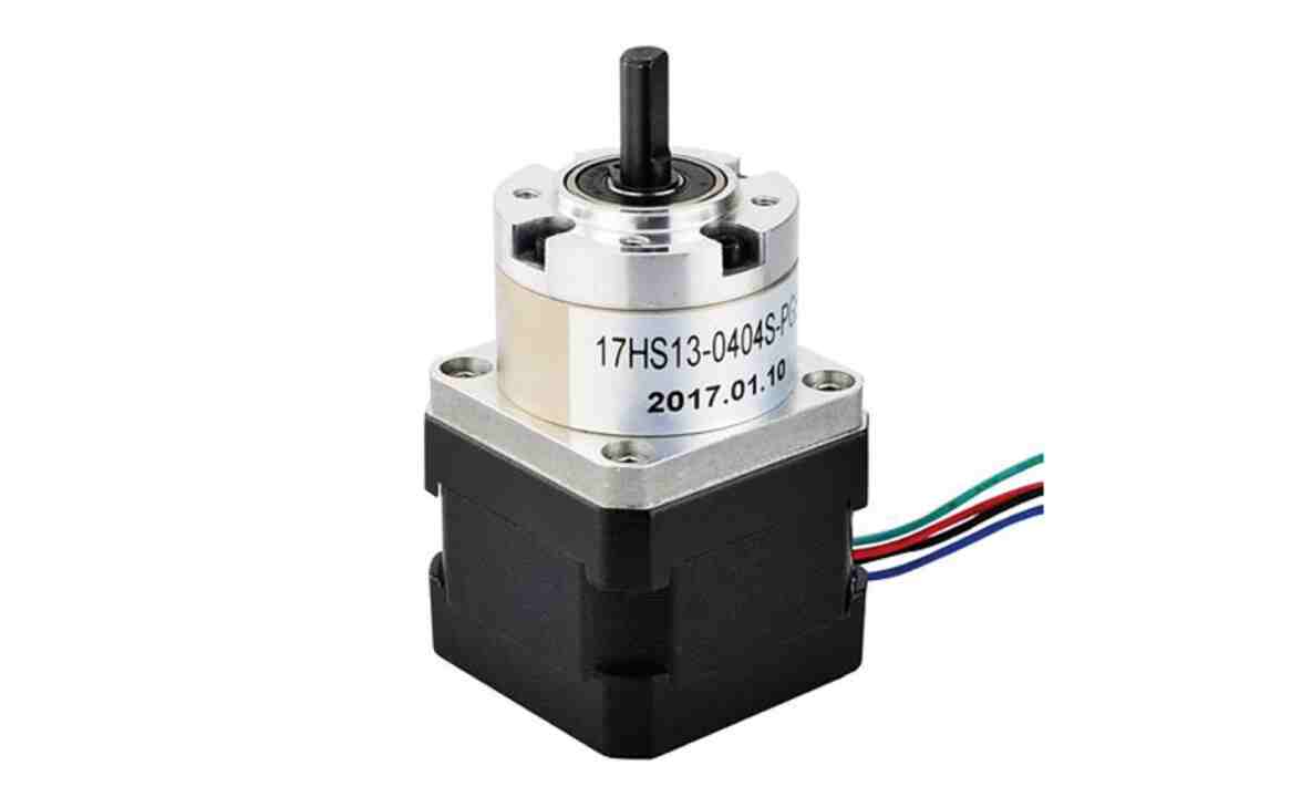
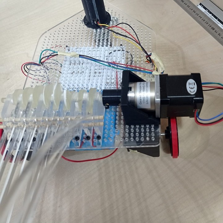
MOTOR
Regarding the motors, we had to make a change because due to the misalignment of the supports with the crankshaft, the friction was so high that the
stepper motor we chose could not offer enough force to move the tool.
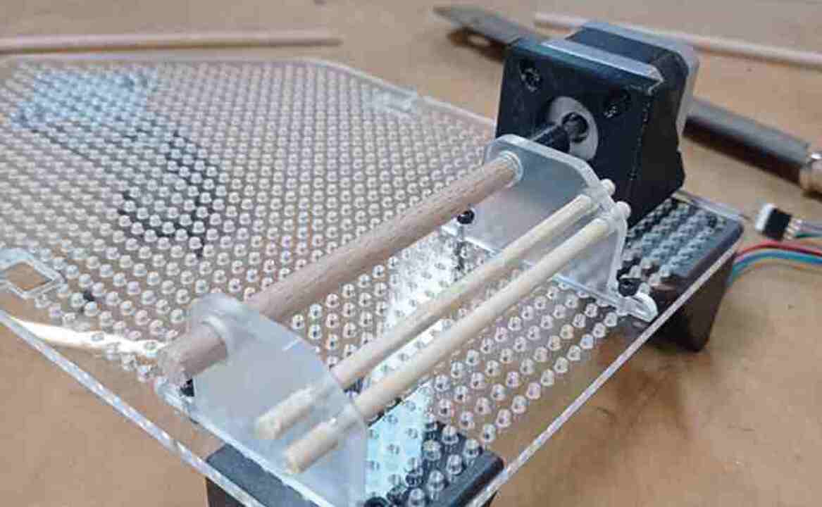
To solve this, we decided to replace the motor with a motor with a reducer, which offered us greater torque and was able to rotate the crankshaft.
In the following videos you can see the behavior of the different engines.
common part for all teams
common part for all teams
back to home page