BODY
common part for all teams
In this section of the website we will explain the rules of the game and how we will adapt them so that all teams are aligned; and our way of dividing the work between us. It seems to us a good way to establish the bases so that the work is orderly and equitable among all.
We were inspired by battle bots, to generate a "combat" game where the robots must deactivate each other. The one that continues to function after the battle will win.
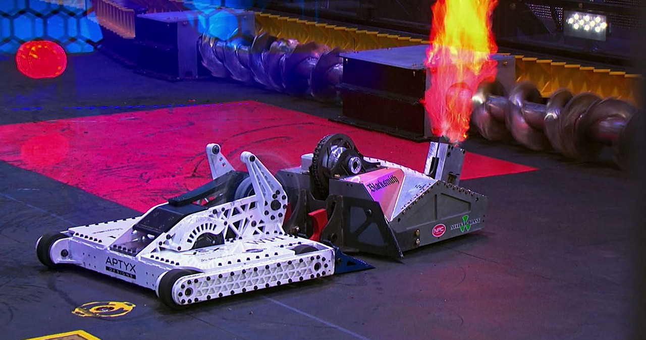
We don't like the idea of destruction, but we do like that there is a certain rivalry between the teams. We believe that creating a competition makes the groups more motivated and that our work will go further.
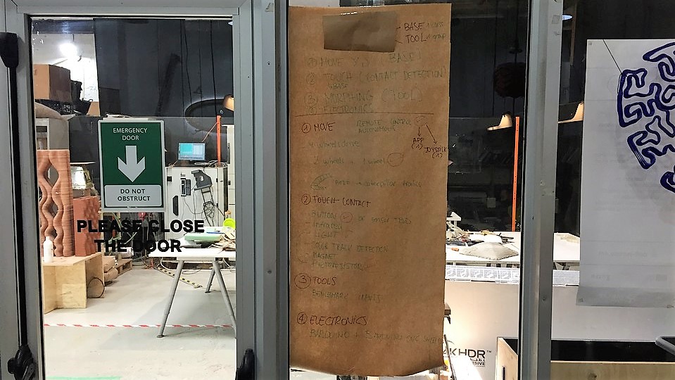
To really make a machine (we had an interesting discussion about whether a robot is a machine and vice versa), we established some basic rules that mark the following: together we will create a base on which we will assemble each team's machine (tool).
For the game to be fair and we were just discussing during one morning those aspects that all the machines had to comply with, how we could deactivate other machines and what materials we would use.
Here are the rules of the game that we finally decided.
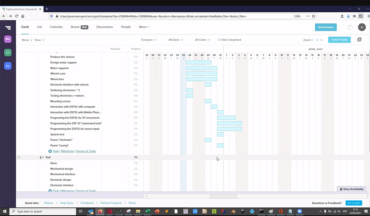
In the same meeting we decided how to distribute the work for the common part of the bot (base). We made a Gantt chart to organize ourselves better and each of us was choosing the tasks with which we felt most comfortable.
For a clearer view of the cast, here is a short list of what to do and who does it:
That is with regard to the division of tasks as Lab, and everything that corresponds to the common body. Now is the time to see how we distribute the tasks within our team.
In the buttons below you can see the personal page of each of the members so that you better understand how we have contributed to the development of the body and the tool.
In case you do not want to entertain yourself to enter our pages here is a small summary:
Carla was in charge of the electronics and the interface. I created this tutorial document to help my peers to assemble and setup their boards. HOW TO BARDUINO + CNC SHIELD
Marc was in charge of modelling the base for all the Teams and in addition he created a 3D model and simluarion of our tool. He also laser cut the bases and pieces for the crankshaft, 3D printed the motor supports.
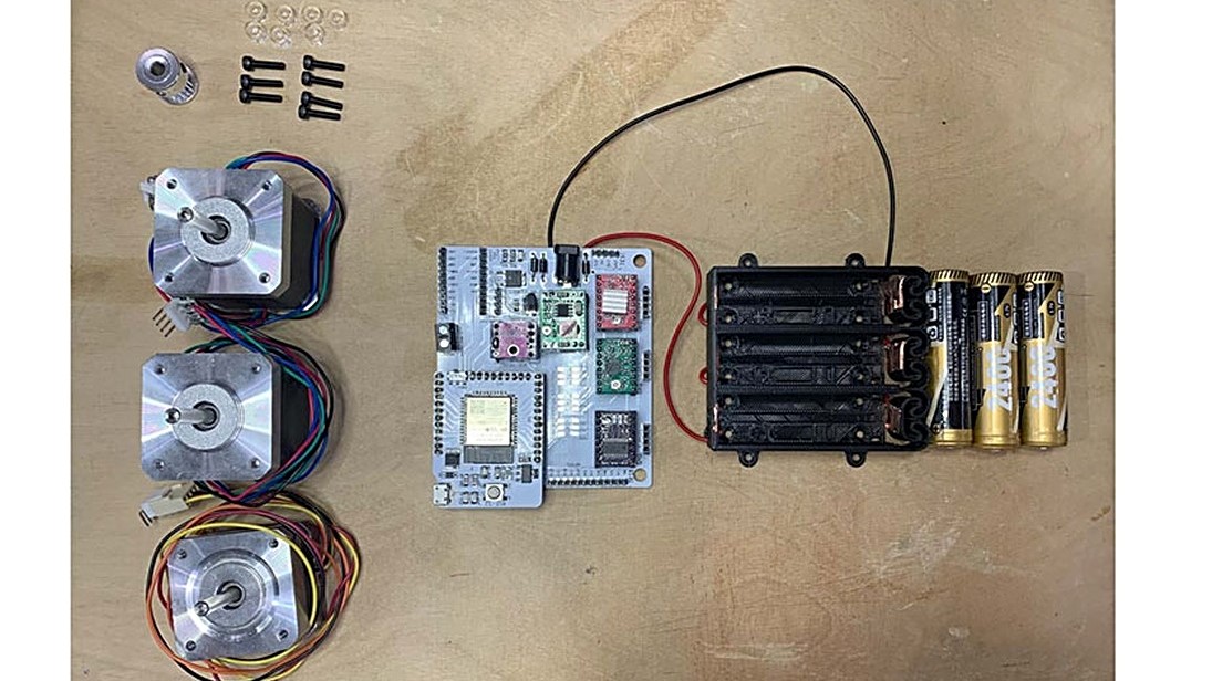
Nil was in charge of the crankshaft and making sure that all components coming from other class members were ready for us to build our Fabot. That included the battery pack, and recharging batteries.
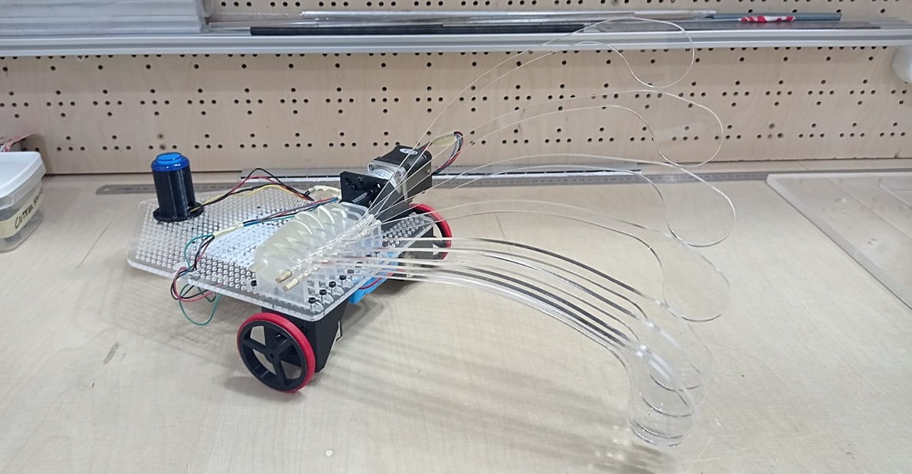
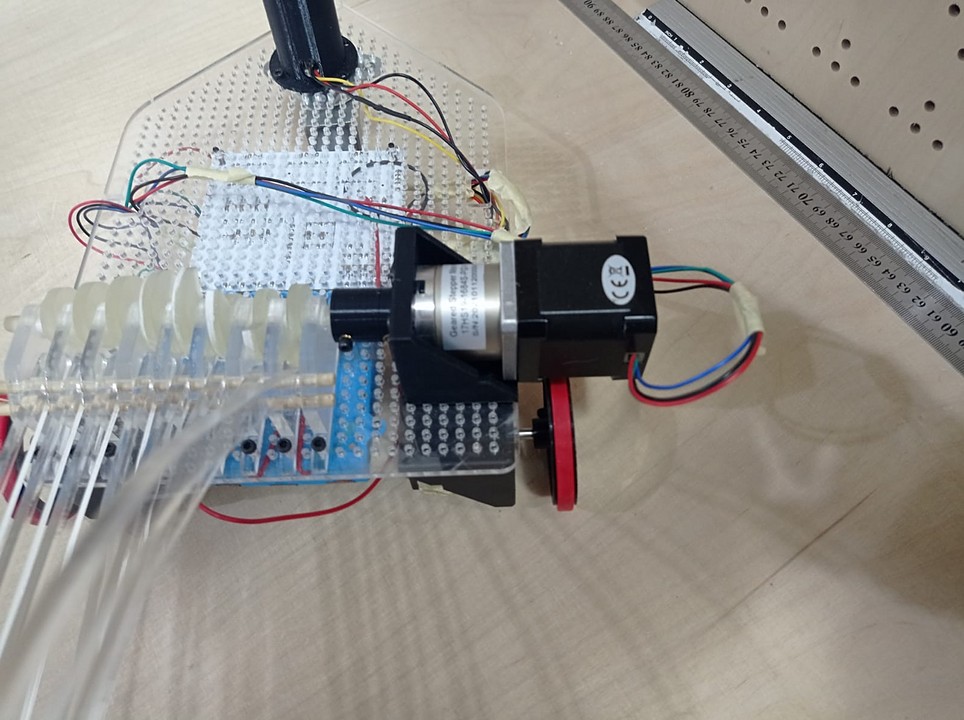
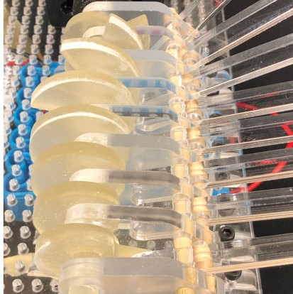
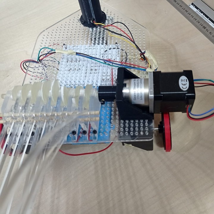
Although on the other pages of this website you can find in more depth the development and operation of the different parts of the machine, here you have a small visual summary of everything that makes up the machine.
Our tool is mounted on the common methacrylate base. As you can see, we had to use a motor with a reducer to be able to move the tool properly.
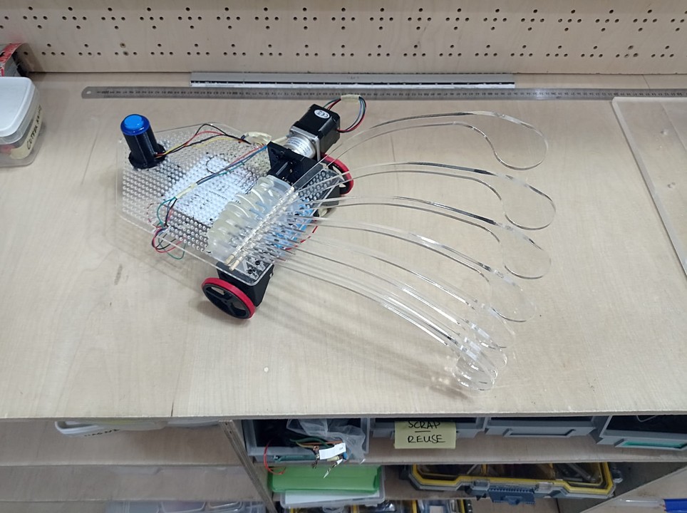
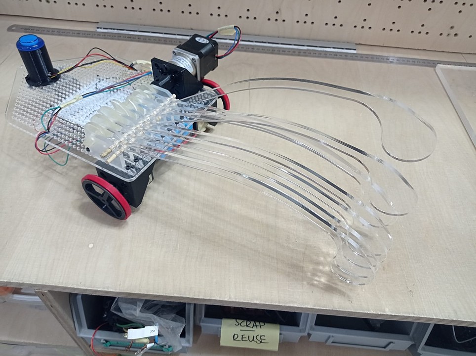
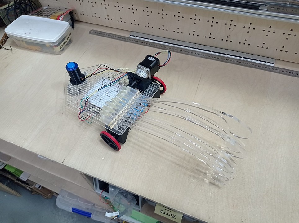
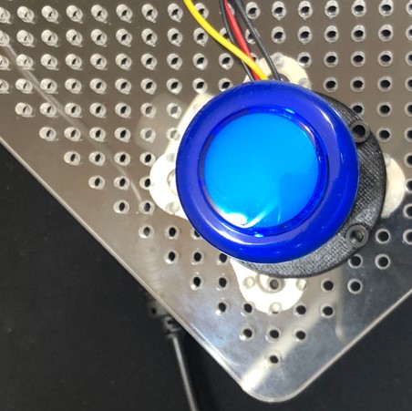
At the rear we find the free wheel that allows you to turn only using one motor per wheel. On the wheel in the upper part of the base, we find the luminous button that when pressed deactivates the machine.
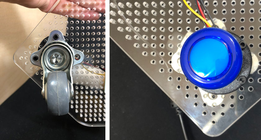
Below we also find:
Finally, there is only the interface that we use in smartphones to communicate in real time with the machine. It is a simple app (in appearance) that allows you to perform some predefined movements such as moving forward, turning, activating the tool ...
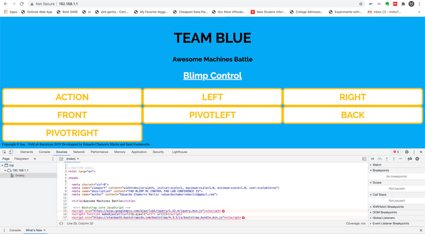
As you can see in the images of the app, we work from the one developed for the 15FAB conference and modify it according to our needs.
Below in the form of a list you will find those things that we consider have gone well:
As a general conclusion, we can say that the machine has worked correctly, the equipment has worked well, and that in general as LAB colleagues the experience has been satisfactory.
Below in the form of a list you will find those things that we consider could have been better:
If you want to continue getting to know our machine and its in-depth development, go back to the main menu and check the other two pages.
common part for all teams
Our way of disabling other bots
back to home page