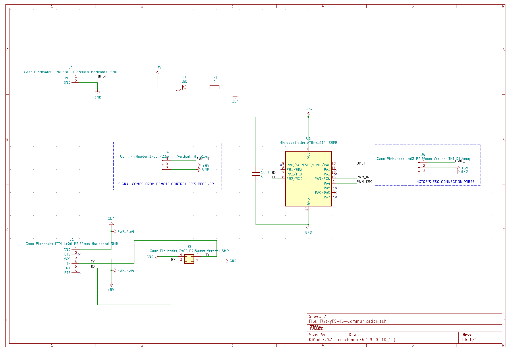
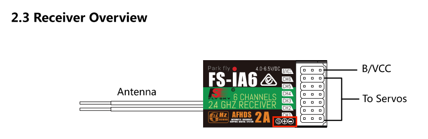
- In Output Devices week I understood how to work with Brushless motor and ESC (Electronic Speed Controller). Now is the time to go even further and closer to the final project. For that is necessary add two components - Remote controller(RC) and compatible Receiver with Double Antenna. I work with these models - FLYSKY FS-I6 and FS-IA6. Look at Manual here.
MY OWN ELECTRONIC DESIGN | KICAD SOFTWARE
Official site for download KiCad here.
- Electronics components what is necessary:
Some notes that are good to know:
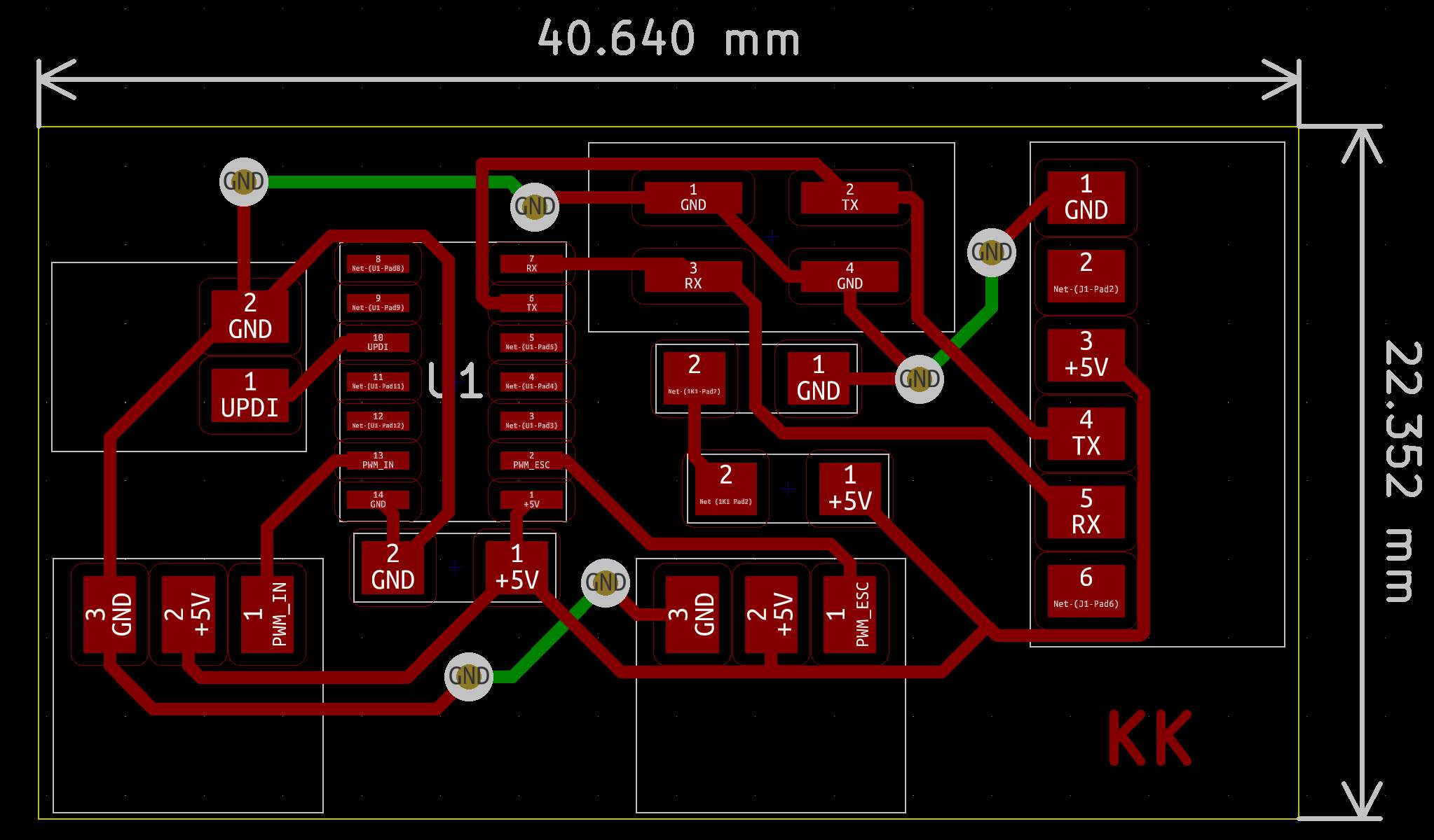
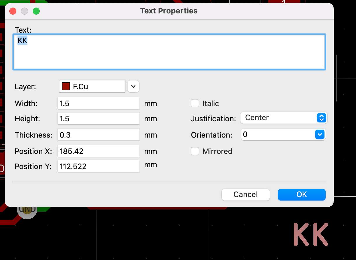
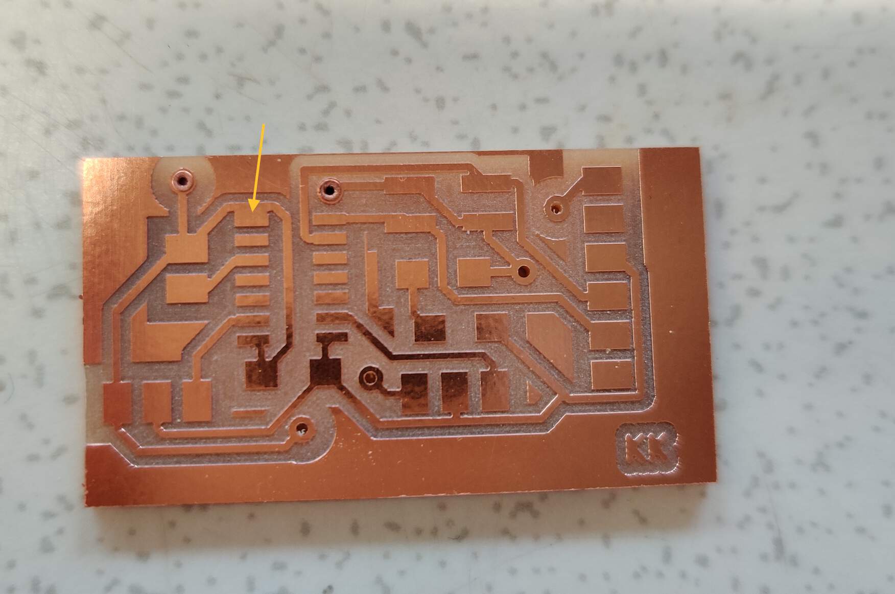
THE RESULT OF ELECTRONIC DESIGN & MILLING & SOLDERING PROCESSES
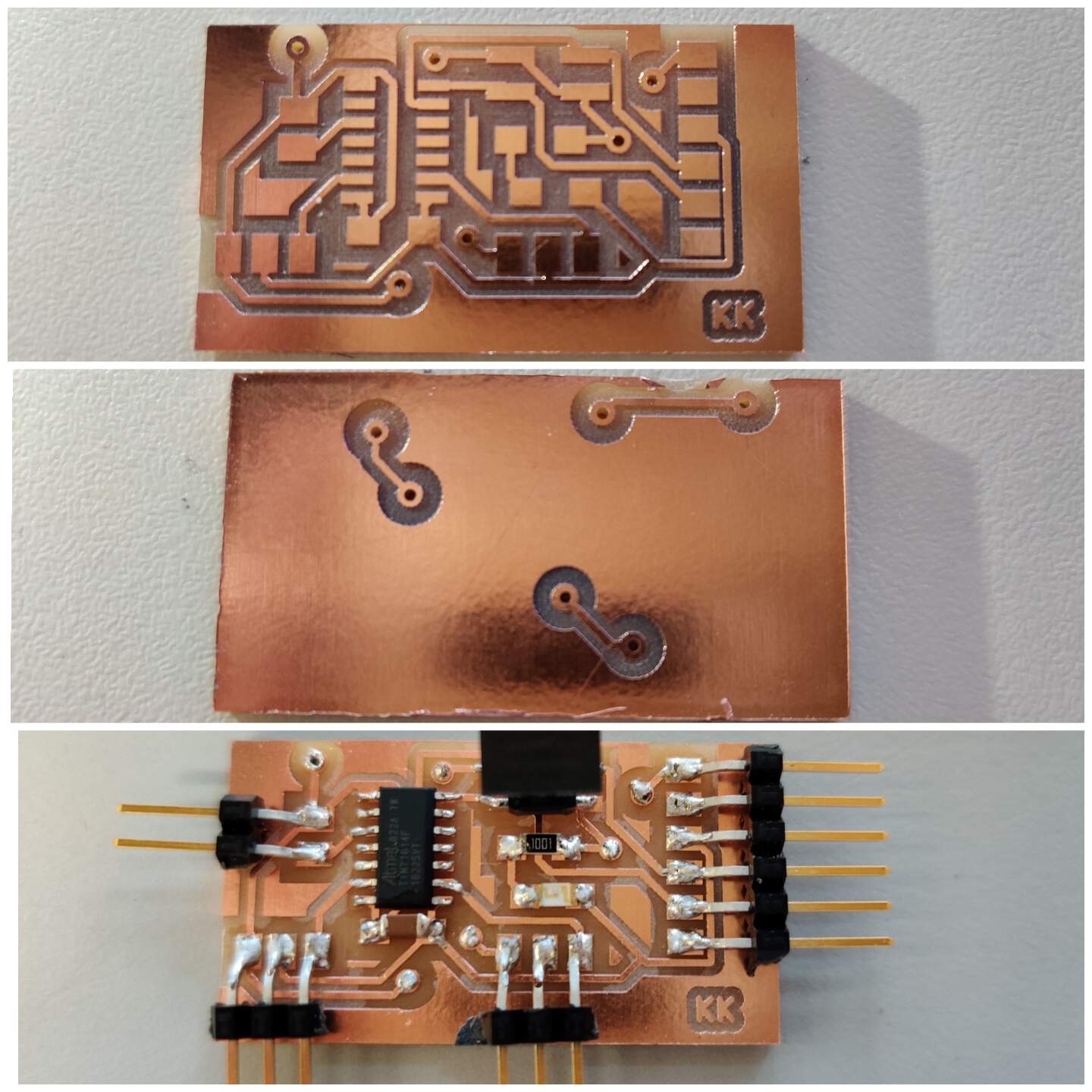
- When I was soldering I recognized one mistake - one of the chip pads was connected together with one of GND traces. That's interesting because in design all is right, maybe in CopperCam software that I used for preparing files for the milling process after toolpaths generation I didn't see red lines which means that it is possible that something can happen wrong. But I am so lucky! This pad is with empty functionality so I didn't do anything to fix this mistake but if it has necessary - then I will use a knife to cut the connection.
TX & RX COMMUNICATION BETWEEN RC AND RECEIVER (THROUGH ANTENNAS)
- Always you switch ON RC be sure that all switches in their up position and the throttle - lower position. I don't think that anybody wants motors to start to move without control. To understand it with alert signal I did it when it is ON ❗ but please do it before you switch ON it!
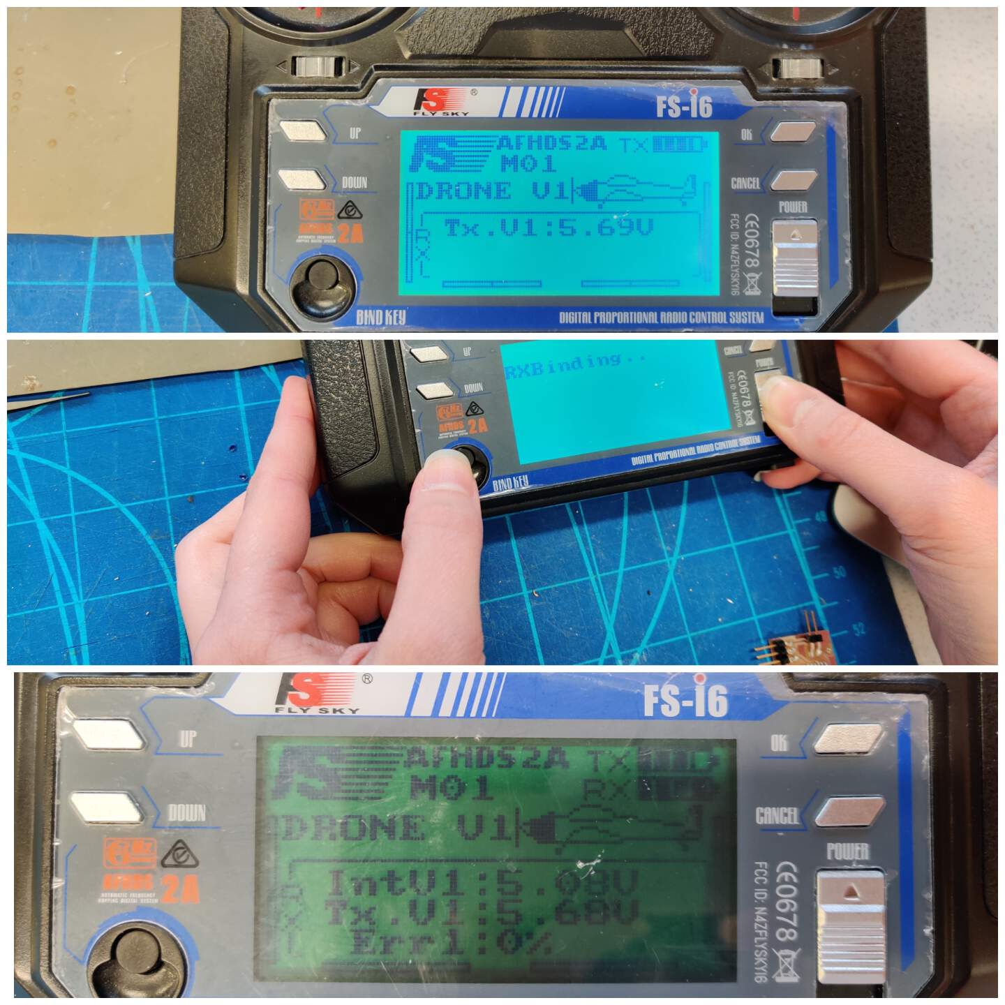
- Only once is necessary to connect RC and Receiver with the Bind key button. It means that you want to connect directly RC with this Receiver. The video below is a good explanation of this process. In my pictures you can see (1) before (only TX level) - (2) in progress- (3) connection successful (TX, RX levels are seen).
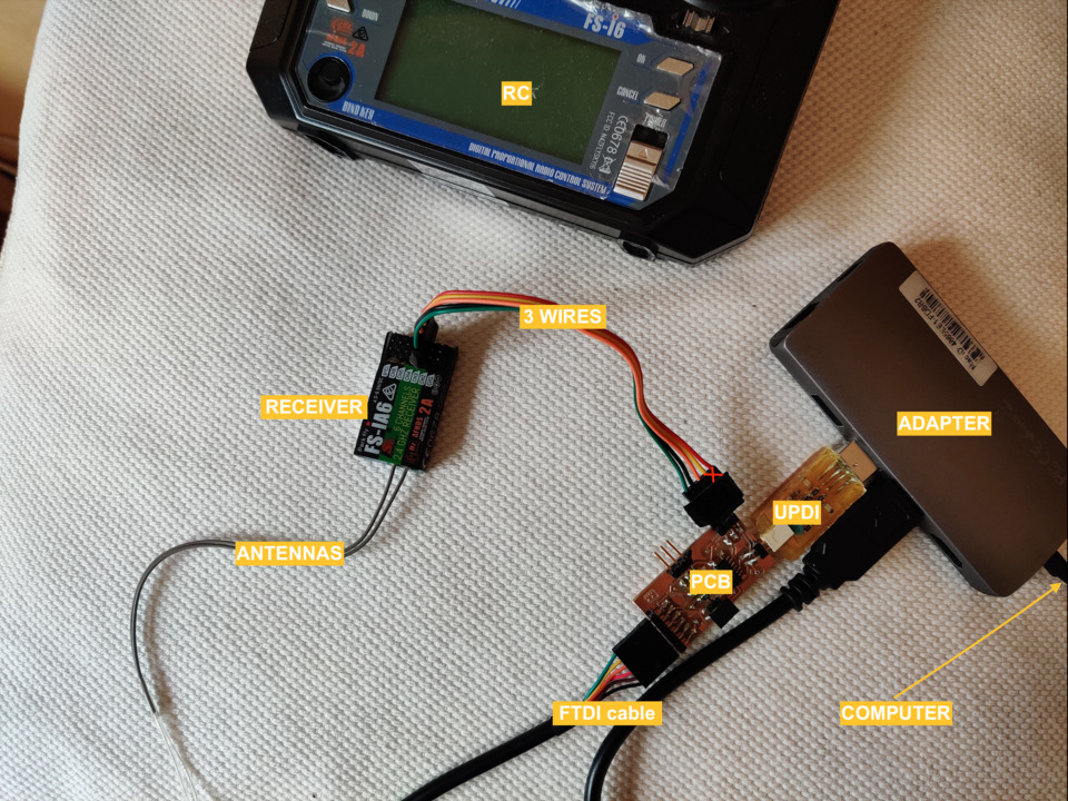
- Now it's time to connect everything together! Just a note - I used 5 wires in the connection, because they were all connected in one header, but for this task 3 wires are enough.
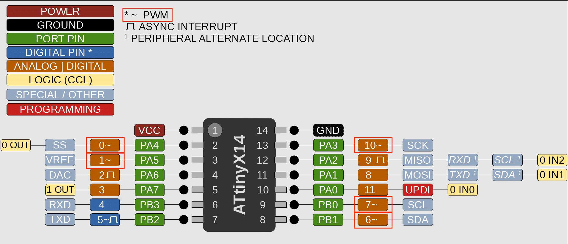
- Then I started creating a program, although the number of program lines is small and now it looks simple, but I spent a lot of time imagining and understanding these things. For Receiver (PWM_IN) I chose Attiny 1614 chip's pin PA3 that in Arduino equals - number 10 (look at SpenceKonde picture above). Function pulseIn() I used to give a pulse to the Receiver start to recognizing incoming values from remote contoller. The pulseIn () function reads the pulse at the corresponding pin (in my case No. 10). It can only read two states - LOW or HIGH. One of these states also forms one pulseIn () function parameter. The second parameter is a pin number. I have specified HIGH, which means that the program is waiting for the transition from LOW to HIGH, which means that an impulse will come in. This function reads and returns the incoming pulse length in microseconds. It does not need to be specifically described in the parameter - it is provided by function by default. This function is required when working with PWM (pulse width modulation). You can read more about PWM in the week Output Devices. If the pulseIn () function does not receive a pulse (no user acts), it returns 0 if no full pulse was received. When I acted on the remote controller values by moving it, the values returned to the pulseIn () function were returned to the display.
        double channel;
            void setup() {
                pinMode(10, INPUT);
                Serial.begin(115200);
                Serial.println("Initializing...");
                delay(1000);
            }
            void loop() {
                channel = pulseIn(10, HIGH);
                Serial.println(channel);
                delay(1000);
            }
This video not included in GIT, because size of it is more than allows also after video optimization.
COMMUNICATION BETWEEN RC AND RECEIVER TO PCB AND ESC
- Then I combined the knowledge of the previous week and the new ones of this week to put it all together and create one coherent program.
        #include < Servo.h >
        #define IN_PIN 10
        #define ESC_PIN 0
        int pwmIn;
        Servo esc;

        void setup() {
            pinMode(IN_PIN, INPUT); // Read the channel signal from the receiver
            esc.attach(ESC_PIN,900,2100); // Pin, min pulse width, max pulse width in microseconds
            //Usually for ESC [1000;2000] microseconds but for drones - lower and higher could help work smoothly.
            //I read it somewhere but forget this resource.
            Serial.begin(115200);
            Serial.println("Initializing...");
            delay(1000);

            while(1){ // equal with void loop but works faster
                pwmIn = pulseIn(IN_PIN, HIGH);
                Serial.print("Receiver: ");
                Serial.println(pwmIn); // outputs the incoming value from the receiver

                int motorSpeed = map(pwmIn, 977, 1956, 0, 180); // [977;1956] - min./max. values from RC and [0,180] - servo angles
                if (motorSpeed > 0){
                    esc.write(motorSpeed); // assigns an input value to the motor
                    Serial.print("Speed: ");
                    Serial.println(esc.read()); // then show the speed value (at this moment - only theoretically)
                }
            }
        }
- I turned off the power and went to instructor Kris for advice. He explained that this was due to an incorrectly set Current value. Now we set it to 0.04 amps. And then I realized that all the time I was focusing on voltage values, but I forgot that current is also important (quite logical!). Then we also understood why my efforts at home failed - we read what the current is for the power supply I use at home - 150 mA. And then I remembered that in last week's task, when I'm not using RC yet, but only experimenting with ESC and a brushless motor, I already found out that the minimum current was 0.04 amps and the maximum is 0.8 amps. To be sure I checked the converter that 0.8 amps is equivalent to 800 mA. Now it is clear to me why the motor only partially turned. Very good lesson!
"HERO SHOT" VIDEO - RESULT
This video not included in GIT, because size of it is more than allows also after video optimization.
WHAT NEXT?
- Very important conclusion - this remote controller(RC) and Receiver is exactly what I need for my final project. What next? Start to develop a flight controller PCB logic and design for four ESC and brushless motors.
GROUP ASSIGNMENT
- This week was to establish communication between the two boards, not using only own two boards, but one of them is from another member. Challenge No.1. in the documentation of the other member of the group find the correct week within which he developed the board (some had developed communicative board even before this week). Together with the group members during the experiments we tried to communicate with different boards and encountered various difficulties:
- 1. We used my board of this week and Wu Ruo-Xuan board with a built-in button to control my board brushless motor. Unsuccessfully - by pressing a button on the main board, it sends a value of "1" to the secondary board - the motor starts to rotate with a certain value X. The motor rotated, but did not seem to always respond accurately to the button signal, it still works in previous responded signal.
- 2. Then we tried my board of Input Devices week as a main and the same Wu Ruo-Xuan board as secondary to control LED light depend of fixed distance from the hall effect sensor between magnets. After long attempts we tried to upload my original program to individually without communication to make sure the hall effect sensor works. My board was broken.
- 3. Then we tried again Wu Ruo-Xuan board as the main and Solomon board as the second, which turns on the LED when the button signal is sent. Solomon had used a non-standard solution in his individual work - to use TX, RX pins not as default, but specific other pins. He also used Arduino SoftwareSerial library in his individual work code, and as we later read in the Arduino documentation board as the second, "If using multiple software serial ports, only one can receive data at a time." We didn't find a solution and tried something else, but later Ranjit told us the solution, that we could implement this library as well, only then we need to include the delay () function, which will force a delay in signal transmission.
- 4. And finally - we used my Electronics Design week developed board as the main and Wu Ruo-Xuan DC motor driver board as the secondary. The idea - while nothing happens, the red LED is on when the button is pressed, the blue LED turns on and the signal is sent to the second board - the motor starts rotating. The motor rotates as long as the button is pressed. We used the Serial port for communication and the sending values were bytes. The program logic author is Wu Ruo-Xuan, which we adapted from his individual work (more code explanations are available in his documentation).