PCB DESIGN MADE WITH KICAD SOFTWARE
VERSION 1.0. FAILED
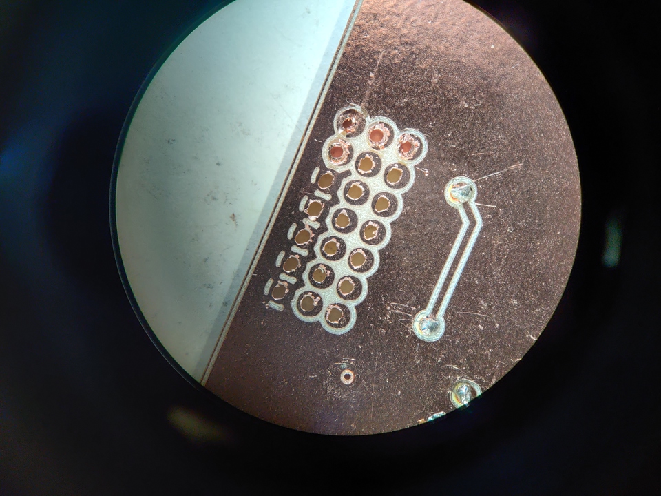
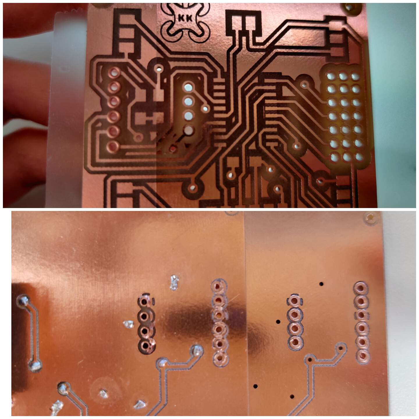
- For my double side PCB I used 43 through hole rivets. I used 43 hole rivets for my double sided PCB. I hadn't used it before! Mistakes why it failed - CopperCam's Drilling Depth software was set to 1.8mm (2mm more than copper clad thickness), but as a result the holes on the other side were not completely cut. I manually made the holes to the end with a screwdriver, but it was a very bad idea, because the holes on the other side were not circular, but notched, it later affected the process of pressing the rivets - on the other side more copper layer was cracked than necessary. As a result, a forbidden connection was formed between the rivets and copper.
VERSION 1.1. FAILED
- In the second attempt, I set the drilling thickness to 2.4 mm, but so much probably not necessary. As a result - in the holes can shine the sun, wonderful! Compared to the first attempt - this is much better, but ..
- After soldering, the program failed to upload via UPDI, Arduino said "UPDI not recognized". During the continuity test, I concluded that the capacitor connection of the microcontroller is unstable. It was not a good idea all GND connect the back side of PCB - capacitor, which is required for the microcontroller is need make a short and direct connection.
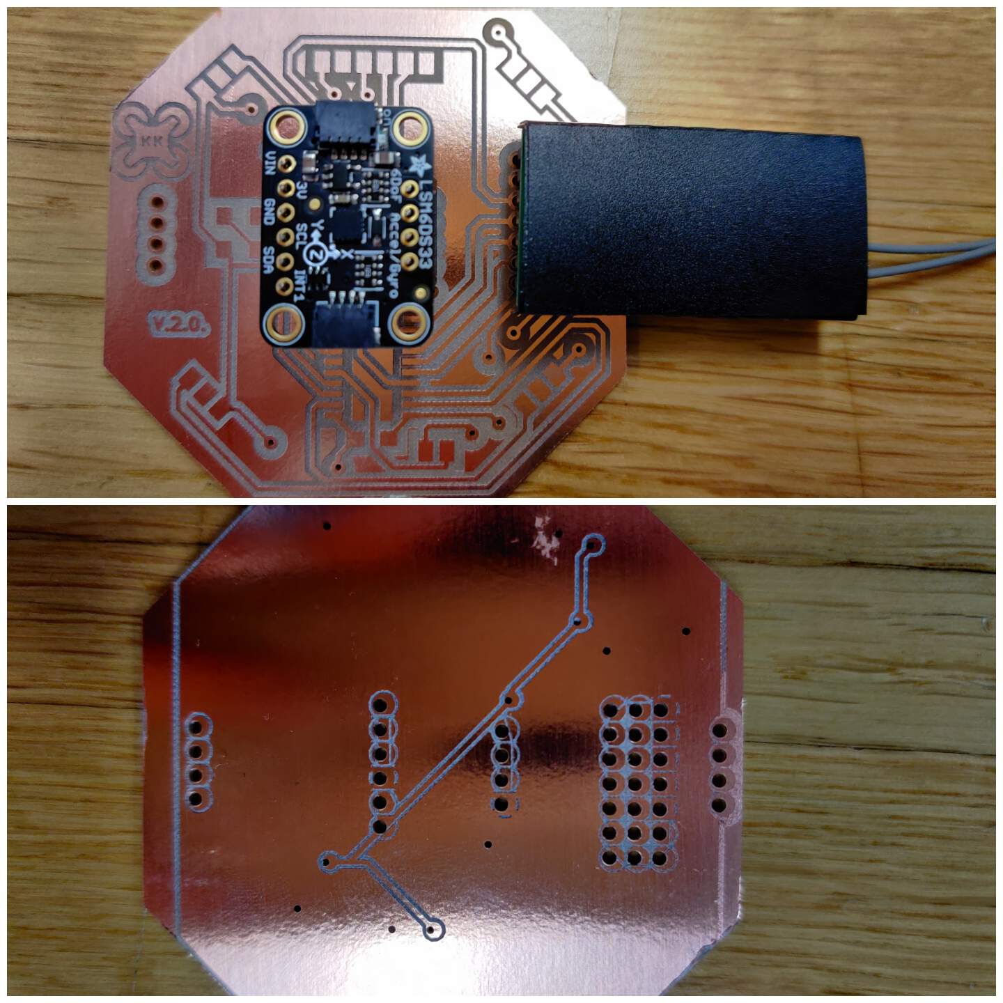
VERSION 2.0 FAILED
- Since I have to make a new PCB, my instructor Kris also advised me to place the accelerometer & gyroscope module directly in the center of the PCB, because later during programming, the mismatch [0; 0] can complicate my life. The design has also been improved, with ESC pins put at a 45-degree angle to improve the visual effect.
- But why did this attempt also fail? Due to asymmetry. I'm not very strong in geometry, so the corners of the plate were not accurate. How did it hurt me? It is a double side PCB - it was difficult to insert the PCB in exactly the same place as the front side when milling and inserting the back side of the PCB.
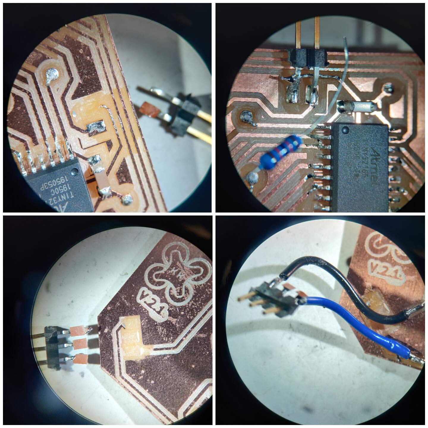
VERSION 2.1. WORKS BUT STILL NOT GOOD
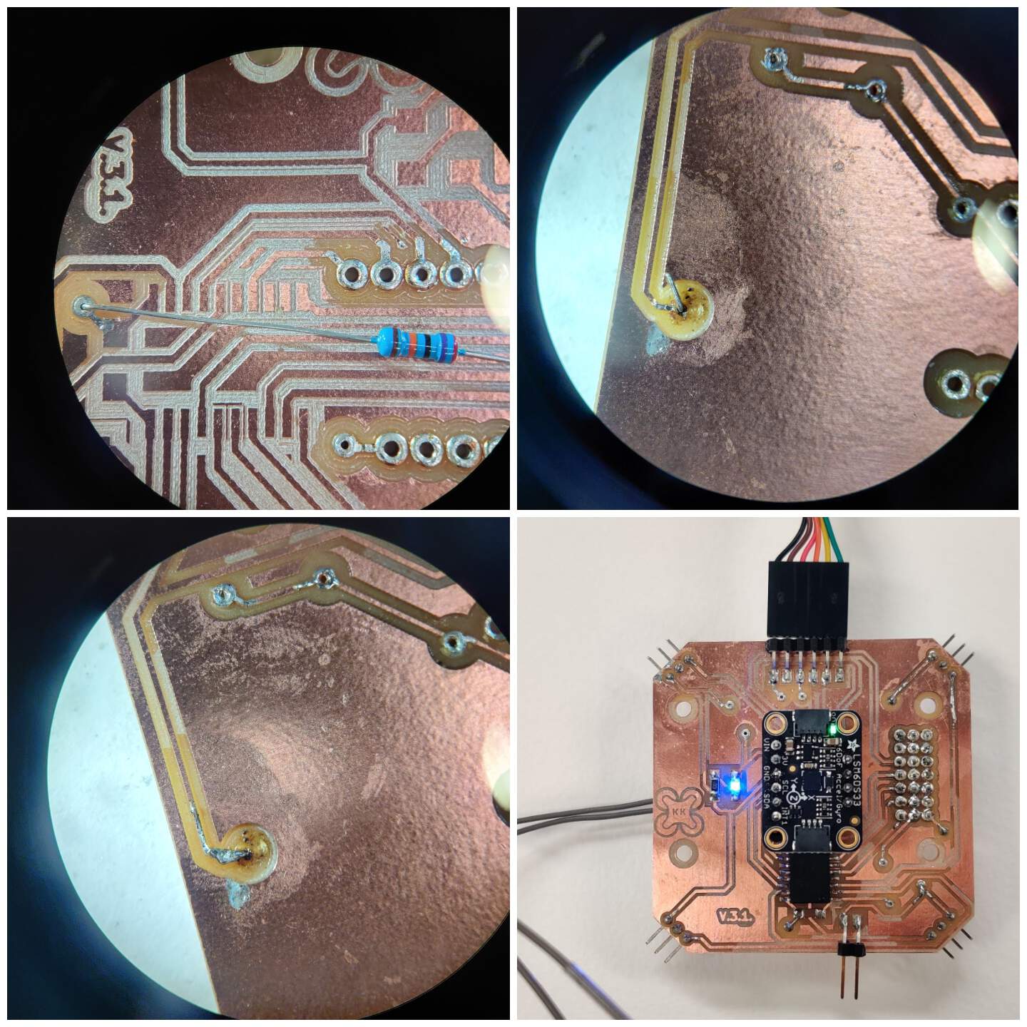
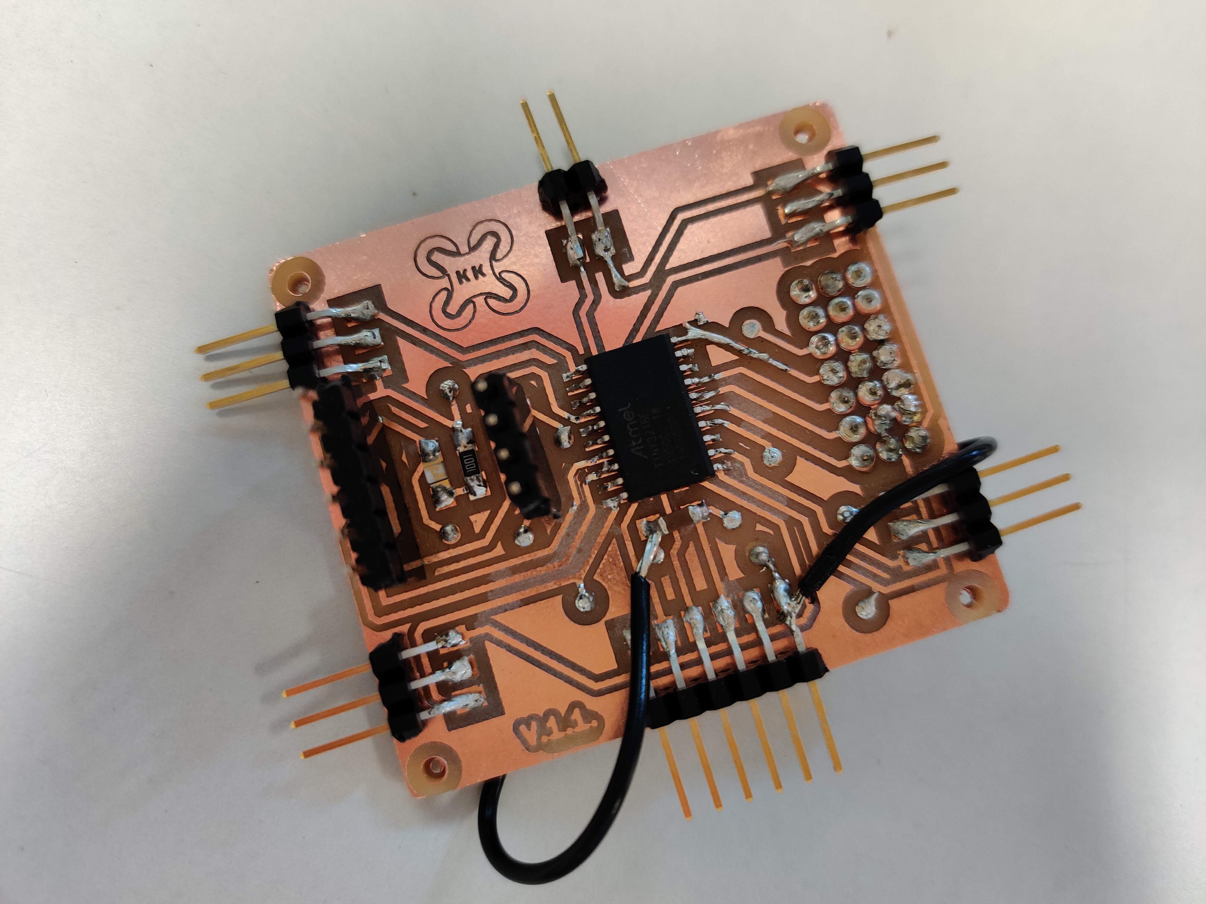
- I corrected the asymmetry errors and then faced other challenges in the soldering process - as UPDI had soldered one pin at a slightly oblique angle I tried with force to return it to a right angle - as a result it broke, tearing off the copper layer as well. The instructor Kris showed me a trick - to take another type of resistor (with metal wires on the sides) and solder it using it as a bridge. The process was full of challenges - I felt like a doctor who works in the surgery. But it succeeded. The pleasure was short-lived, later the PCB fell on the floor and one of the ESC ports broke with the whole copper layer. As a temporary option (to finally get to programming) I used jumper wires.
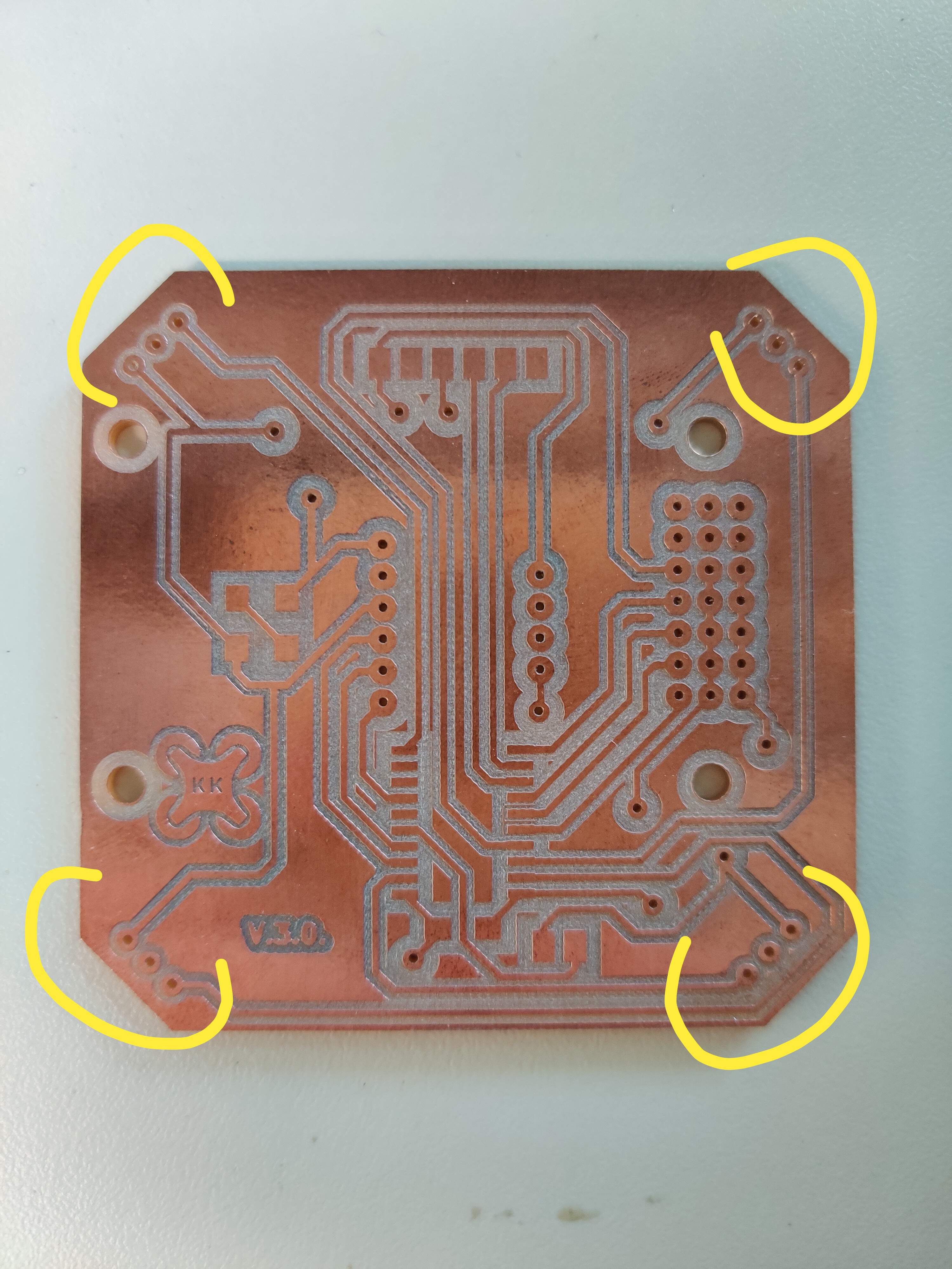
VERSION 3.0. - FATIGUE FAULT
- After the programming process was successful and I was convinced that the PCB logic was working I made changes in the schematic part in KiCad software, choosing more robust ESC connections - through holes with double side solder. Due to fatigue, in the CopperCam software I forget to specify the drilling tool 1 mm in the settings and therefore the ESC ports were cut to a smaller size - this does not suit me. Have to mill again!
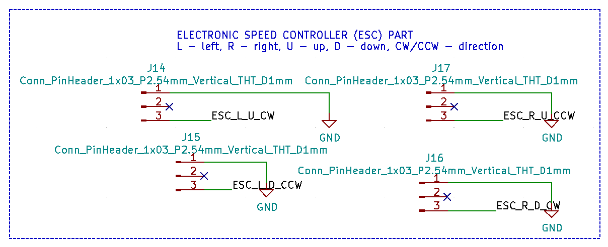
FINAL SCHEMATIC OF FLIGHT CONTROLLER PCB
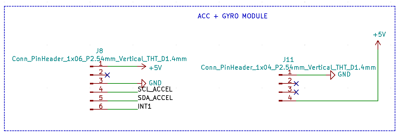
- Compared to the ESC I used in Output Devices week, which had three connections, these ESCs I will use in the drone have two wires (but still three pins) - white - SIGNAL, black - GND. In the datasheet I found out that for data exchange I need I2C serial - SDA and SCL and programming INT1.
- ❗Information update - after the final project presentation and documentation this section I saw the risk - I have not activated SDO / CS as pins, but in the data sheet they are listed as interface serial data output.
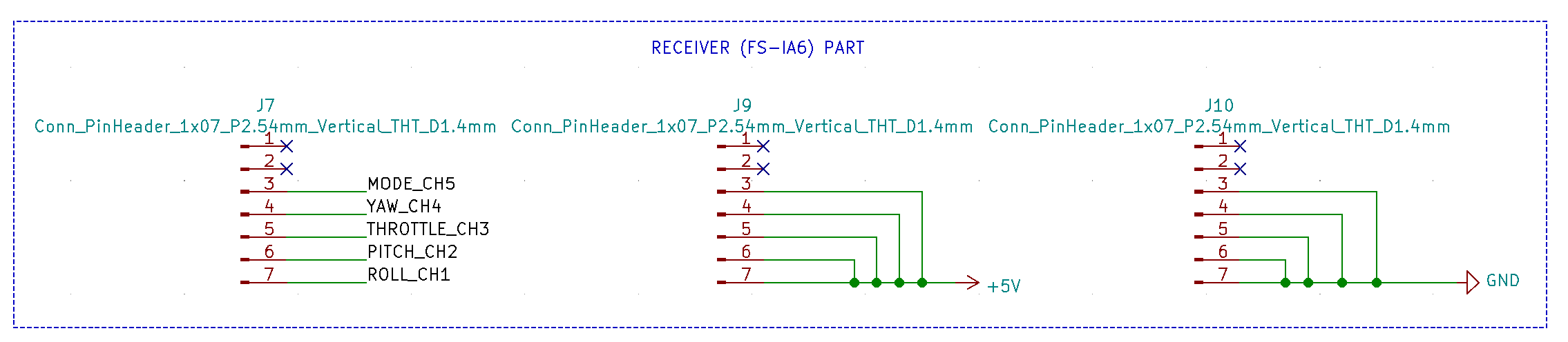
- How to know the sequence of receiver pins, look for Networking and Communications week.
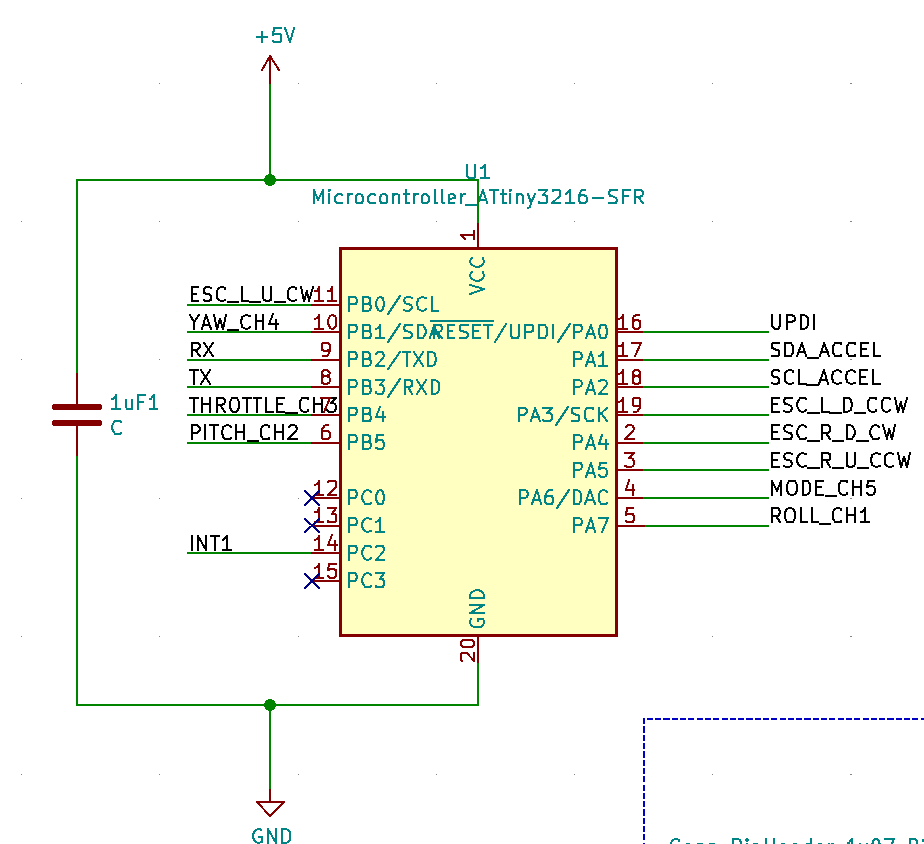
- I used a microcontroller ATtiny 3216. The layout of all pins is according to the SpenceKonde scheme. It is important to remember that a capacitor is needed and should be placed as close as possible to the microcontroller when designing.
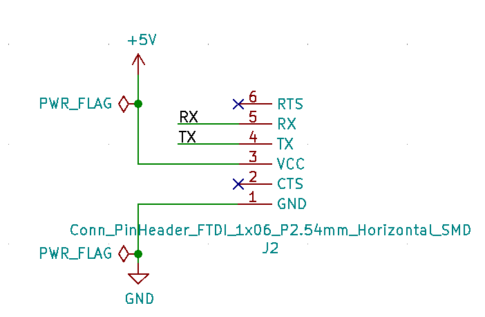
- In the programming process, I used this to see real-time values on the Arduino serial monitor, but later, when integrated with the power supply PCB TX, RX pins will not be used, but only VCC and GND pins to receive power from the second PCB.
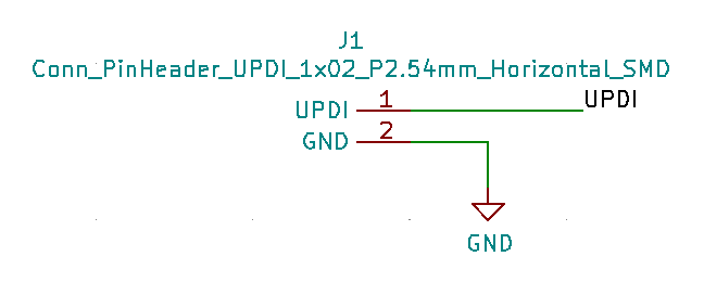
- UPDI is required to upload the program code to this PCB. This microcontroller is not directly programmable on the Arduino, for that I used the UPDI which I made in Electronics Production week to transfer the program to this microcontroller PCB.
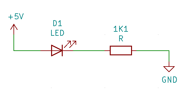
- This is optional, but usually very useful to add a LED that will allow you to easily determine if the power supply is coming.
VERSION 3.1. SUCCESS
- Unbelievable - successful! Of course, not without challenges, in some places the rivets edging tore to make sure that after soldering the connection between front and back side work - I used a previously learned trick - pulled through resistor metal wire of the both sides.