MILLING MACHINE "DGSHAPE SRM-20"(GROUP ASSIGNMENT PART)
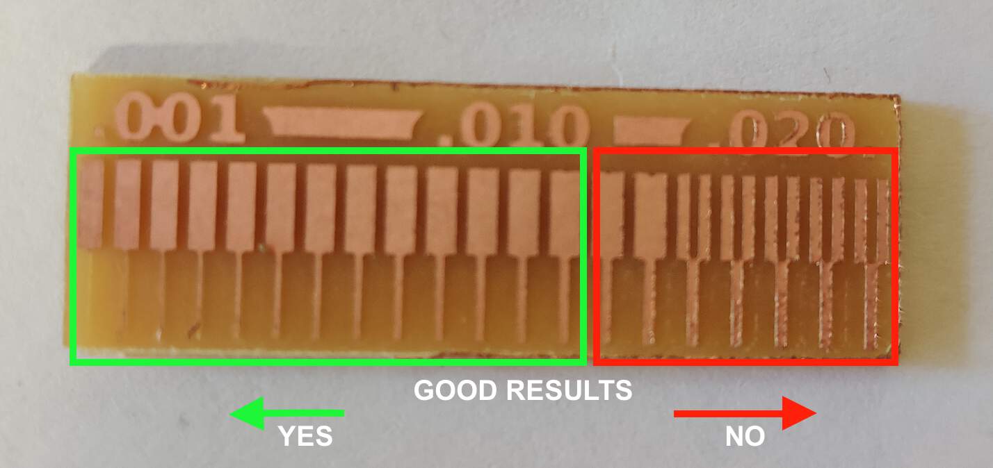
- To demonstrate the accuracy of our laboratory milling machine "DGSHAPE SRM-20", we had to perform milling. How thin a line can it mill before it becomes too thin and what is the thinnest line it can mill between two close feet. We used a ready-made design from Fab Academy - traces and outline. We used 0.4 mm tool diameter and 0.10 mm cut depth.
STEP: MILLING PRECISION TEST TO CHARACTERIZE MACHINE POSSIBILITIES
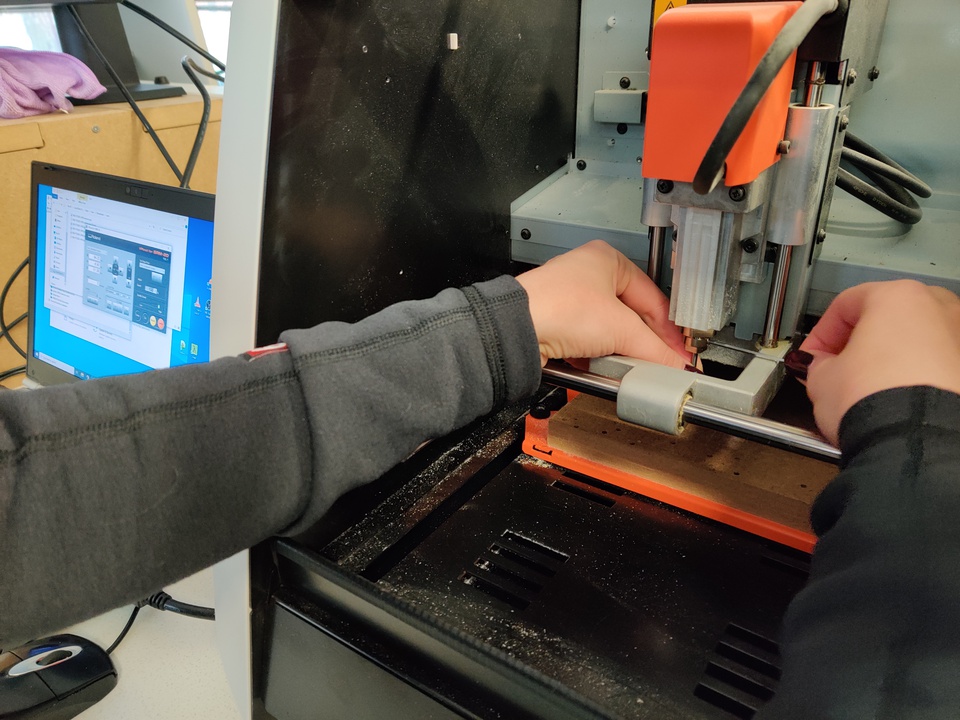
- This is a three-axis machine like a laser cutter or vinyl cutter. Machine has moving head so which moves along the x-axis, the y-axis and then there's the spindle which basically is a motor. With some the set screw and a place where you can insert the collet and in the collet you can install it and then the tool which moves in z-axis direction. Maximal work area aprox. 20 cm (X) by 15 cm (Y) by 6 cm (Z).
- Set of tool that you can use for PCB milling - 3 different milling tools.
First is 0.8 mm which you can use for cutting and drilling holes. In this case you need to choose 2 mm/s speed.
Second is 0.3 mm which you can use for extra small parts. In this case you need to choose 1 mm/s speed.
Third is 0.4 mm. In this case you need to choose 1.5 mm/s speed.
❗ Be careful, this tools are fragile and when you want change the tools make sure that you hold it with your two fingers. -
I try install 0.3 mm milling tool, for that I also need Allen key in order to set in place.
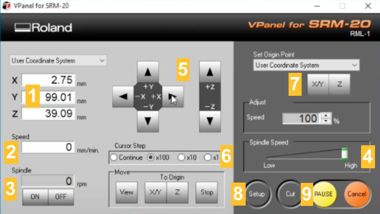
❗ Why is it called "Allen"? The terms "Allen wrench" and "Allen key" are derived from the Allen brand name and refer to the generic product category "hex keys". W.G. Allen filed the first related patent in 1909 for its recessed hex-driven safety screws, a safety improvement over fasteners which protruded from machinery. (Wikipedia) - This software let's you control the machine.
- (1) On the left side you can see current x,y,z coordinates. (2)This is a movement speed kind of feed rate.
(3) And below you can see spindle speed per minute. (4) So you don't have any speed controls except spindle speed slider
that goes from low to high. Usually you want it to be high for best cutting performance. (5) There are arrow keys which allow you to
move positions.
❗ Be careful with Z-axis when you use arrow keys. You need to make sure that you don't get too close to the actual material or the surface of the working area. Whenever you're getting closer to some limits where you have the potentiality of breaking the tool (6) change Cursor Step to x100 that means that it's gonna move 1 mm at a time, so basically one step of the machine equals 100 of mm. (7) In order to set origin you will need to use these buttons. For set X/Y axes origin there is only one button, click YES. For the Z-axis there is a separate button. So you cannot set X and Y separately. - (8) Before you mill you want to make sure that the setup of the control software is correct. So for milling PCB if your'e doing it with mods, then in settings you need choose Command Set "RML1-1"
- (9) When you are ready, click Cut button. It's not gonna start to cut immediately it's because you need to specify what you wanna cut. If there are previous jobs delete them. Find and upload your file and click on the Output button.
- ❗ After that it's going to activate the spindle, but at the first just to be sure - reduce the speed, for example, too 20%, so you want to make sure that it starts cutting correctly. If you see that it goes forward nicely, then you can gradually increase the speed until 100%.
- This is a circuit board material, industrial name of it is a copper covered clad, which is basically a sheet of a layer of copper. Top of a material is called FR1. FR stands for fire retardant so the FR1 is the least toxic but also the least fire retardant wo when we mill it, then there's going to be dust and if it happen that the dust particles get outside the machine then it's not that bad, but if you would be milling FR4 which is more like the industrial - you definitely don't want to breathe that.
- For the simple boards you need to select the one that is covered from one side. Then you need to use double sided tape in order to attach it to the surface. After that good idea is use a piece of cloth to make sure that it sticks very well on the surface.
STEP 1 : HOW TO USE THIS MACHINE TO MILL CIRCUIT BOARD?
STEP 2 : SOFTWARE "VPANEL FOR SRM20"
STEP 3 : MATERIAL SHEET
MILLING MACHINE "ROLAND MDX-40" (INDIVIDUAL ASSIGNMENT PART)
STEP 1 : TRACES
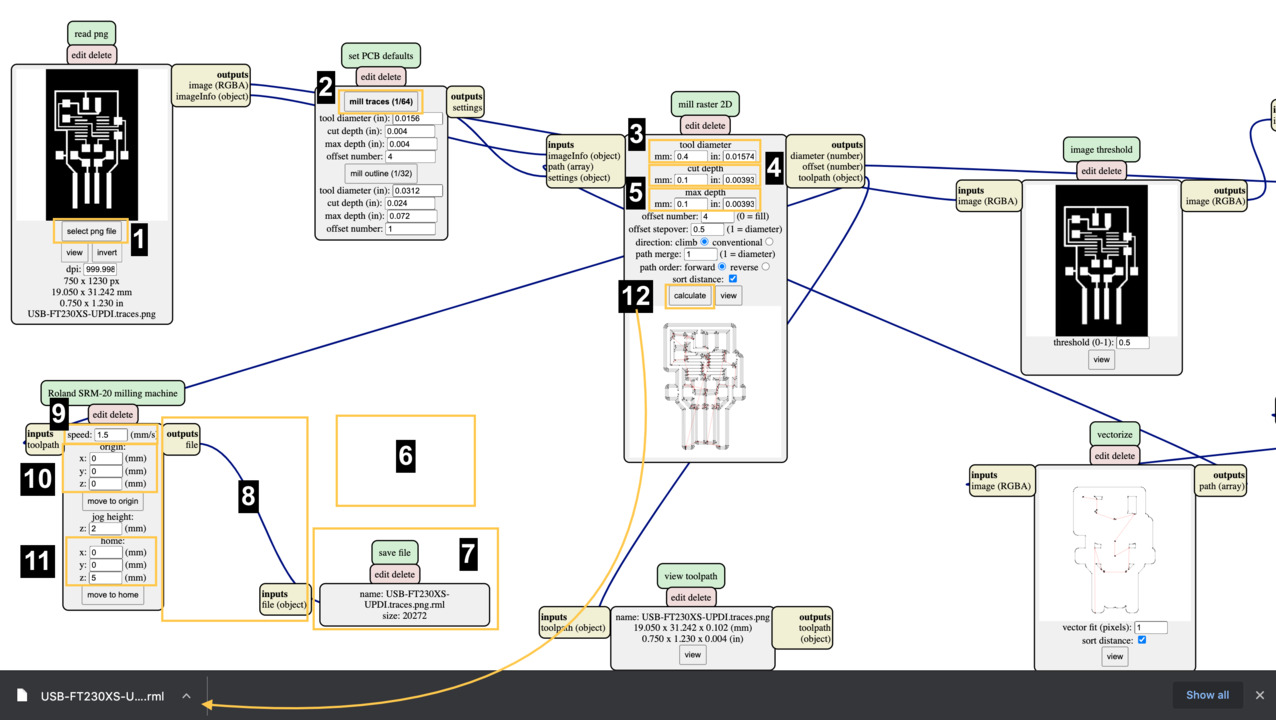
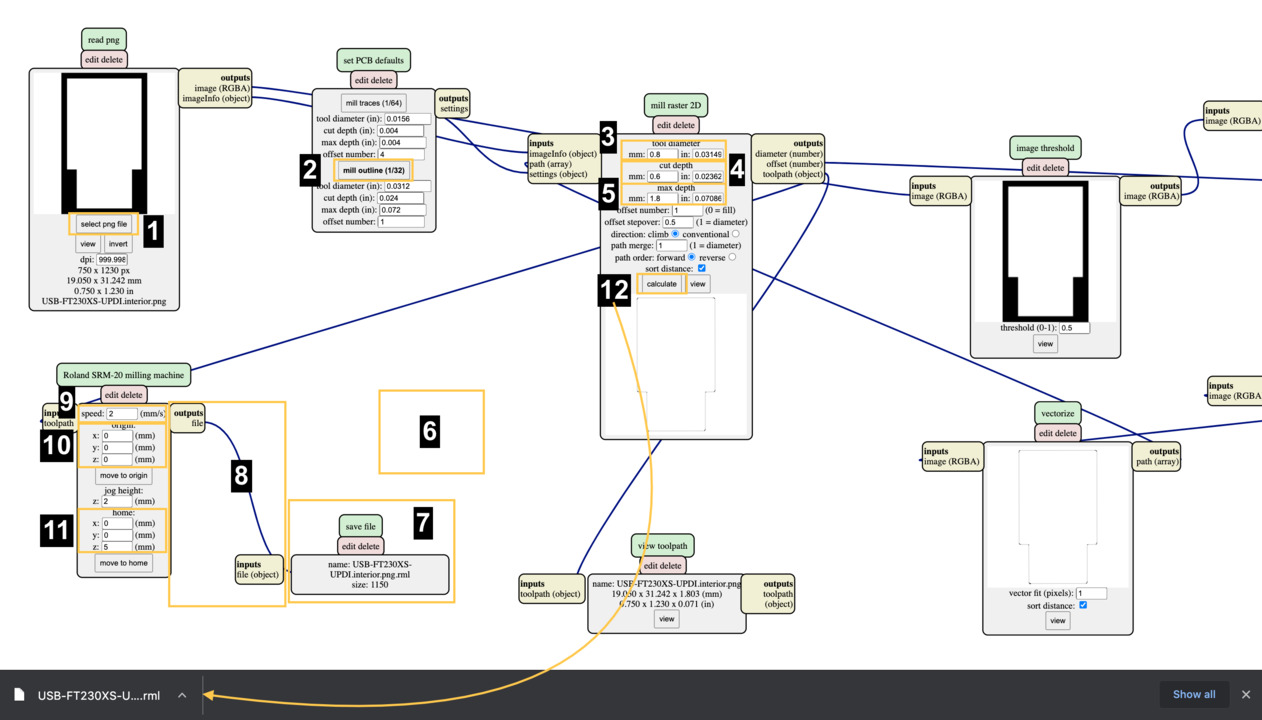
- Open the mods.cba.mit.edu on the Internet. Right click, Open programs, open server program and despite the fact that I use MDX-40 I can choose from menu Roland - SRM-20 PCB png (settings are the same).
- (1) Select png file - I start with traces picture.
- (2) In set PCB defaults box click mill traces (1/64).
- (3) In mill raster 2D box type - tool diameter 0.4 mm
- (4) Cut depth 0.1 mm
- (5) Max depth 0.1 mm
- (6) Delete WebSocket device box.
- (7) Click Right click, choose modules Open server module, file - save.
- (8) Draw line from outputs - file to inputs - file (object)
- (9) In Roland SRM-20 milling machine box type speed 1.5 mm/s
❗ Don't forget - in this case it doesn't matter that I use MDX-40, but name of box is SRM-20. - (10) Origin x:0; y:0; z:0
- (11) Home x:0; y:0; z:5.
- (12) Now in mill raster 2D box click calculate. RML file has been downloaded.
STEP 2 : INTERIOR
- Right click, Open programs, open server program and despite the fact that I use MDX-40 I can choose from menu Roland - SRM-20 PCB png (settings are the same).
- (1) Select png file - in this time I chose interior picture.
- (2) In set PCB defaults box click mill outline (1/32).
- (3) In mill raster 2D box type - tool diameter 0.8 mm
- (4) Cut depth 0.6 mm
- (5) Max depth 1.8 mm
- (6) Delete WebSocket device box.
- (7) Click Right click, choose modules Open server module, file - save.
- (8) Draw line from outputs - file to inputs - file (object)
- (9) In Roland SRM-20 milling machine box type speed 2 mm/s
❗ Don't forget - in this case it doesn't matter that I use MDX-40, but name of box is SRM-20. - (10) Origin x:0; y:0; z:0
- (11) Home x:0; y:0; z:5.
- (12) Now in mill raster 2D box click calculate. RML file has been downloaded.
STEP 3 : VPANEL
- Open software "VPANEL" to controll the machine. Mostly settings is the same like with SRM-20, difference - you can set Z-axis position with using sensor.
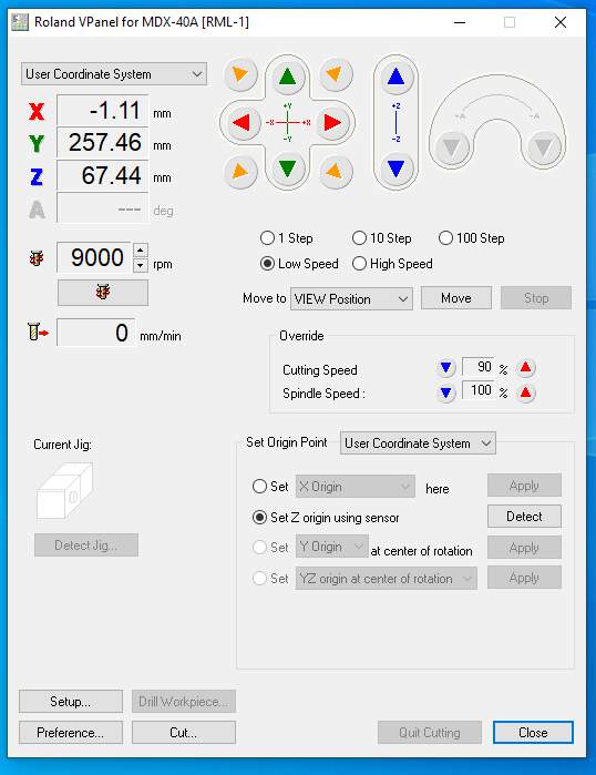
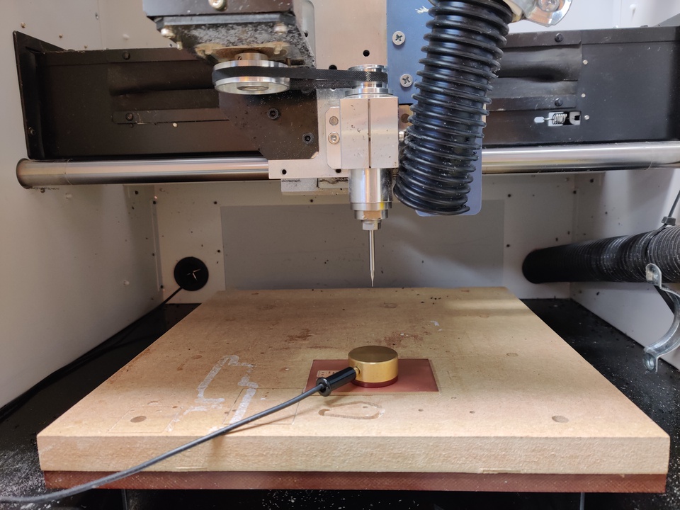
STEP 4 : SET Z-AXIS WITH SENSOR
- This is the sensor which basically can feel when the tool is touching it and software knows the thickness and depending when it's touched, software is setting the Z origin. Click on the radio button Set Z origin using sensor, choose detect and then - Continue. Now it's moving down. Click OK, when operation was finished. After that put sensor back in the place.
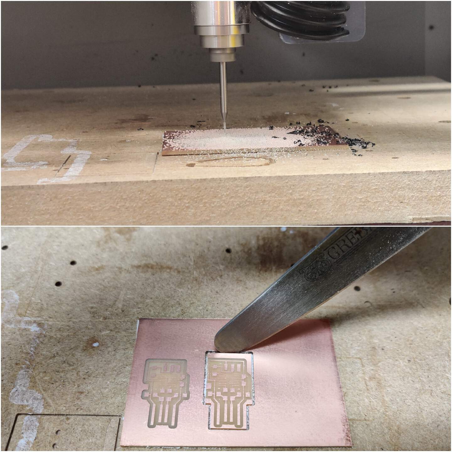
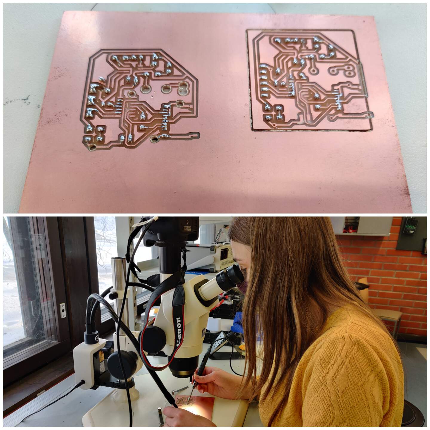
THIS IS PROCESS AND RESULT OF MACHINE
SOLDERING PCB
STEP 1 : EQUIPMENT
- Soldering iron, stand, tip cleaners, solder wire, tweezers, knife, flux pen, digital microscope and solder wick.
STEP 2 : PRACTICE
- First at all I just improve my skills in solder.
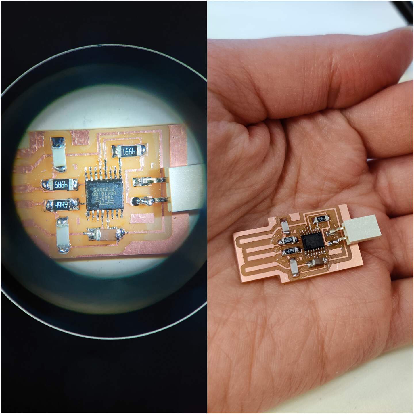
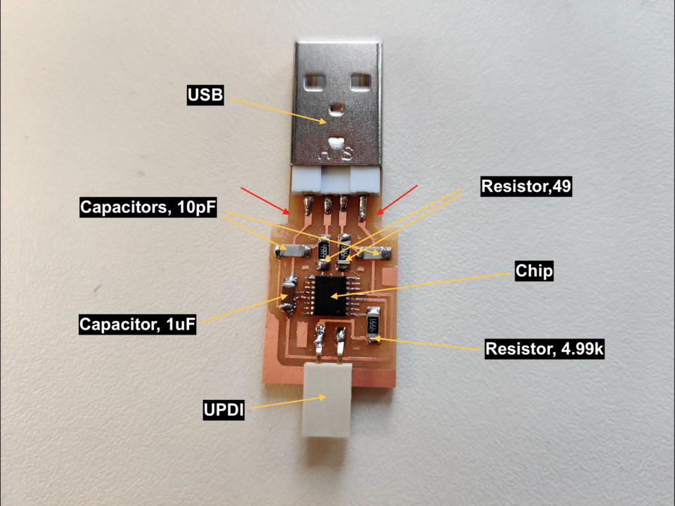
STEP 3 : COMPONENTS & SOLDERING
- If you added chip component, other parts seems like so easy!
- Below are the components what I used.
- ❗ Don't forget - before you check your PCB functionality remove copper part (see red arrows in picture).
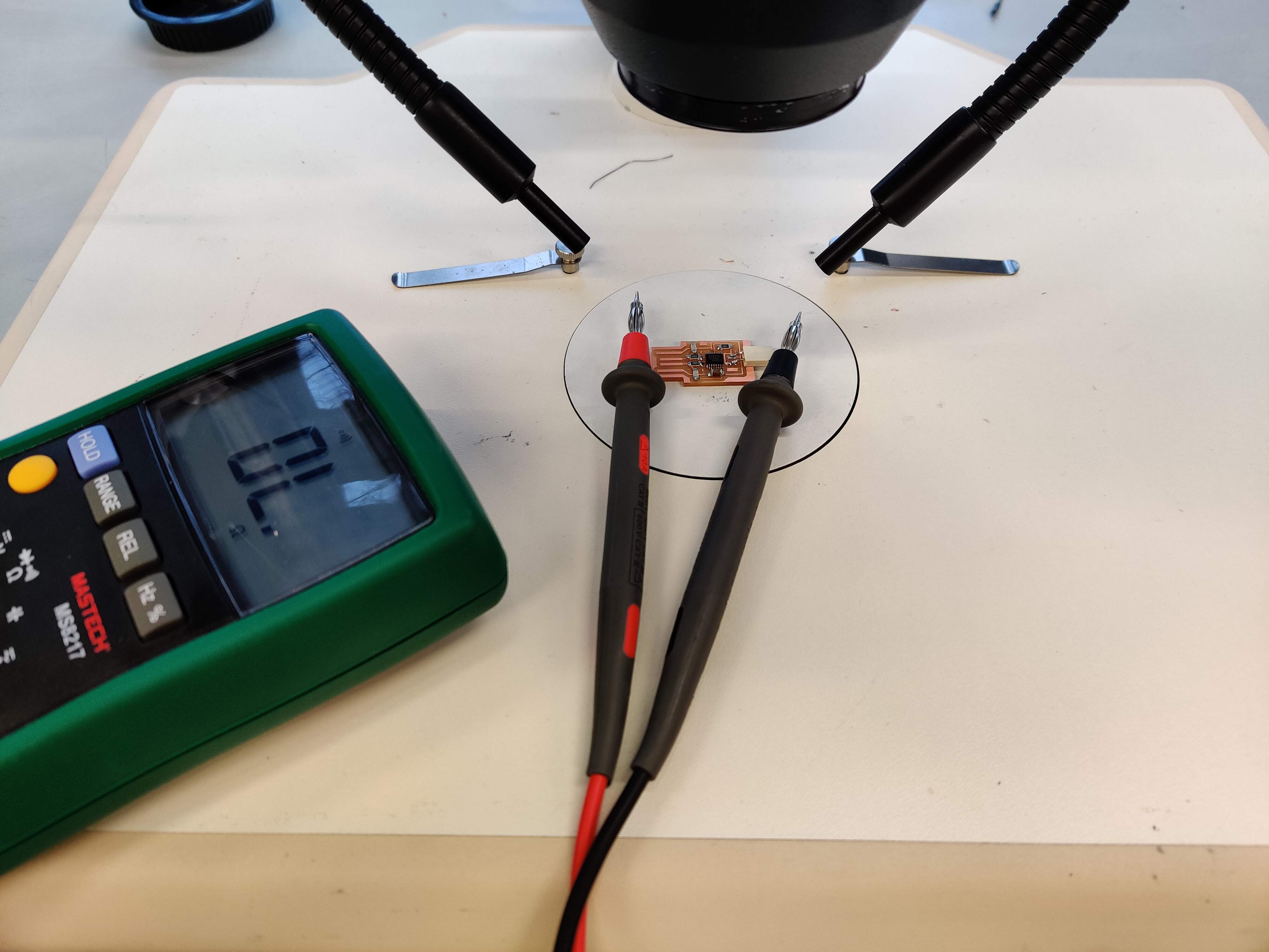
STEP 4 : CONTINUITY TEST
- For check how good I soldered I did continuity test. I looked at the scheme and tested the parts which need be connect. In this part most beautiful is when you can hear the signal - connection is!
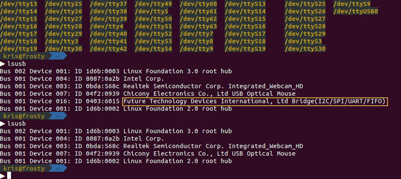
STEP 5 : FUNCTIONALITY
- In Kris computer we tried check functionality of my PCB. In terminal we wrote command line lsusb (on Linux OS). In screenshot you can see that first time we identify all connected devices to computer and one of them is my PCB, then we disconnect my PCB and now it doesn't recognize PCB.
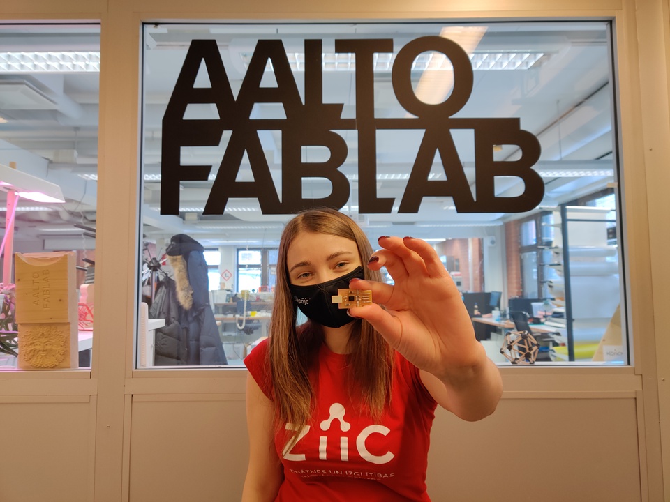
THIS IS A FINAL RESULT - HERO SHOT.
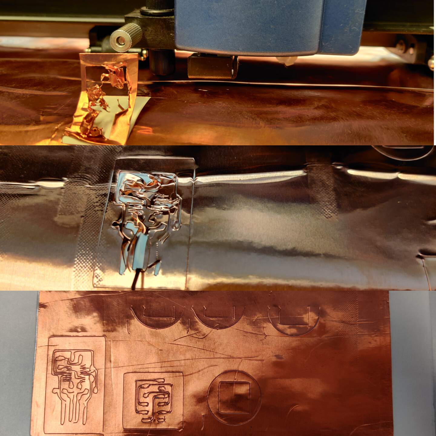
EXPERIMENTS WITH VINYL CUTTER
- Just for fun I tried make flexible PCB board with vinyl cutter. With Solomon we experimented with values and tested .. tested and again tested. First at all we changed speed from 5 to 3 mm/s - nooo, it doesn't work. Then we changed condition force to 80g and speed to 2 cm - nooo, again it doesn't work. Then we added tape layers, because we thought that maybe copper paper not so strength - result seems more better, but not so good. Then we changed the plotter blades which is suitable for 0.5 cardboard and hard materials. At the last experiment we also changed offset to 0.25 and force to 70. The best what we got you can see below in third picture's part, but we didn't get the best result.
CONCLUSION
- You need to have very healthy eyes or best quality microscope for soldering process. Soldering chip was most difficult thing that I have ever do in soldering. But I did it! Not with the first time - I couldn't do without solder wick.
- In soldering process after some fails I understood that I also forgot to fixed PCB board on the surface and this is reason why many times components moved out of place.
- I haven't decoded yet why from precise circuit scheme vinyl cutter distorted shapes.
- Practical things of this week will be usable for my job field - in future we could plan organize masterclass for oldest classes pupils. Masterclass how to make PCB board by myself and maybe add some light and button - a mini headlight would be very interesting for pupils. Kris showed an example - very nicely! But of course I understand that really usability is that you can add some components and after that programming it.
- Until now, I had only seen microcontrollers like the Arduino, Raspberry PI, but I had always paid attention to the components, but now when I look I can see what is at the bottom of it. I am not sure that I really understand role of all components, but this was the great week to understand how things build from the foundation.