PCB SCHEMATIC WITH KICAD SOFTWARE
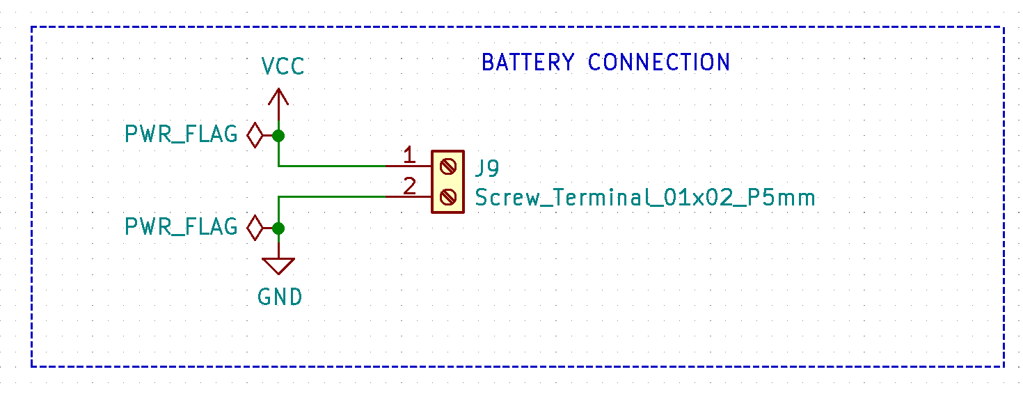
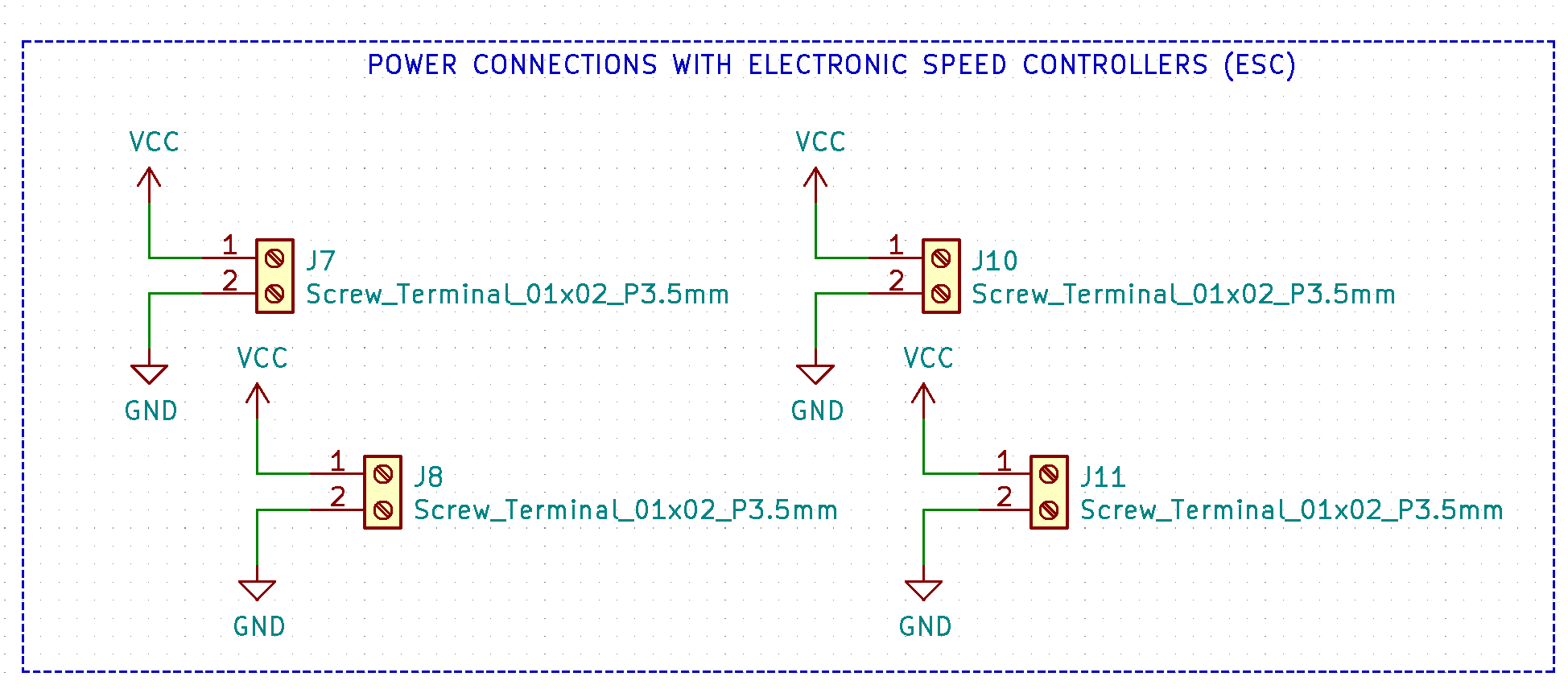
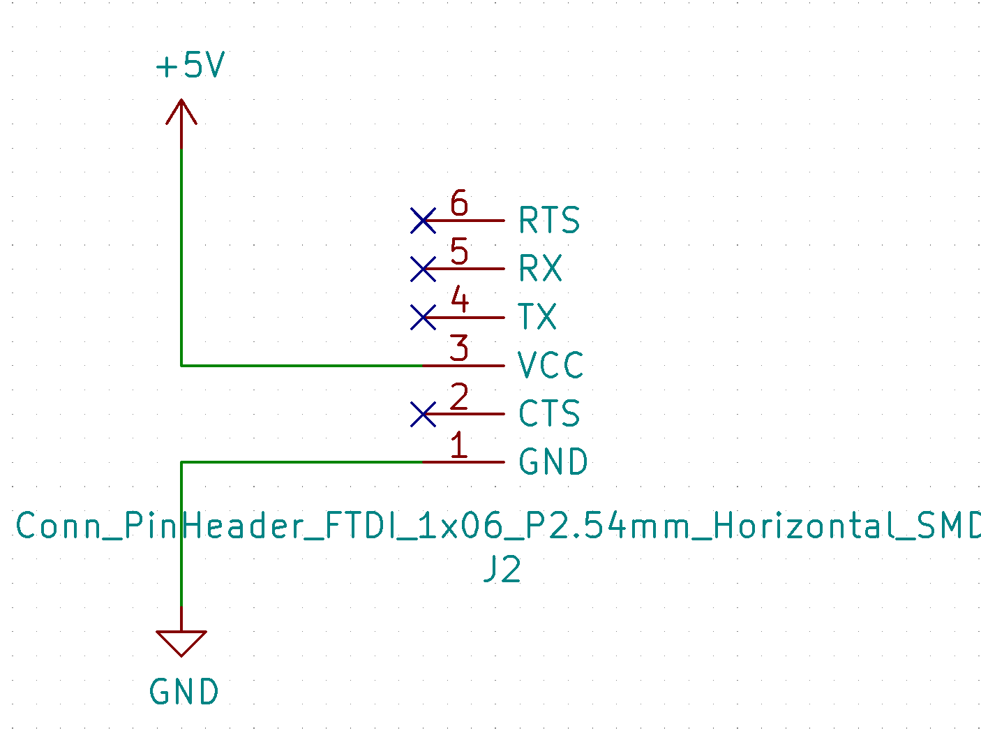
- Screw terminal (5mm pitch size) electronic component represents the GND and PWR ports of the battery holder. The PWR_FLAG element is used because it will be the actual power input. But four screw terminals (3.5mm pitch size) are provided for four electronic speed controllers (ESC) - for each motor.
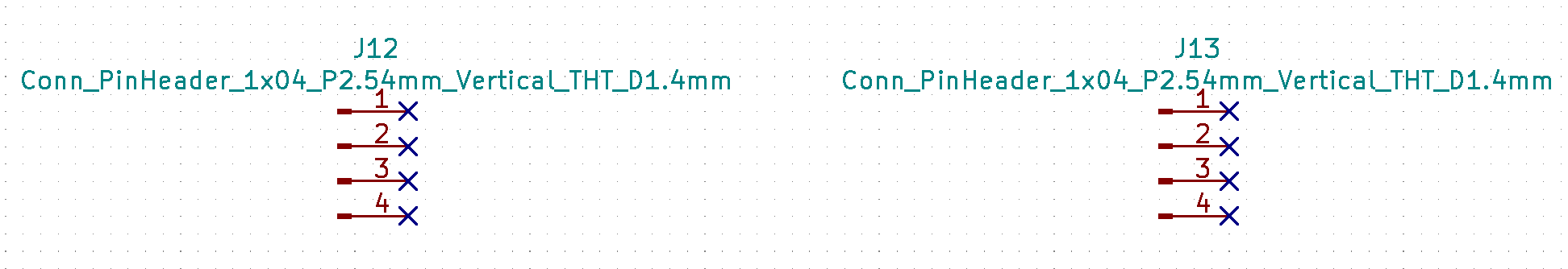
- Initially, I planned these as a connection to the flight controller PCB, but later after the changes in the frame design, this lost relevance. In my original files they are still there, because fortunately I made the power board only once (V.1.0.).
- In the Fab kicad library, this component is usually used for an FTDI connection, in my case the power supply PCB does not have programming functionality, but this component still is important because I will use it to connect to the flight controller PCB to provide power from battery which will be connected with power supply PCB.
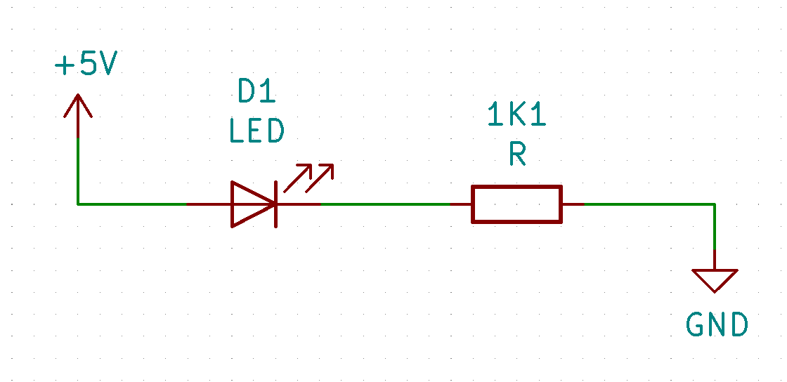
- This is optional, but usually very useful to add a LED that will allow you to easily determine if the power supply is coming.
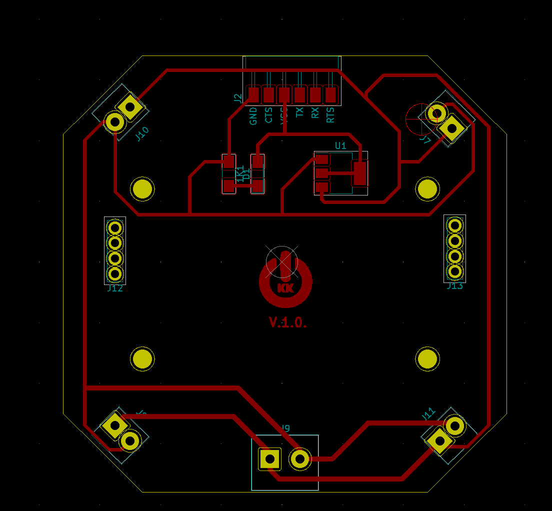
PCB DESIGN MADE WITH KICAD SOFTWARE
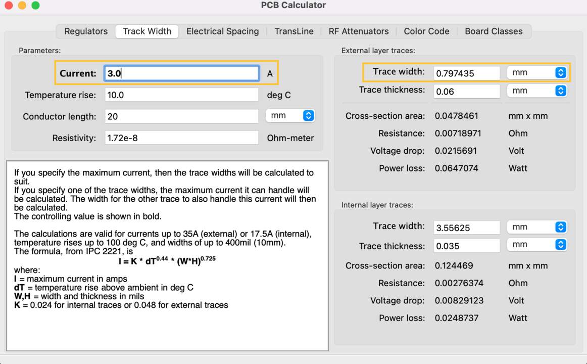
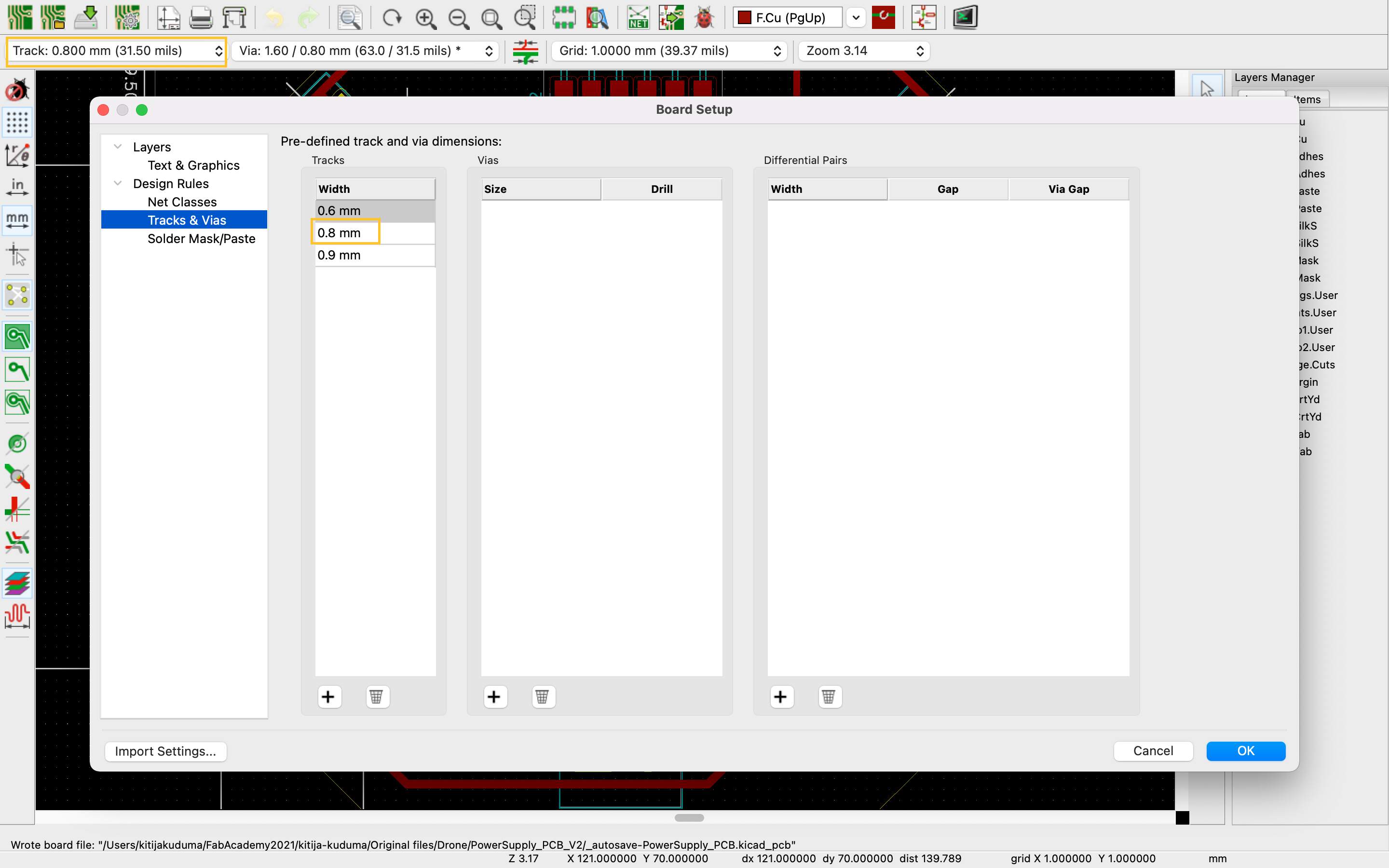
- As the experiments of the previous weeks have concluded that the maximum current during the operation of all four motors is 2.42 A, it is important to choose the appropriate thickness of the PCB feet - narrow, almost imperceptible paths are prohibited. It should not be invented by intuition, KiCad software has a good feature - PCB calculator. For safety reasons, I used 3A for calculations, but 2.54 would have been enough. The track width was calculated to be 0.79 mm. I clicked Edit pre-defined sizes and typed 0.8 mm. Tracks with this value will be the ones that will be moving from the incoming battery power component. In previous weeks, the track width for all boards was 0.4, but now, for example, I also increased the track width between 0.6 and Resistor to 0.6. So, the track sizes of this board are 0.8 and 0.6 mm.
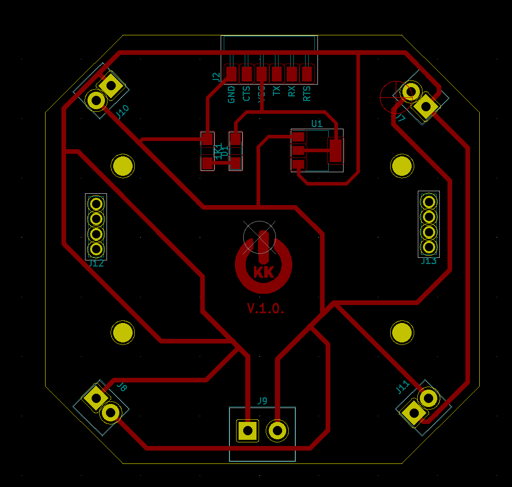
- During the initial work, the trace connections looked like the one in the picture, but instructor Kris suggested that it would be better not to make a transition from one route to another (in a circle), but to create like a spider type connection from the two main points of the battery power traces.
- In previous weeks on PCBs, I didn’t pay attention to how the board visually looked, but for the final work I wanted to include a little more design elements, so I tried to round the corners. The video tutorial I followed is available here. I spent a lot of time on the symmetry part - in the case of a drone, this is important because an accelerometer/gyroscope sensor is used.
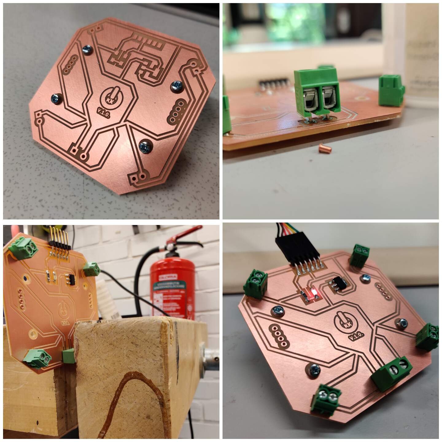
PROCESS & ISSUE & RESULT
V.1.0.
- For battery connection I used a screw terminal with a pitch size of 5 mm, for Electronic speed controllers (ESC) - screw terminals with a pitch size of 3.5 mm. Only during the soldering process I realized that for all screw terminals I used rivets with an outer size of 1.5 mm (inside - 1mm) and when I started to insert the battery screw terminal - it failed because it was bigger than others. The trouble was not so big - I clamped the PCB in the jaws and with a little force (if you repeat, then do not overdo it) screw terminal pressed.
- But what could be the solution? Do not insert the rivets for the battery connection or choose the same screw terminal size as ESC.
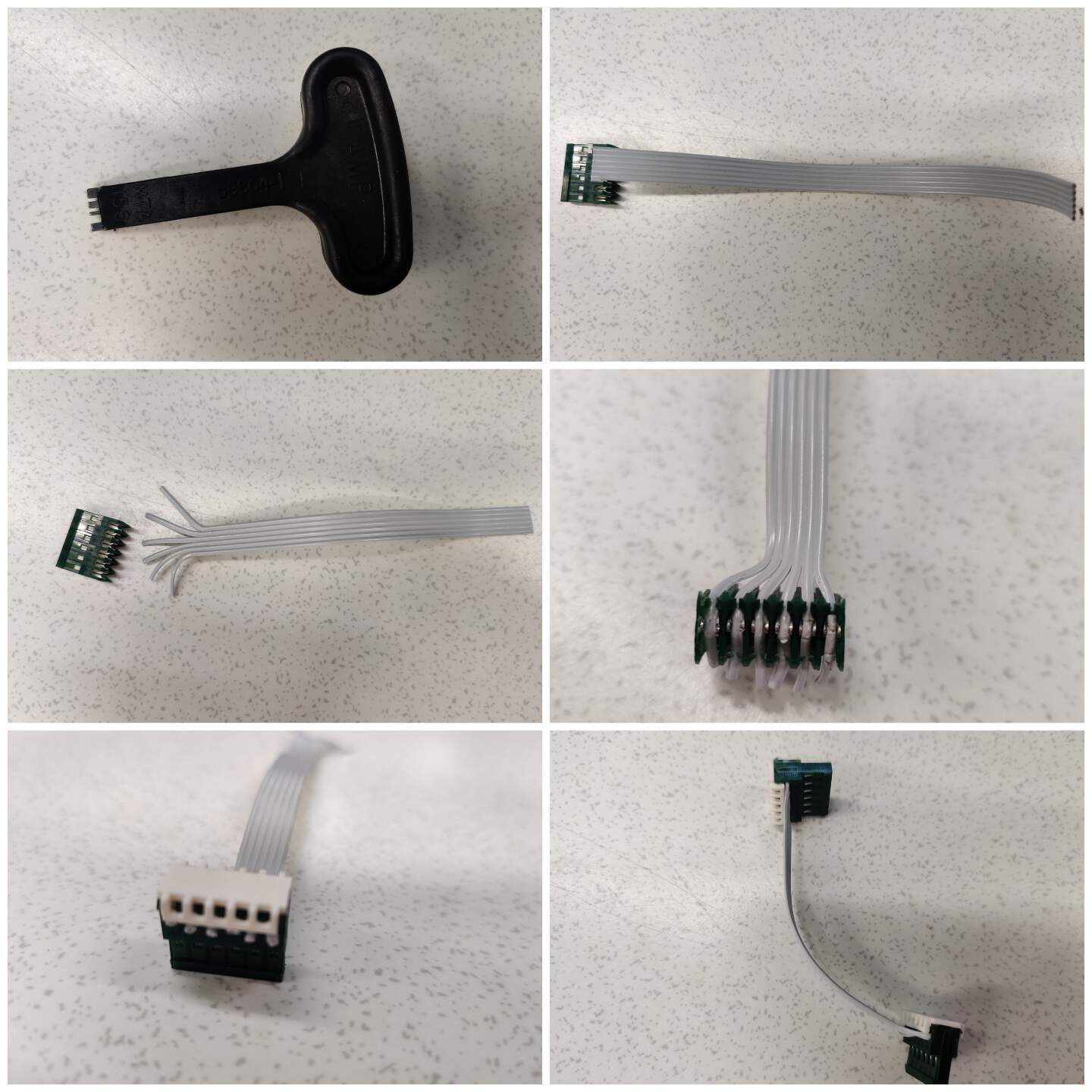
CONNECTION BETWEEN PCB
- In the system integration part it will be necessary to connect the power supply and the flight controller PCB to ensure power and drone operation. I learned how to make a wire connector - a tool which called a T-handle wire insertion tool, wires and connectors.