Week 9 - embedded programming
Architectures
In a von Neumann architecture the program and the memory are in the same place so they can interact. It is a more general architecture. In a Havard architecture they are separate. A Harvard architecture is more efficient.
RISC is a Reduced Instruction Set Computer and CISC is a Complex Instruction Set Computer. A RISC computer has a small set of simple and general instructions, rather than a large set of complex and specialized ones.
A microprocessor is the brain of a computer but it needs many chips around it to work. A microcontroller is the brain of a computer with the peripherals around it. The microcontroller is simpler but does more. A microprocessor won't work unless it has a bunch of other things to help it.
GPUs and TPUs are processors for parallel programming that has many processors cores in them. They are powerful for things like AI but they come with bigger packages, they are more expensive and take more power. FPGAs are Field Programmable Gate Arrays. FPGAs contain an array of programmable logic blocks, and a hierarchy of "reconfigurable interconnects" that allow the blocks to be "wired together", like many logic gates that can be inter-wired in different configurations. They don't have the capacity of a general purpose processor but in return they can make special purpose hardware that are much faster. Really big FGPAs are used to model new computer chips before they are made. Small FPGAs are good when you need a particular function to run it at very high performance like a video graphics driver for example.
They are also researches made to develop new kinds of architectures.
Later on in the FABACADEMY we will mainly use Harvard architecture with RISC instructions and microcontrollers.
Memory
Registers hold data that you are operating on. There is also RAM that holds data but in a traditional architecture, the processor can't work on the data in RAM. It has to move it into registers to work on it. But the SRAM is very quick. DRAM is cheaper and can be packed more densely but it's slower. As a consequence there is a hierarchy from DRAM to SRAM to registers. RAM forgets what it's doing when power is turned off. EPROM is memory that remembers what it's doing when you turn off the power. EEPROM is memory that can electrically program itself. FLASH is a type of EEPROM designed for high speed and high density. It is harder to program but denser. EEPROM is used to store things like configuration information and FLASH is mainly used to store programs that live in the processor. A typical microcontroller has much more FLASH than RAM. As a consequence if the microcontroller's program has strings of data such as messages that it sends to a user, it is worth to store strings in FLASH rather than in RAM because there is more FLASH available than RAM.
Fuses are special memories that configure the processor. They are like switches inside the microcontroller that will either be set or not set. They are used to switch on or off specific behavior in the microcontroller that are not normally changed during the execution of the program code. They control things like which oscillator to use, and what speed to run at (i.e. the internal 8MHz oscillator, or an external crystal), brownout detection, and the size of the boot flash. Here is a fantastic fuse calculator for ATmega AVRs. To understand them better several links are provided hereinafter: link_1, link_2, link_3, link_4 and link_5
Peripherals
Around the CPU (the brain of the chip) and in addition to the memory, there are ports that talk to the pins. The complexity here lays in the pin interface that can be output or input and can trigger in various ways.
They are Analog and Digital (A/D) converters that read a voltage into a sensor and translate it into a number. There are comparators that compare two different voltages. It seems less useful than A/D converter but comparators work faster than A/D converters.
A D/A converter turns numbers into voltages. They are used to make waveforms, e.g. for a speaker to make a sound. There are also timers that measure a lapse time, counters that measure events and PWM (Pulse Width Modulation) that vary the duration of pulses.
USART is a peripheral for serial communication. There must be USB drivers for USB communication and there can be many more peripherals.
Words
Little processors work on 8 bits at a time. There are also 16 bits processors. More powerful processors are 32 bits processors. Most of the desktop processors are 64 bits processors. More bits in a word means each instruction can do more work, which is good and it can address more memory, which is also good. But the chip gets bigger and crucially the packages get bigger. Typically more pins are needed when bigger sized words are used. One might think that the bigger the word size is, the better but 8 bits processors can still be attractive for their compactness and because they are working quite fast (at very high frequency) there is still a lot to do with them.
Families
To understand how works the logic inside processors there is an interesting project of a 4-bit calculator made entirely out of cardboard. Another project to understand how processors work has also been developed at Cambridge. It consists in a megaprocessor handcrafted by using one transistor at a time. On that page they also provide a link to a YouTube playlist explaining how works the logic with transistor. To summarize one transistor can be used as an inverter, two transistors in series as a NAND logic gate and two transistors in parallel as a NOR logic gate. They also explain the XOR logic gate and its implementation with transistors, the half adder made of the combination of an AND and a XOR gate, and how the combination of two half adders allows to do any summation. The last video of the series is about how works memory with the simplest memory element being the "Set Reset Latch" (arrangement of two NOR gates with cross coupling). It also details the behavior of a D-type Flip-Flop and a 2 bit counter.
8051 are an ancient family of microcontrollers. PICs are a pioneering embedded family. They are not designed around modern compilers.
AVRs are little processors designed around modern compilers. There are very powerful toolchains (the software that goes from software to hardware) using compilers designed for modern computers that work on these little embedded processors. They are made by Microchip. Microchip also made PICs then it merged with Atmel and they made AVR.
ARM is a UK company that came up with design of chips other people make.
Xtensa is a family that dates back to another lineage from what's called MIPS. Those were used by a company expressive to come up with the ESP family which is notable for having good radios built into it, for Bluetooth and Wi-Fi.
RISC-V is a very interesting project on a completely open architecture for processors. They are just coming on the market and the toolchains are just emerging.
Finally there is a bunch of specialized families of microcontrollers. PSoC have real cheap dev-boards and these are processors with a whole bunch of peripherals that let you make a whole system by how you configure it. xCORE, Propeller and Lattice are all examples of multicores. Rather than having one processor in the package, each of these have many different processors in one package. NVIDIA has these embedded GPUs that can hundreds or thousands of processors in one package and they are used for things that are really compute-bound such as AIs, vision systems.
Vendors and Packages
Octopart is a fast search engine for electronic parts. It is very handy to check the stock across hundreds of distributors and thousands of manufacturers.
On the distributors sites, microcontrollers are sold within different packages. There are many types of IC (Integrated Circuit) packages, each having unique dimensions, mounting types and/or pin counts. Most common IC package types include DIP, surface-mount device (SMD), small-outline package (SOP), quad-flat package (QFP) and ball-grid array (BGA). They are illustrated in the following picture.
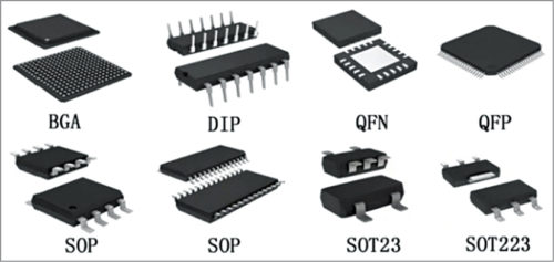
Different types of IC (Integrated Circuit) packages
In-system development
In-system development is about how to load programs into the chip. There are different options depending on the family type.
ISP
The original AVRs use an ISP (In-System Programming) protocol. AVRDUDE is a software program that talks to the hardware and its job is to convert the program you wrote and load it into the processor. Then you needed to physically get it in by using for instance a programming header and a programmer. There are commercially available programmers to do that job but an Arduino can also be used as an ISP to load a program into AVRs.
UPDI
Newer versions of AVRs, instead of using ISP, use a different protocol called UPDI. What is interesting about UPDI is that it requires only 2 pins (one data pin that goes in two directions and one ground pin) when the ISP requires a 10 pins connector. UPDI programming is simpler because there is only one logic line for it but it is also more versatile, it lets you do various kinds of in-system development. pyupdi is a software program that converts your program into this program to load it in these newer AVRs. Three hardware solutions are proposed: a serial to UPDI converter (but it requires an interface between the computer and the serial ports), a FTDI/UPDI converter (it uses a FTDI chip connected to a USB port on one side and a UPDI port on the other side) or an Arduino as a UPDI programmer.
JTAG
A standard solution for ARM parts is OpenOCD or EDBG. EDBG takes your program and loads it into the microcontroller. This can be done by using a commercially available programmer (Atmel-ICE), or a Raspberry Pi, or a DIY programmer.
Bootloaders
Bootloaders are programs that load programs. To load the bootloader, one of the programs above is needed. Once the bootloader is loaded the programmer is not needed anymore, the interface of the board can be directly used to load other programs.
Assembly language
At the bottom of the assembly language there is hexadecimal code. In the chip you load an .hex file. Above it is the instruction set. you can write those codes by hands but nobody does that anymore because processors are now designed around modern compilers.
C
C is the most common programming language used for programming chips. It is above assembly language and below a high level language. It is very efficient. Here is a nice tutorial to learn C. GCC is an open compiler. The toolchain is the thing that turns the C program into the .hex file.
For the AVR as well as ARM we use libraries to set the programming environment. Microchip also have a studio to write, build and debug applications written in C/C++ or assembly code. But the GCC toolchains are so popular Microchip also supports that directly.
IDE
IDEs are Integrated Development Environments. Atmel Studio and Arduino are two of them. They let you write the code, load the code, run the code and debug the code.
Arduino
There might be some confusion around the use of the word Arduino. This is due to the fact that Arduino can refer to six different things. Arduino can either be referred as a board, a toolchain, a set of libraries, an IDE (an environment you can use to do embedded programming), a standard set of bootloaders or a form factor for headers.
Programming with Arduino mainly means programming in C but with libraries dedicated to electronics programming. The original Arduino was designed around the Mega328 but what is really nice with Arduino is that Arduino Cores let you use the Arduino IDE with other processors. One might use another IDE than Arduino to write its code because there are more powerful IDEs than Arduino's, but still Arduino can be very useful because underneath its IDE there is the toolchain that allows to load the program in many types of microcontrollers. The core is the toolchain, it also includes the thing that loads the program, it can include the bootloader, but its main job is taking the software, converting it to code and loading it to hardware.
Clocks
Some microcontrollers let you use external clock to be more accurate or let you overclock them which means that you can run them faster and they should work without guarantee but with higher performance.
Host communication
RS232 is a full standard, including voltage levels. Here is a list of terminals that can be installed on a computer:
You can also talk through USB. Older processors use software USB and newer processors use hardware USB. And if you want to convert between serial RS232 and USB there are chips from FTDI that make that conversion.
FAB ACADEMY 2020 source
20200318 Embedded Programming from Academany on Vimeo.
My Assignment
This week assignment consists in reading a microcontroller datasheet and programming a board to do something, with as many different programming languages and programming environments as possible.
To know about the group assignment, please follow this link.
Reading a datasheet
Lorem ipsum dolor sit amet consectetur.
- 32-bit ARM processor
- 14 pins
- maximum frequency: 48MHz
- 2.46 Coremark/MHz
- simple and intuitive migration with identical peripheral modules, hex compatible code, identical linear address map and pin compatible migrations paths between all devices in the product series.
The Atmel SAM D11 devices provide the following features:
- In-system programmable Flash,
- six channel direct memory access (DMA) controller,
- 6 channel Event System,
- programmable interrupt controller,
- up to 22 programmable I/O pins,
- 32-bit real-time clock and calendar,
- two 16-bit Timer/Counters (TC) and one 24-bit Timer/Counter for Control (TCC), where each TC can be configured to perform frequency and waveform generation, accurate program execution timing or input capture with time and frequency measurement of digital signals. The TCs can operate in 8- or 16-bit mode, selected TCs can be cascaded to form a 32-bit TC, and one timer/counter has extended functions optimized for motor, lighting and other control applications.
The series provide:
- one full-speed crystal-less USB 2.0 device interface;
- up to three Serial Communication Modules (SERCOM) that each can be configured to act as an USART, UART, SPI, I2C up to 3.4MHz, SMBus, PMBus and LIN slave;
- up to 10-channel 350ksps 12-bit ADC with programmable gain and optional oversampling and decimation supporting up to 16-bit resolution, one 10-bit 350ksps DAC, two analog comparators with window mode, Peripheral Touch Controller supporting up to 72 buttons, sliders, wheels and proximity sensing;
- programmable Watchdog Timer, brown-out detector and power-on reset; and
- two-pin Serial Wire Debug (SWD) program and debug interface
All devices have accurate and low-power external and internal oscillators. All oscillators can be used as a source for the system clock.
The SAM D11 devices have two software-selectable sleep modes, idle and standby. The device supports SleepWalking. The Event System supports synchronous and asynchronous events, allowing peripherals to receive, react to and send events even in standby mode.
The Flash program memory can be reprogrammed in-system through the SWD interface. The same interface can be used for non-intrusive on-chip debug and trace of application code. A boot loader running in the device can use any communication interface to download and upgrade the application program in the Flash memory.
The Atmel SAM D11 devices are supported with a full suite of program and system development tools, including C compilers, macro assemblers, program debugger/simulators, programmers and evaluation kits.
| Configuration Summary | SAM D11C - 14-pin SOIC |
|---|---|
| Pins | 14 |
| General Purpose I/O-pins (GPIOs) | 12 |
| Flash | 16KB |
| SRAM | 4KB |
| Timer Counter (TC) | 2 |
| Waveform output channels for TC | 2 |
| Timer Counter for Control (TCC) | 1 |
| Waveform output channels per TCC | 8 |
| DMA channels | 6 |
| USB interface | 1 |
| Serial Communication Interface (SERCOM) | 2 |
| Analog-to-Digital Converter (ADC) channels | 5 |
| Analog Comparators (AC) | 2 |
| Digital-to-Analog Converter (DAC) channels | 1 |
| Real-Time Counter (RTC) | Yes |
| RTC alarms | 1 |
| RTC compare values | 1 32-bit value or 2 16-bit values |
| External Interrupt lines | 8 |
| Peripheral Touch Controller (PTC) channels (X- x Y-lines) for mutual capacitance | 12 (4x3) |
| Peripheral Touch Controller (PTC) channels for self capacitance (Ylines only) | 7 |
| Maximum CPU frequency | 48MHz |
| Packages | SOIC |
| Oscillators | 32.768kHz crystal oscillator (XOSC32K) 0.4-32MHz crystal oscillator (XOSC) 32.768kHzinternal oscillator (OSC32K) 32kHz ultra-low-power internal oscillator (OSCULP32K) 8MHz high-accuracy internal oscillator (OSC8M) 48MHz Digital Frequency Locked Loop (DFLL48M) 96MHz Fractional Digital Phased Locked Loop (FDPLL96M) |
| Event System channels | 6 |
| SW Debug Interface | Yes |
| Watchdog Timer (WDT) | Yes |
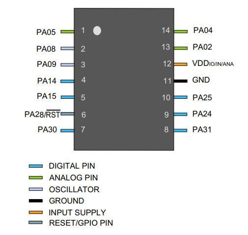
Schematics of the SAM D11C 14-pin SOIC
Each pin is by default controlled by the PORT as a general purpose I/O and alternatively it can be assigned to one of the peripheral functions A, B, C, D, E, F, G or H.
Programming with the Arduino IDE
This part of the assignment was already done during WEEK 7.
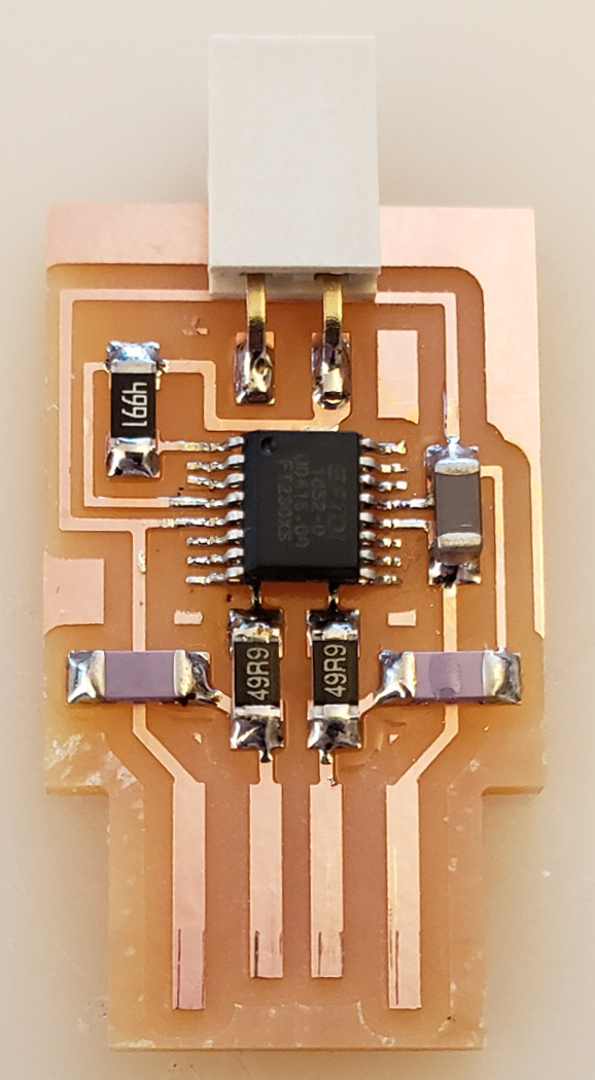
Testing of my PCB board
Programming with Atmel Studio
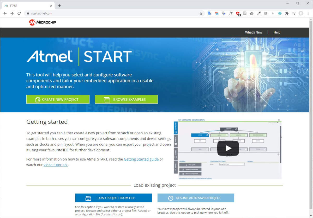
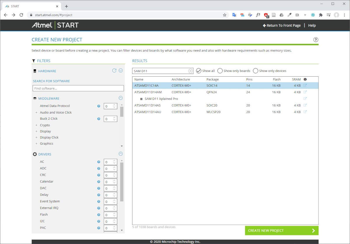
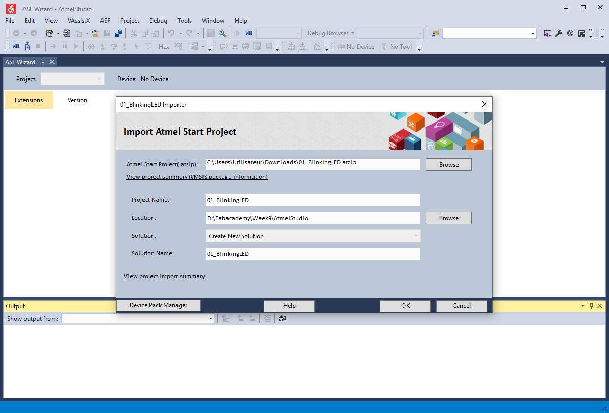
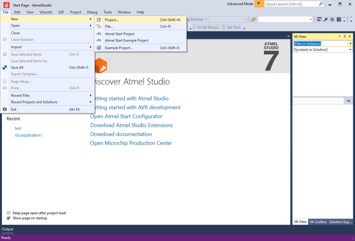
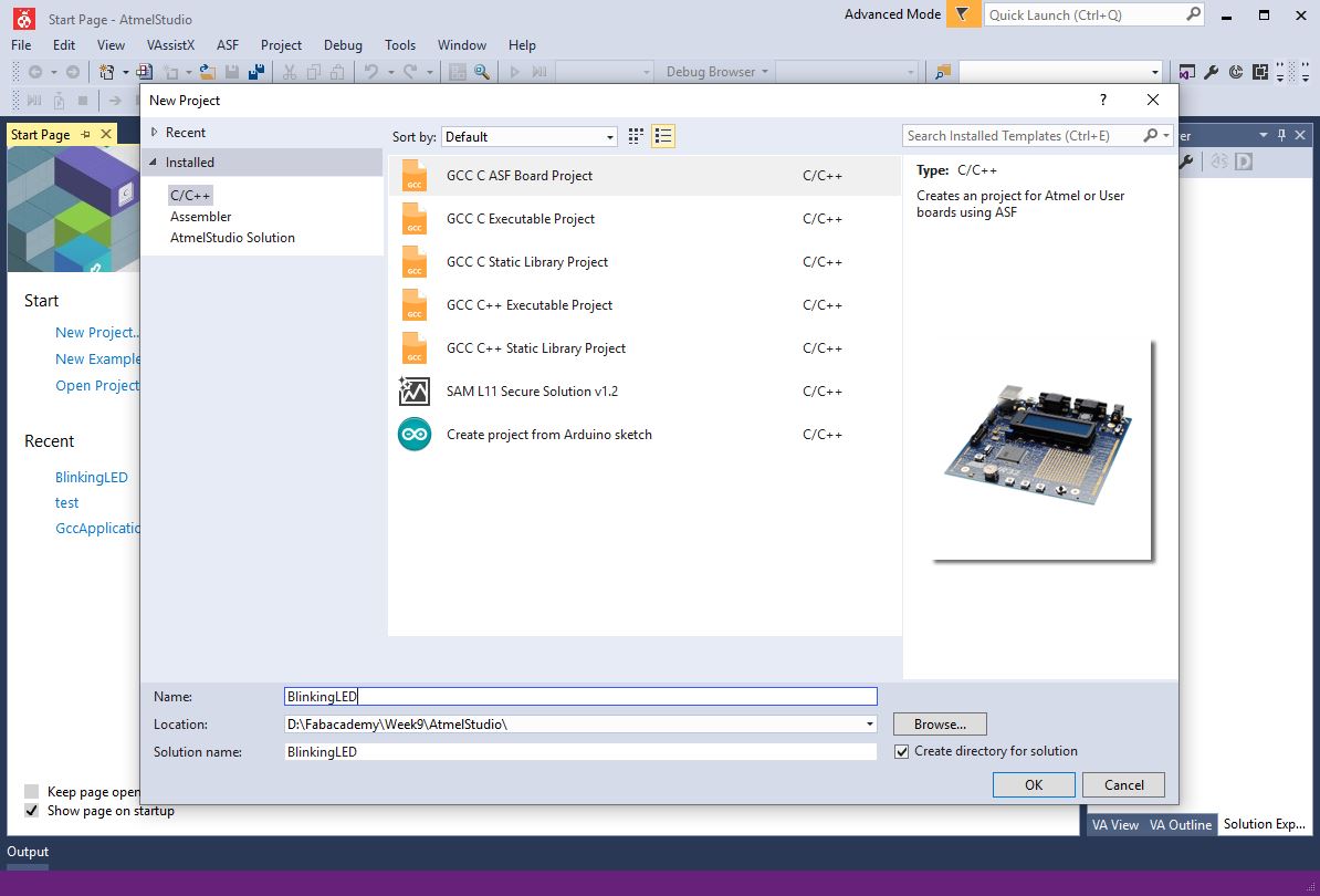
I also tested another programming environment to program my board: Atmel Studio 7. After the software installation, to get starting with this programming environment, I followed this tutorial. My objective was to make a blinking LED. As a consequence I browsed the following webpage: https://start.atmel.com/. Then I clicked on CREATE NEW PROJECT.
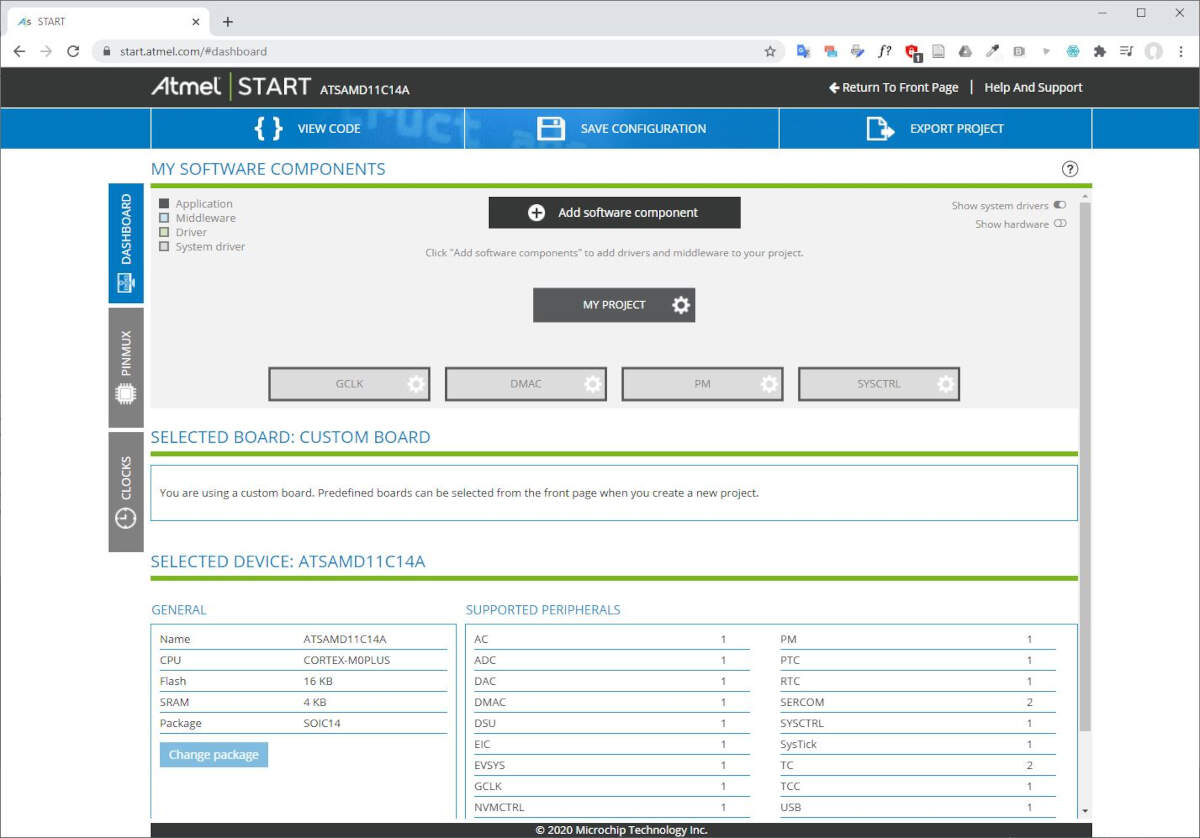
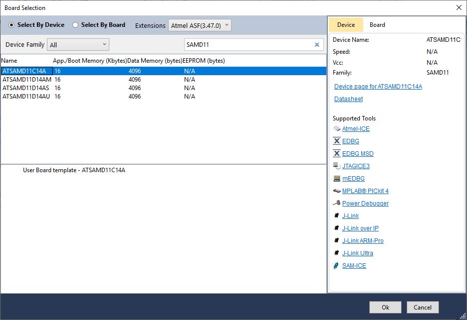
I selected my microchip ATSAMD11C14A and I clicked on CREATE NEW PROJECT.
I renamed my project by clicking on MY PROJECT.
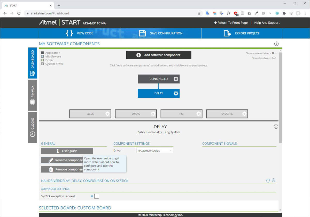
Then I clicked on Add software component to enable the delay functionality that is essential to make a blinking LED.
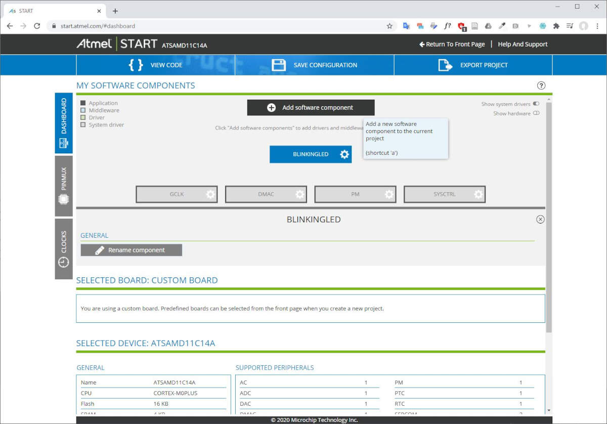
I selected the Delay functionality.
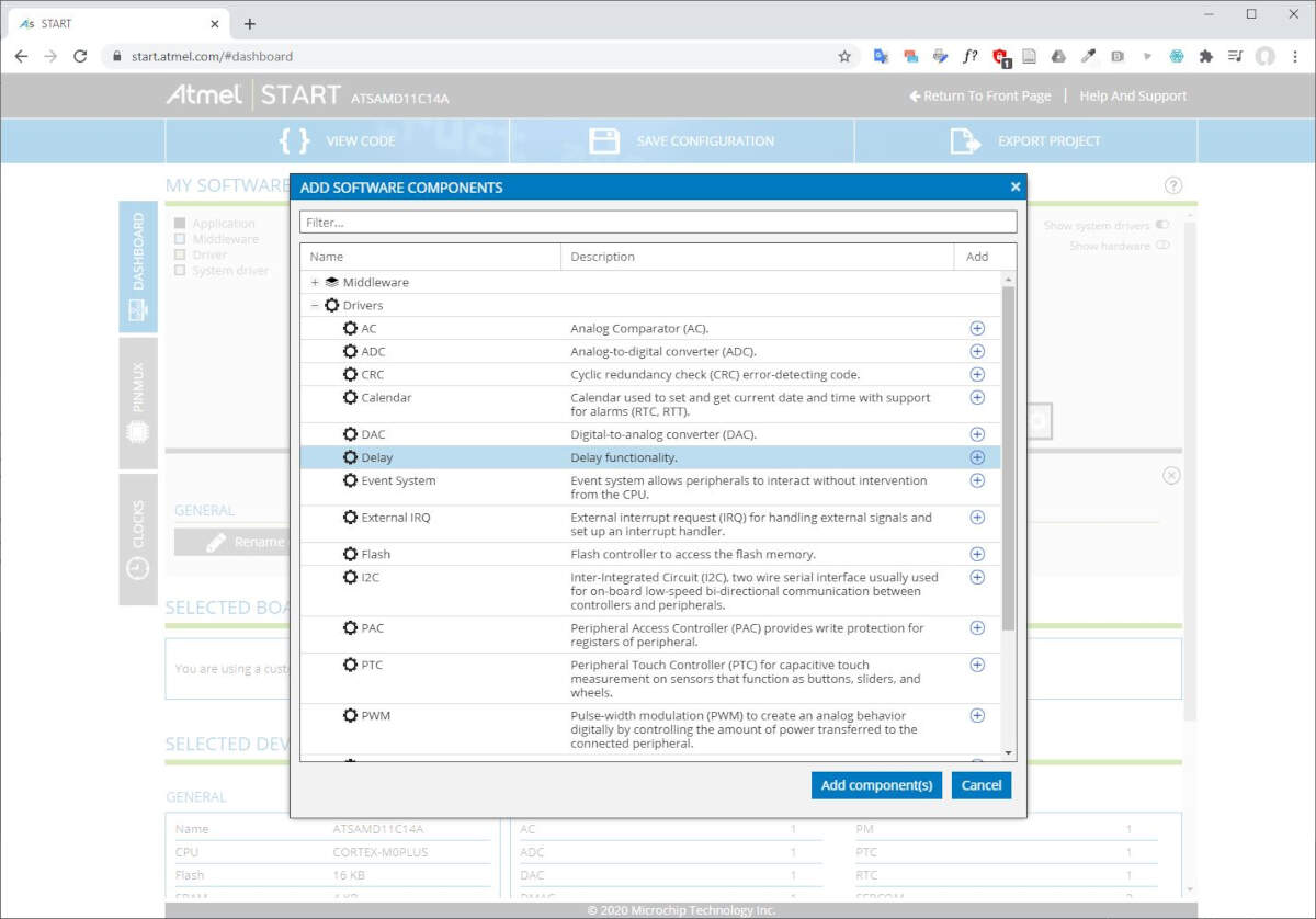
Note that once added the user guide of the functionality is available on the main webpage.
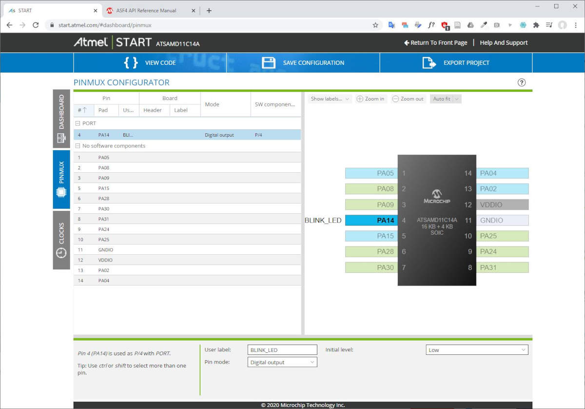
Then, under the PINMUX tab, I configured PA14 as an output. That is the pin that is physically connected to the led. I gave it a name, BLINK_LED, and I set its initial value to low.
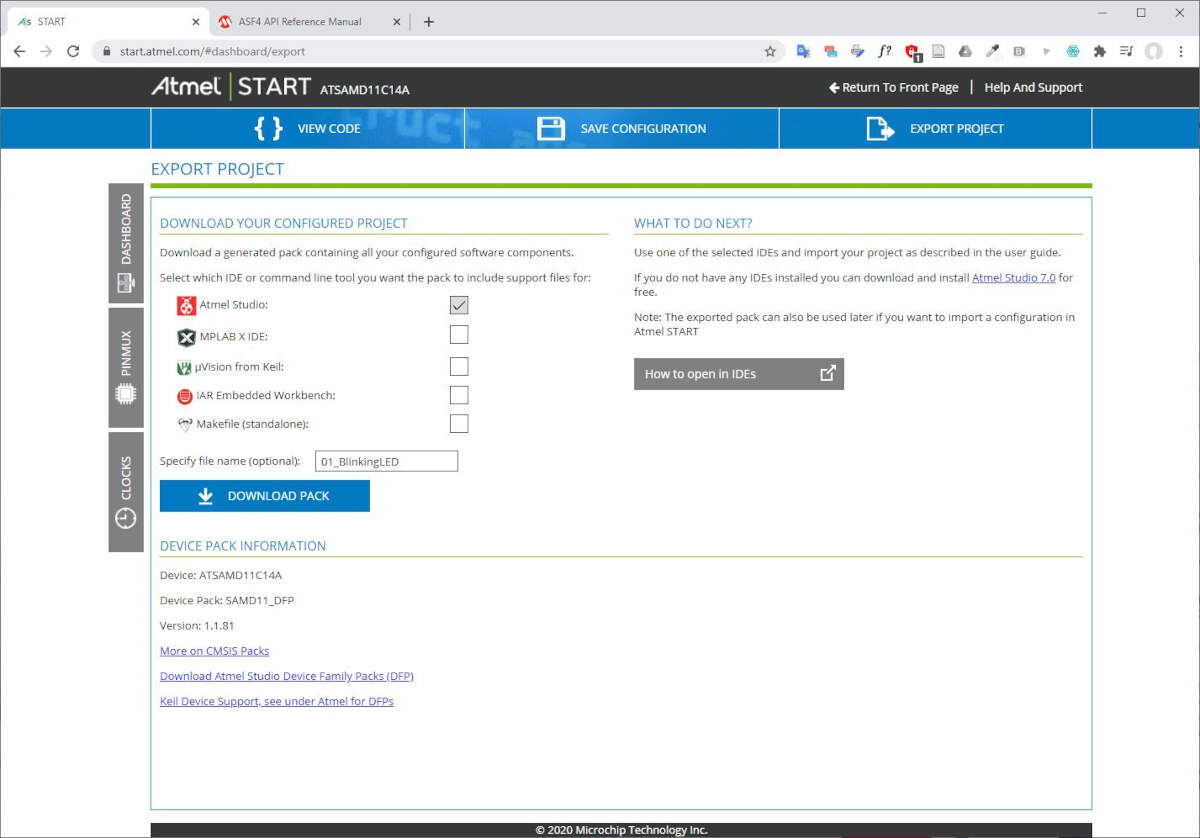
Finally I clicked on EXPORT PROJECT in the navigation bar. I ticked the IDE Atmel Studio, I specified the file name and I clicked DOWNLOAD PACK.
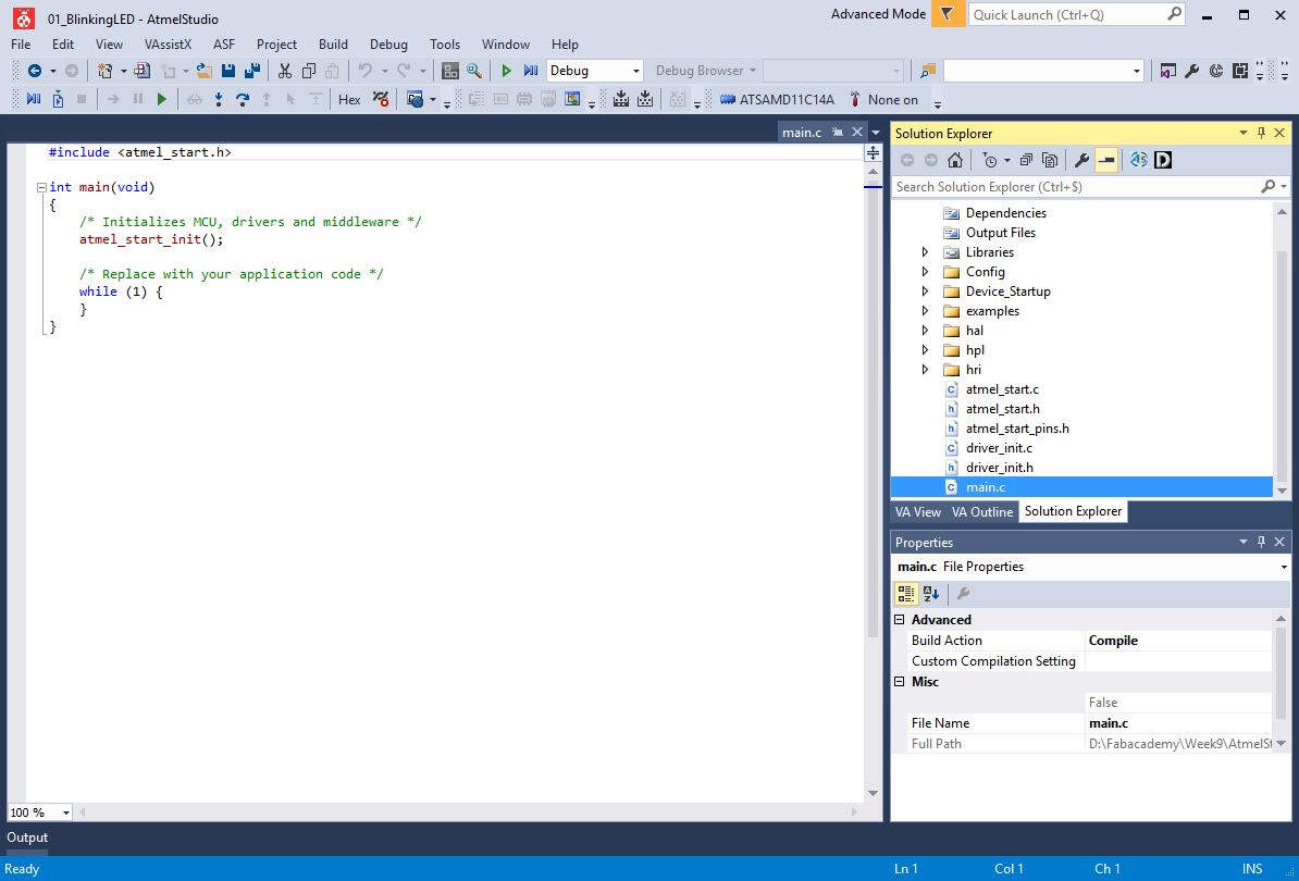
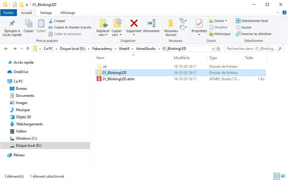
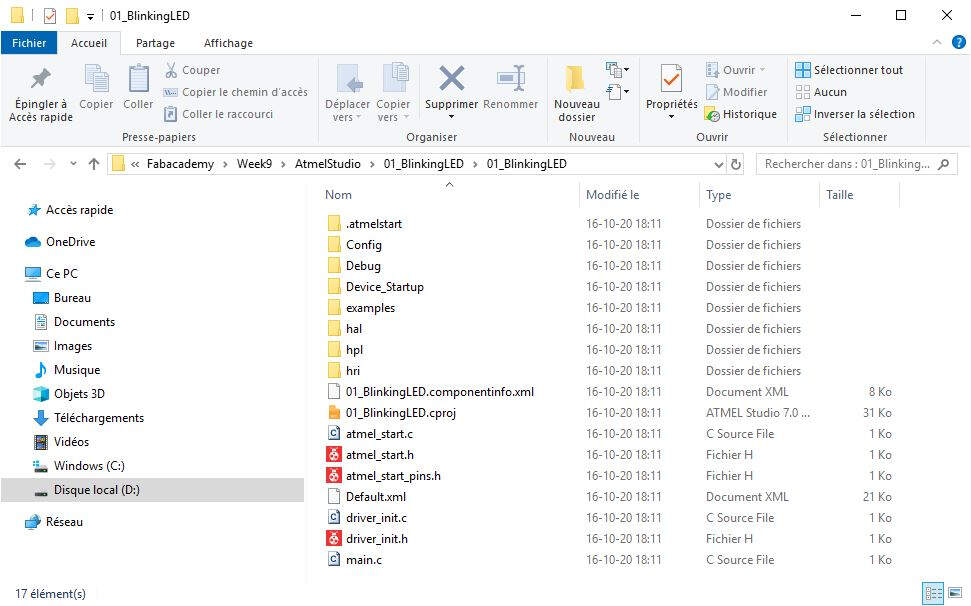
In Atmel Studio I imported the files previously created with ATMEL Start.
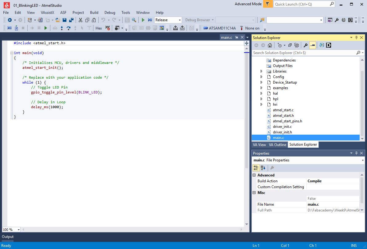
The main.c file includes the atmel_start.h file. In the Solution Explorer, I explored the several files that are called after the atmel_start.h file.
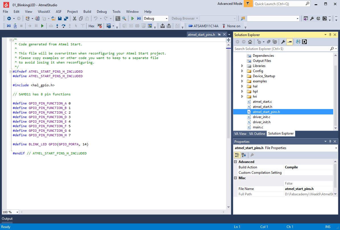
Among these files there is the atmel_start_pins.h file where the name of pin 14 is defined: #define BLINK_LED GPIO(GPIO_PORTA, 14).
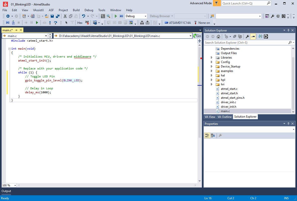
To make the blinking LED I modified the main.c code by using the function gpio_toggle_pin_level(BLINK_LED); and delay_ms(1000);.
At that stage the files generated for my ATMEL STUDIO project are the following.
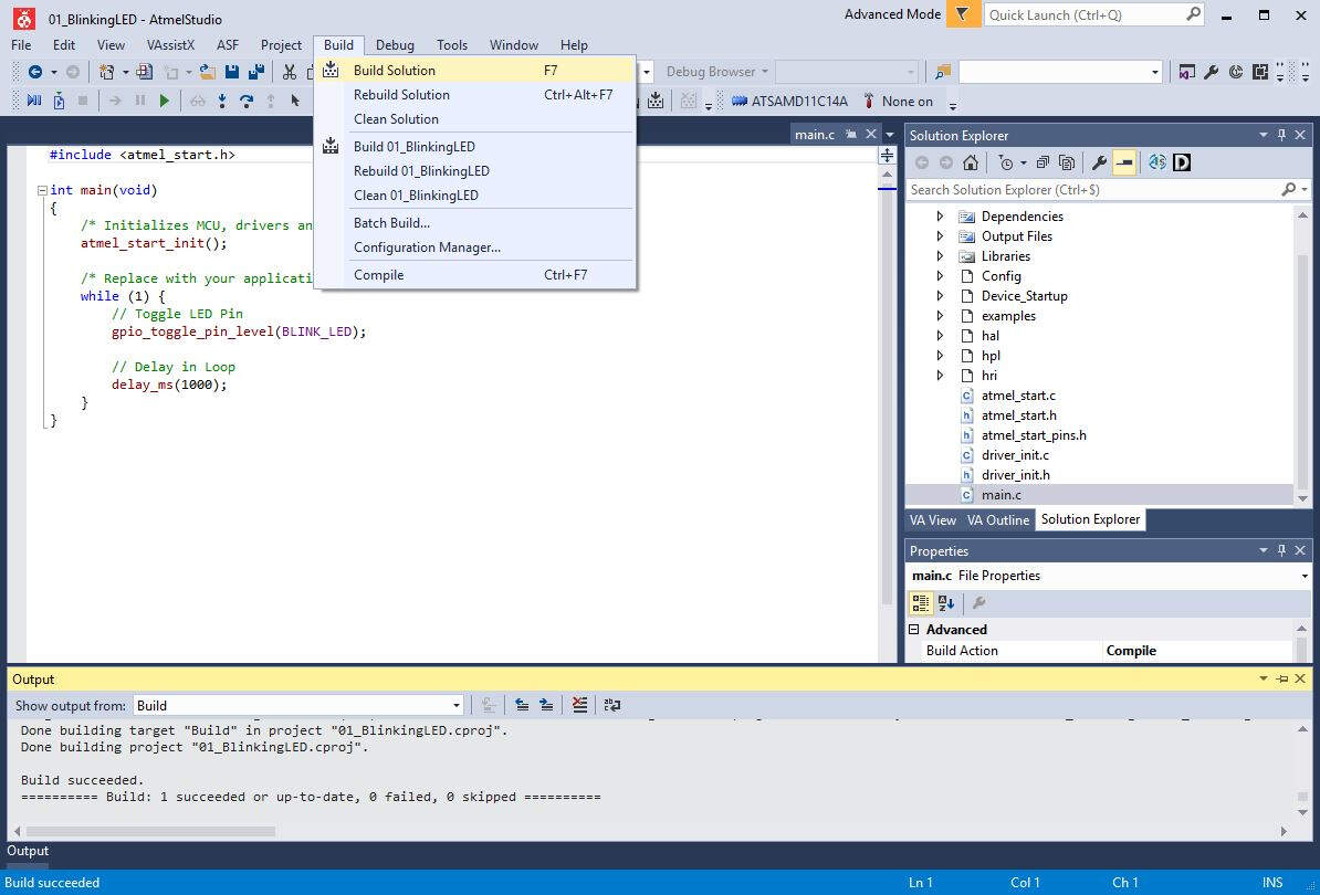
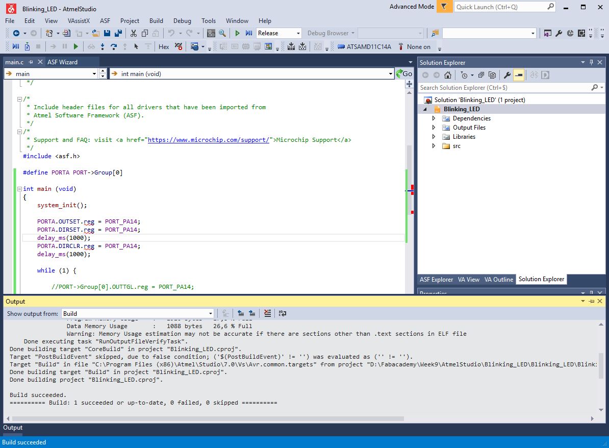
In Release mode I built the solution.
This was done by clicking the F7 or on Build -> Build Solution.
Now the project folder contains a new folder, the folder Release, where a binary file can be found.
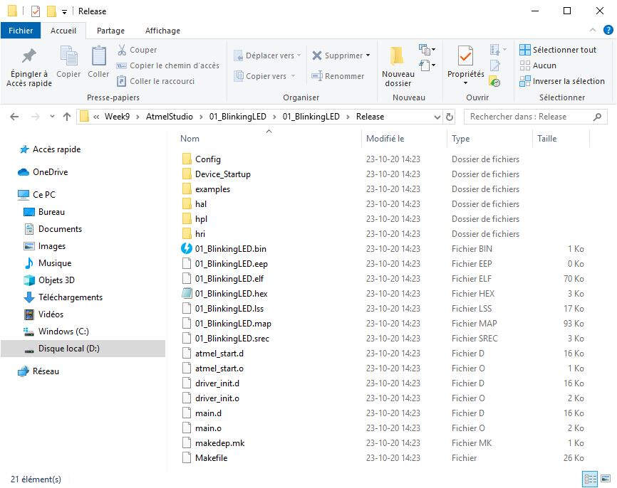
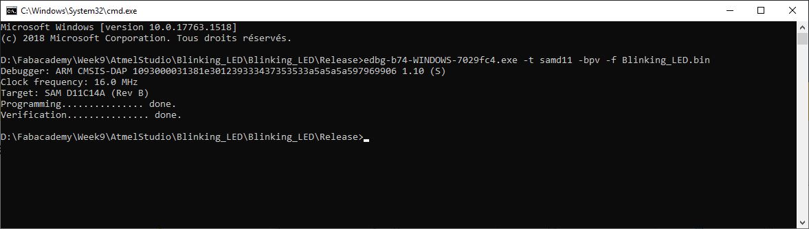
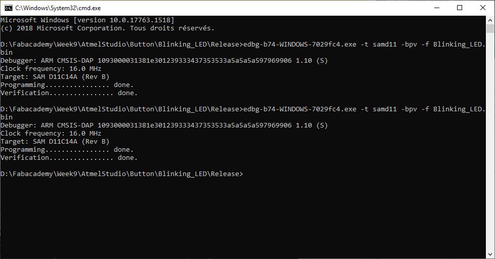
I pasted this binary file and copied it in another folder with edbg.
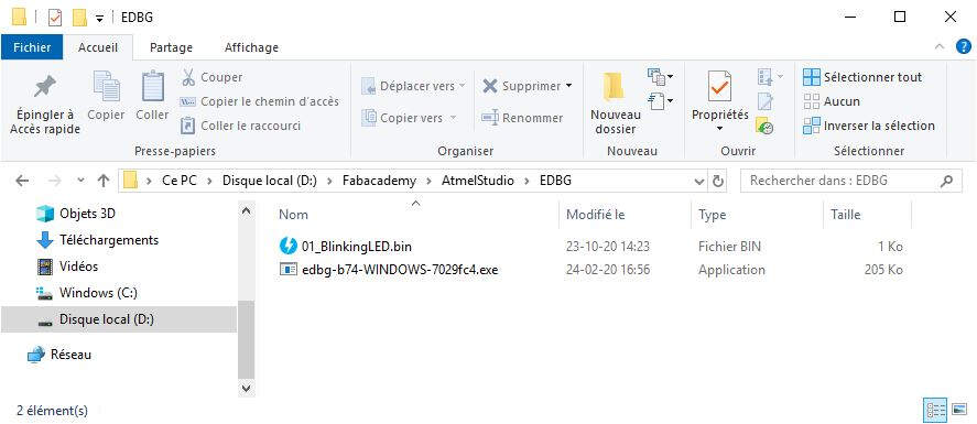
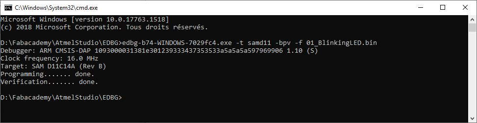
At this location I opened a command prompt to load the program with my particle programmer and edbg. I ran the command edbg-b74-WINDOWS-7029fc4.exe -t samd11 -bpv -f 01_BlinkingLED.bin and the program loaded successfully.
Here is a video of the result.
Programming with Atmel Studio
Afterwards I created a variant of this program. In this program the LED turns on for 4 seconds then turns off for 1 second.
#include <atmel_start.h>

int main(void)
{
	/* Initializes MCU, drivers and middleware */
	atmel_start_init();

	/* Replace with your application code */
	while (1) {
		gpio_set_pin_level(BLINK_LED,1);

		// Delay in Loop
		delay_ms(4000);

		gpio_set_pin_level(BLINK_LED,0);

		// Delay in Loop
		delay_ms(1000);
	}
}
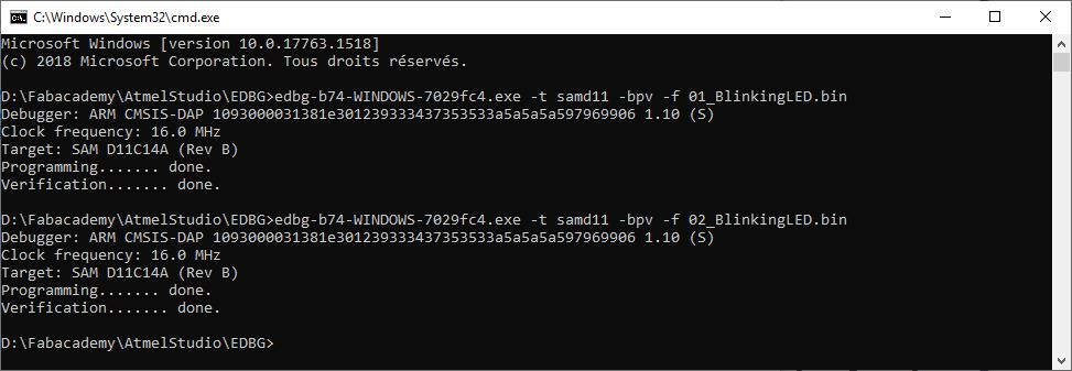
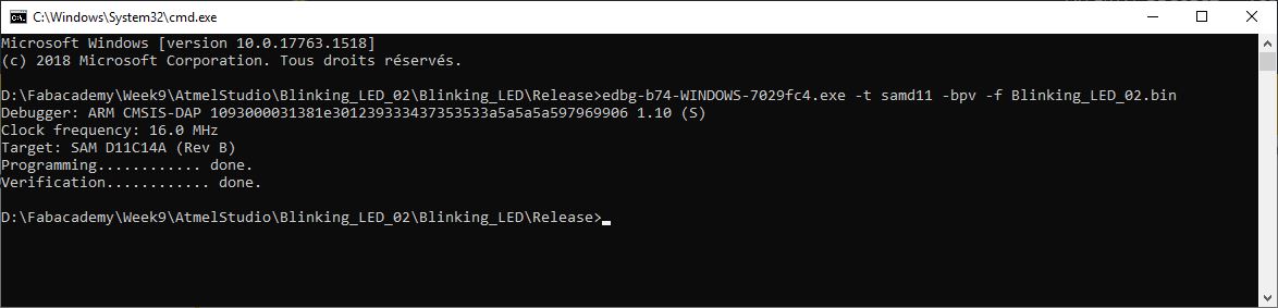
Once built the binary release I loaded it with edbg.
I also found the ASF programmers manual that gives information about the several commands (in particular on GPIOs) that can be used to program the ATSAMD11. This might be also useful to start a project from scratch without using ATMEL START. More information can also be found on this tutorial. This video also explains a different way of starting with ATMEL SMART SAMD and configuring the GPIOs.
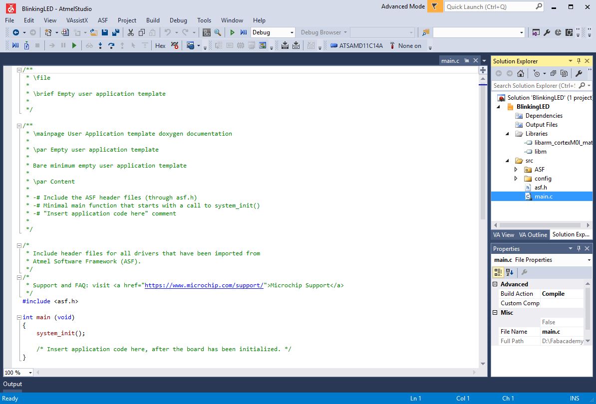
Based on these sources, I also created a ASF project.
In Atmel Studio, I clicked on New -> Project....
I click on GCC ASF Board Project and I gave a name to my project.
I selected my board ATSAMD11C14A.
After that Atmel Studio created a bunch of files among them main.c. This is the file that will be modified.
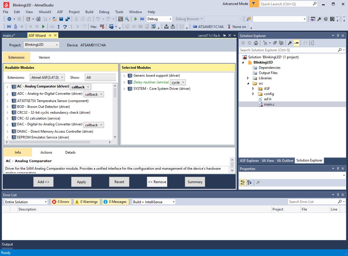
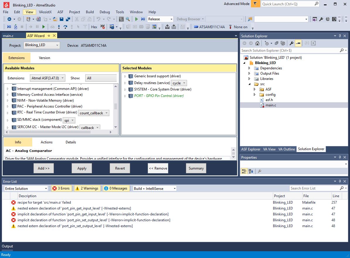
The libraries need to be referenced manually thanks to the ASF wizard.
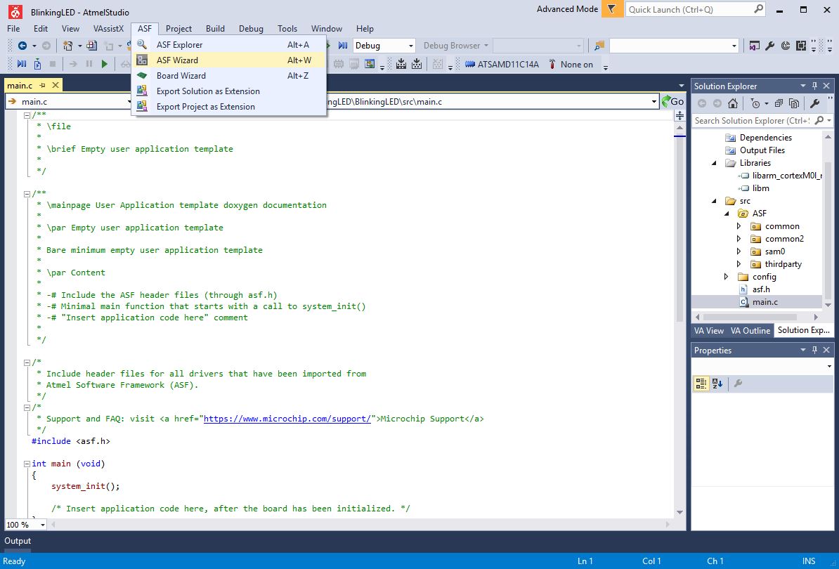
This is the ASF wizard and by default there are only two selected modules.
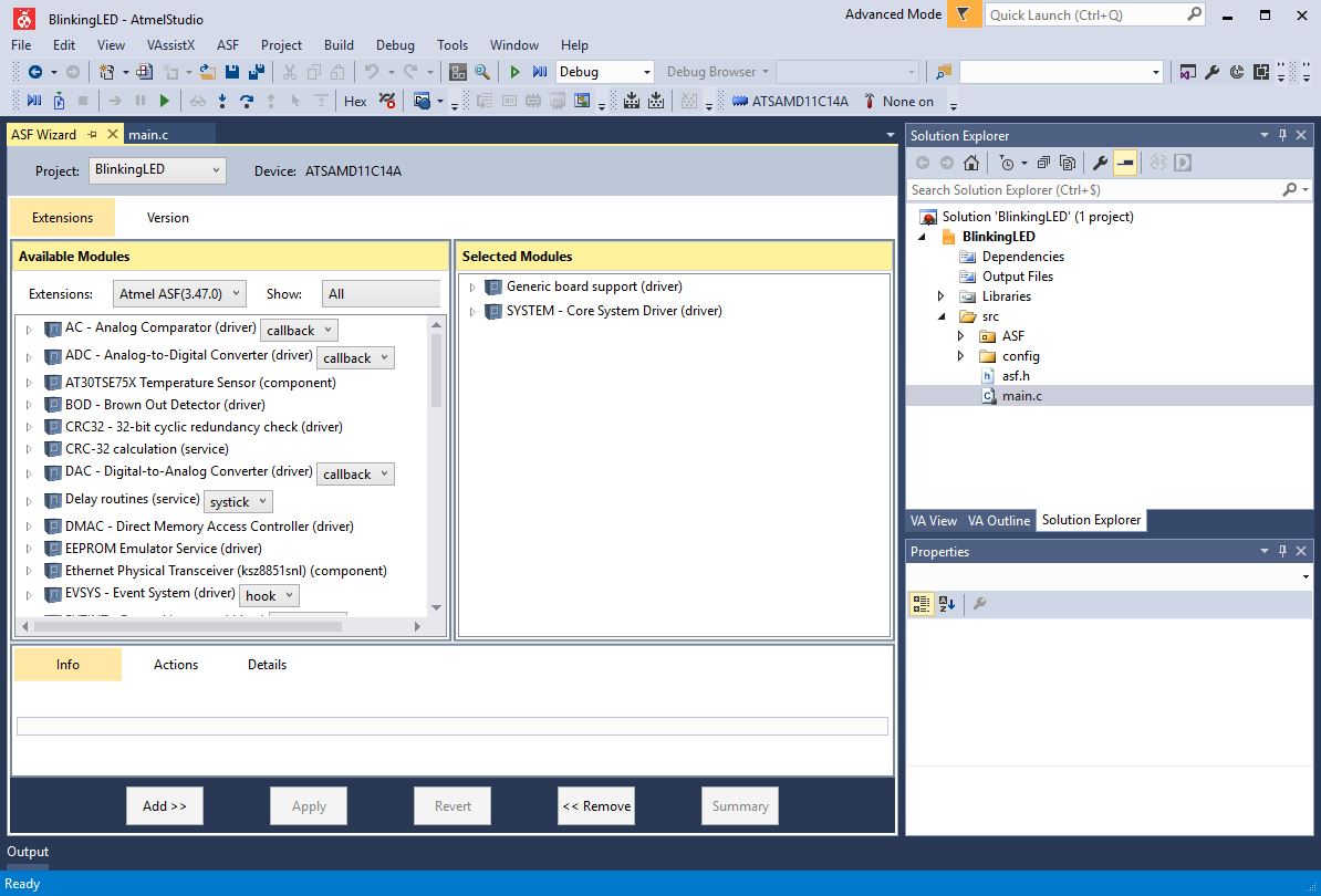
I added the Delay routines service to be able to use the function delay_ms().

After clicking on Apply a summary of operations appeared and I clicked OK.
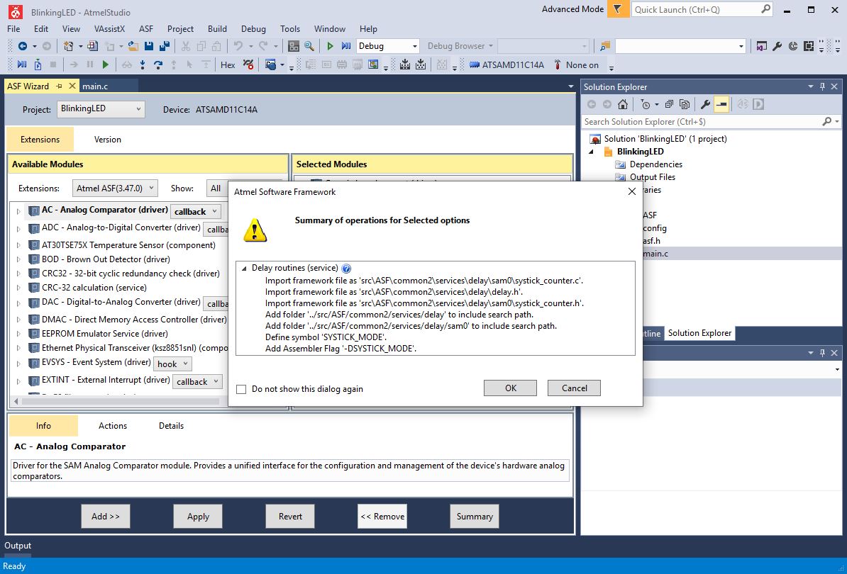
It is very important to set the parameter of the Delay routines service on cycle. Otherwise the debugger will give no error but the code will not work on the microchip. Don't forget to click on Apply.
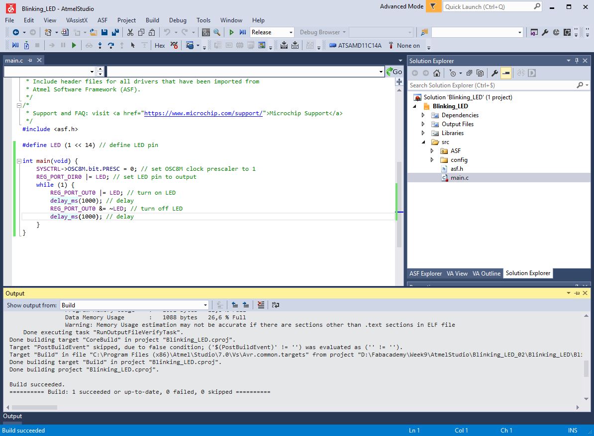
I modified the main.c code and then I built the solution.
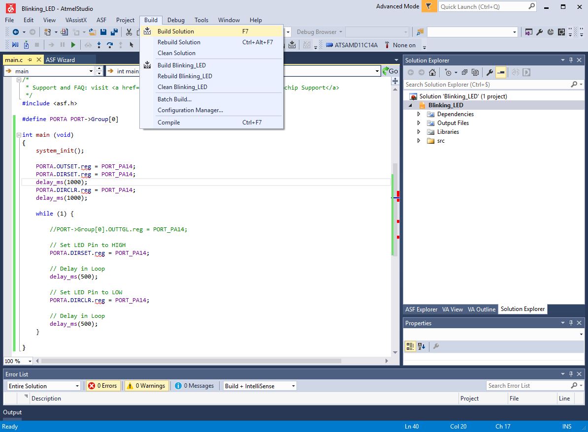
It gave not error.
I finally loaded on my ATSAMD11C14A with edbg and it worked.
Then I created another ASF project with another way of coding.
It also gave satisfying results.
Then I created a last project in which I would use the button connected to pin PA15.
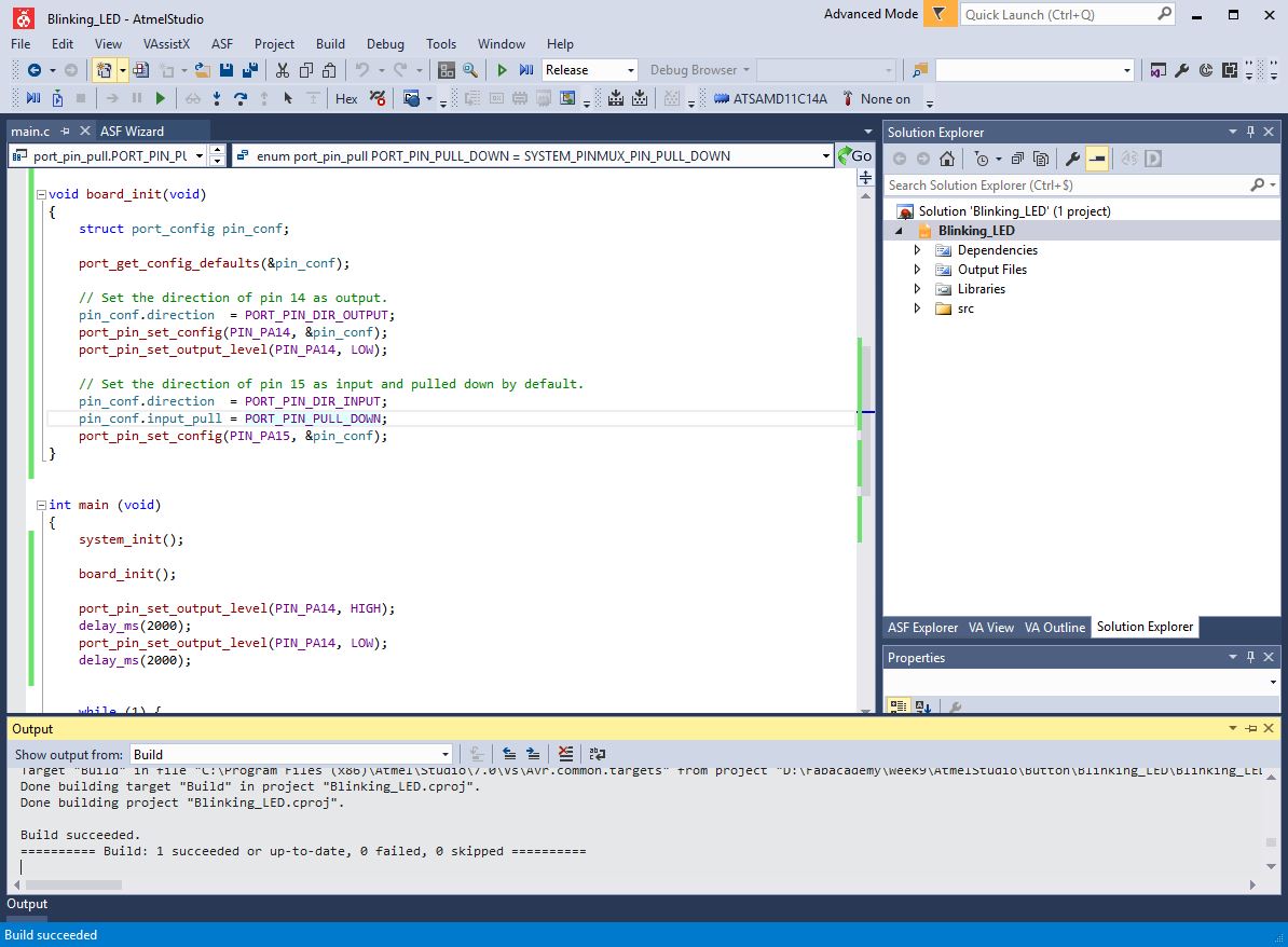
To write this code I used the PORT - GPIO Pin Control library.
Building the solution in release mode gave not error.
And the code gave satisfying results on the board.
Files
ASF Projects