Week 7 - electronics design
This week was dedicated to electronics design. The objective of this week was to get familiar with electronics components such as buttons, wires, switches, resistors, capacitors, inductors, diodes, transistors, batteries and microcontrollers. It also aimed at learning more about the software meant to help electronics design.
FAB ACADEMY 2020 source
20200304 Electronics Design from Academany on Vimeo.
My Assignment
This week the group assignment consisted in using the test equipment in our lab to observe the operation of a microcontroller circuit board.
This week the individual assignment consisted in redrawing an echo hello-world board and adding at least a button and LED (with current-limiting resistor). This exercise was meant to get familiar with PCB design software. I chose to redraw the hello.D11C.echo since I already used an ATSAMD11C during the WEEK 5 about electronics production.
On that echo hello-world board I decided to add one reset button, one button and one blue led each connected to a pin of the ATSAMD11C and one green led to check that the 3.3V is correctly delivered after the voltage regulator.
Description of the electronic components
ATSAMD11C
The ATSAMD11C datasheet was available on DigiKey. A link to UltraLibrarian was also provided to download the EDA and CAD models of the microchip. It is interesting to note that more than one result was given when looking for the ATSAMD11C14A on DigiKey. The only thing that differentiates these results is the packaging but the product was the same for both.
Linear Voltage Regulator - TLV70233DBVT
By doing a web research with the product name of the linear voltage regulator as entry I easily found the datasheet of the TLV70233DBVT linear voltage regulator on DigiKey. On its website this vendor also provides a link to download the EDA and CAD Models from UltraLibrarian. In the datasheet there is a typical application circuit schematic where there are two small, 1-μF ceramic capacitors: one at the input pin and one at the output pin. The small, 1-μF ceramic capacitor is only recommended on the input while its is needed from this pin to ground to assure stability. In this regulator there also is a enable pin which turns the regulator on when the EN pin is driven over 0.9 V.
USB
The main characteristic of the USB architecture is that it also provides power supply to peripherals. It consists of 4 cables: the ground GND, the power supply 5V, and two data wires D- and D+. The D- and D+ wires consist in a twisted pair and use the differential signaling principle to guarantee a relative immunity against external noises (e.g. electromagnetic fields) on the peripheral or its cable.
LEDs
For the blue and green LEDs I checked the datasheets to be able to compute the value of the resistor required to limit the current through the LED. I also looked at the size of the LED and I found 1206 [3216 Metric] for both. This information was very useful to choose the right foot print in the components libraries.
Libraries
Component libraries are important because they allow to charge the right electronic components with the right foot print and schematic. They help a lot to ease the electronics design and routing. On EAGLE I used several components libraries. The first one I downloaded is the FABACADEMY library. To add the library to EAGLE I followed this tutorial. After installing the library it is important to make all the components of the library usable. To do that I right-clicked the library and selected "Use All". Libraries from UltraLibrarian can be added by following this procedure.
EAGLE
I decided to use Eagle because of its capability to generate a CAD file of the PCB once the electronics design is done. It was also the favorite software of my instructor, Axel Cornu, who was a great help to handle that program. If you are new to Eagle as I was, I recommend you to watch this video to get familiar with its interface.
Before starting the schematic in EAGLE I had to import different libraries. The following picture shows three imported libraries:
- ATSAMD11C14A-SSNT.lbr - it contains the footprint and the schematic of the ATSAMD11C14A
- fab.lbr - it is the FABLAB library that contains a lot of useful generic components
- TLV70233DBVT.lbr - it contains the footprint of the TEXAS Instruments voltage regulator.
Next to them there is a big green circle. It means they are available for all projects. Make sure it is activated after loading the library into EAGLE. Right after that I will explain the procedure to add a new library in EAGLE.
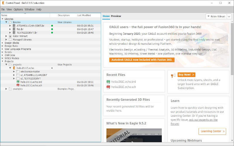
Installed libraries in EAGLE
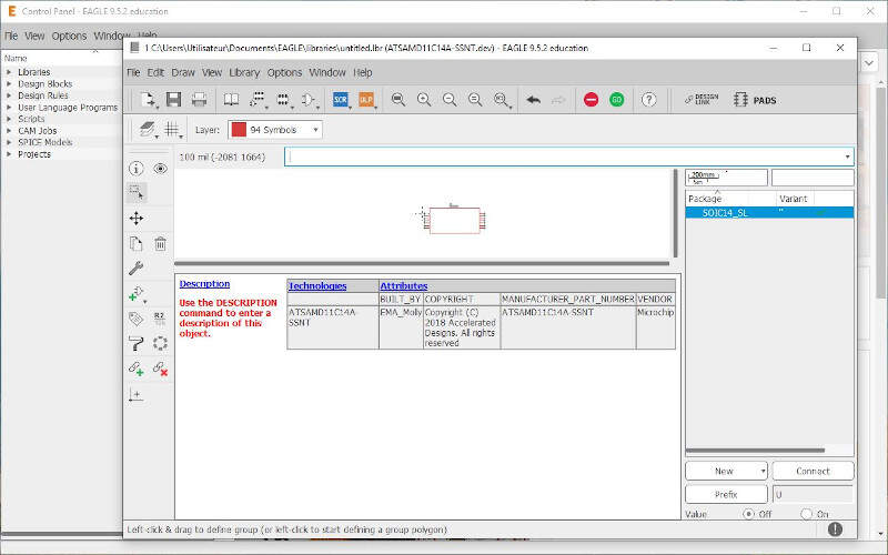
As an example I chose to explain how I added the ATSAMD11C14A-SSNT library. First I typed "ATSAMD11C14A" in the google search bar and I followed a link to Digi-Key webpage. This page provides a lot of information such as the datasheet and a link to UltraLibrarian that provides the schematic and the footprint of the component.
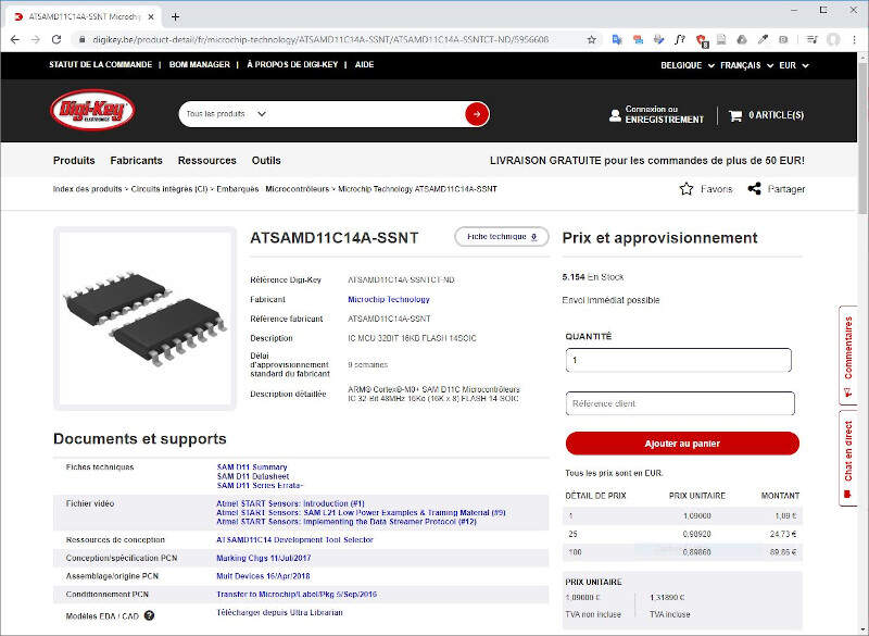
ATSAMD11C specifications on Digi-Key
On UltraLibrarian I selected the type of component and the characteristic of the schematic then I clicked on "Download Now"
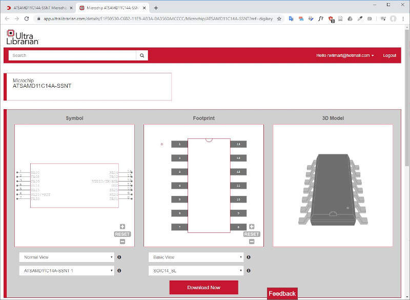
ATSAMD11C package on UltraLibrarian
Then I selected the Eagle format. I also selected the 3D CAD Model and the KICAD format for later use.
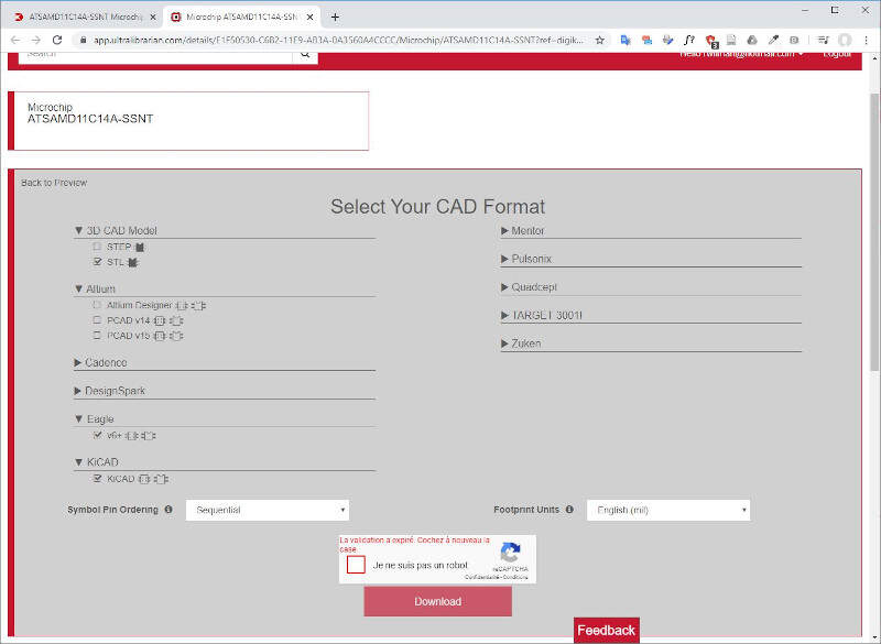
Download the ATSAMD11C package on UltraLibrarian
In EAGLE I selected "File -> New -> Library" and in the Library Manager I selected "File -> Execute Script...". In the popup window I browsed the file downloaded with UltraLibrarian then I saved the library. As I already said I made sure later that the green circle next to the library name was active for all projects.
Add the library to EAGLE
To draw a PCB board in EAGLE I first created a new project: "File -> New -> Project". Then in the project folder I created a new schematic file: "File -> New -> Schematic". In the schematic window, I click on "Add Part" icon, I navigated in the libraries and chose the ATSAMD11C14A.
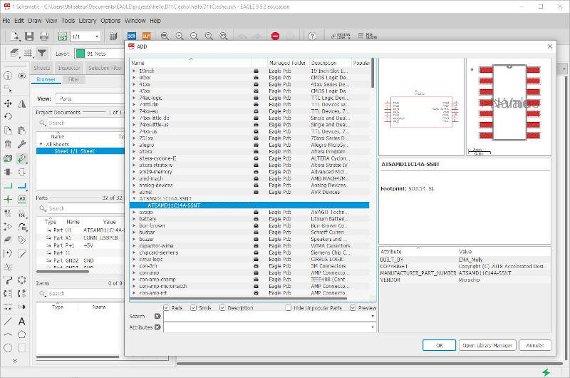
Add part in the schematic window
After clicking OK drop the component at the place you want.
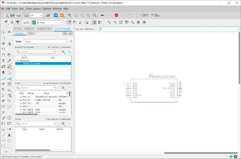
Drop the component where you want to place it
I also added the JTAG connector and I used the "Net" tool to make connections between the components.
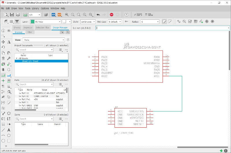
Make the connections with the "Net" tool
Hereinafter is the final result of my board schematic in EAGLE. I was then ready to go for the next step: the board design.
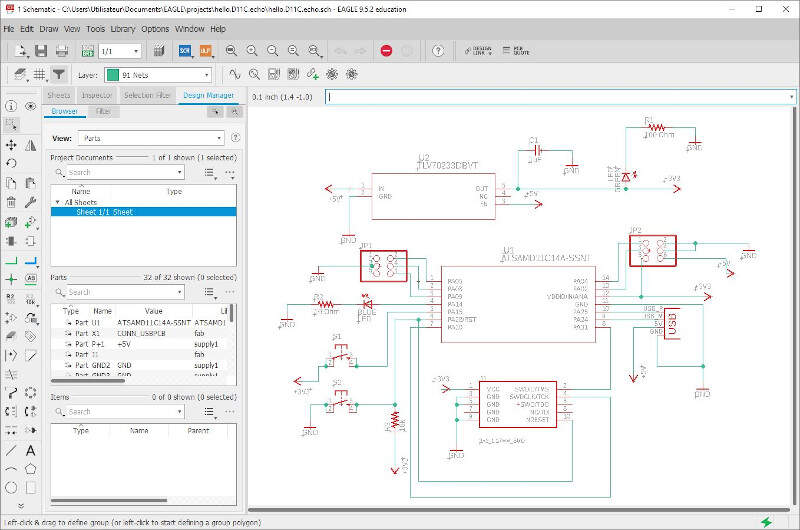
My board final schematic
The board design was the least easy part of the job. When I created the new board file (from the schematic window: "File -> Switch to board") all the component footprints were placed randomly in the board window.
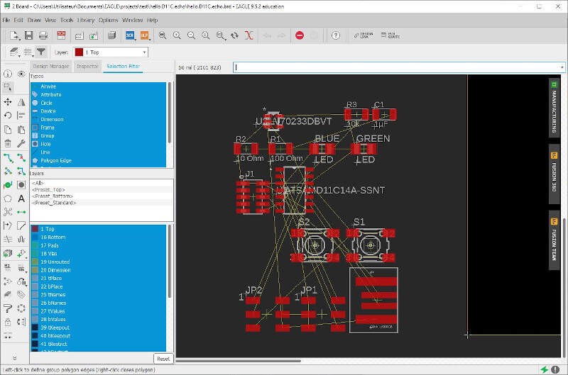
EAGLE rhymes with puzzle
I took 5 hours to place, rotate, link, unlink and move the component again and again to finally reach a satisfying result where no trace cross each other in a pretty compact way. A perfect job for someone who loves puzzles.
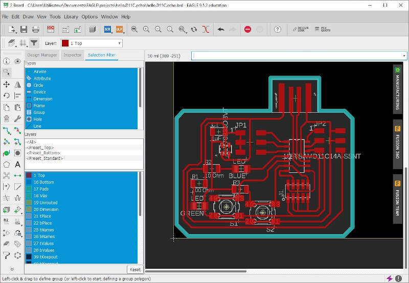
My final board design
I used a different layer to draw the lines for cutting the board edges by selecting the "45 Milling" Layer in the scrolling menu.
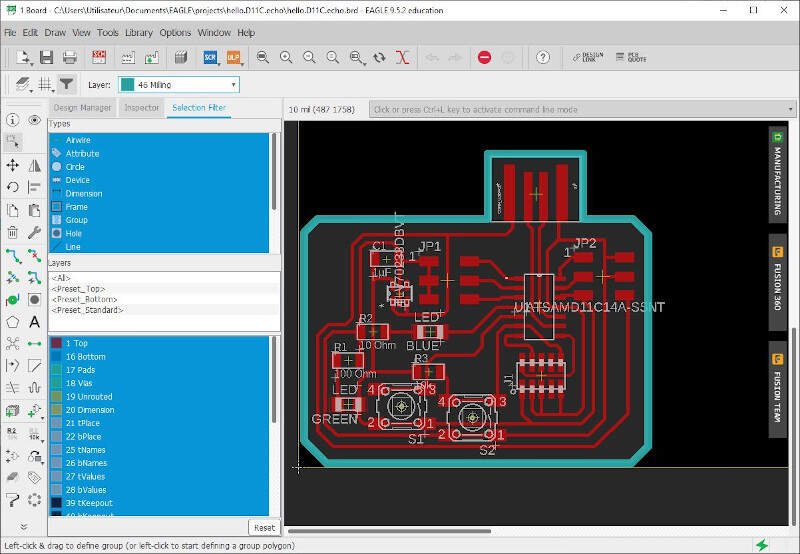
Select the "45 Milling" layer for cutting the board edges
I also used the "DRC clearance" tool to check if there were mistakes in the board. To do that I entered the settings shown in the following picture and I clicked the "check" button.
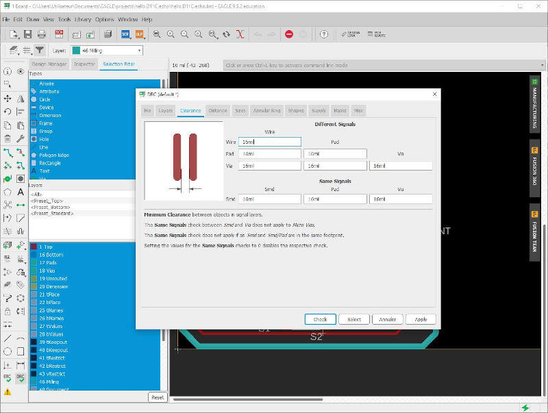
Use the DRC clearance to check the board and rise possible errors
Once the errors corrected my file was ready for printing. I first printed a paper version of my board to quickly check that the footprints were good enough to receive the electronic components. As it was alright the file was ready for production.
Bantam
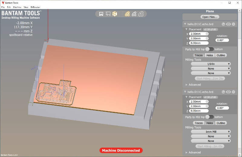
To produce the board I used the Bantam Tools Desktop PCB Milling Machine. Since its user interface is compatible with EAGLE I directly imported the "hello.D11C.echo.brd" file in Bantam Tools.
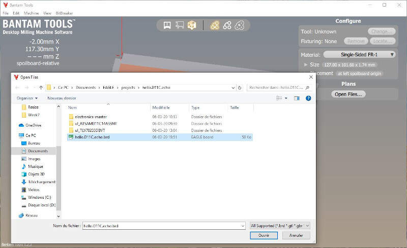
The EAGLE file imported into Bantam
I imported it twice: once for milling the traces with a 1/64" End Flat Mill and once for cutting the board sides with a 1mm End Flat Mill.
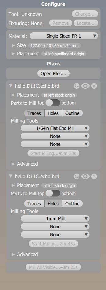
For the first file only "traces" is selected and for the second file "holes" is selected
As the time for milling the board was ridiculously slow when selecting the Bantam default End Flat Mills (45 minutes 34 seconds) I created new tools in "File -> Tool Library...". For these tools I set higher feed and plunge rates, a higher spindle speed, a smaller stepover (25%) and a pass depth of 0.08mm for the 1/64" End Flat Mill such that the Bantam would remove the copper layer in two passes. This helped to reduce the milling time to 21 minutes 29 seconds. For the 1mm End Flat Mill I put the same parameters than the previous tool except for the pass depth that I set to 0.87mm: the half of the PCB board thickness such that the milling machine would cut the board in two passes.
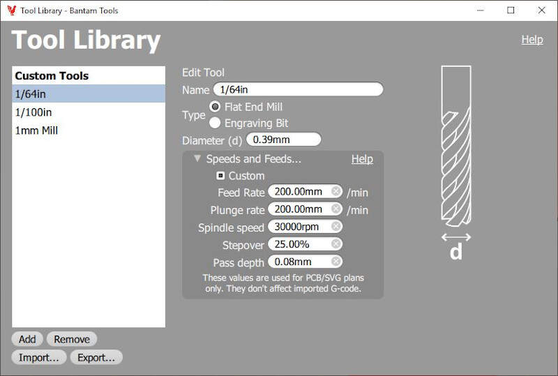
Settings of the custom tools in Bantam
In total it took 24 minutes and 14 seconds to produce the PCB board. But yet it had to be stuffed with all the different electronic components.
Rendering and time estimation of the milling in Bantam
The following pictures shows the result after the milling.
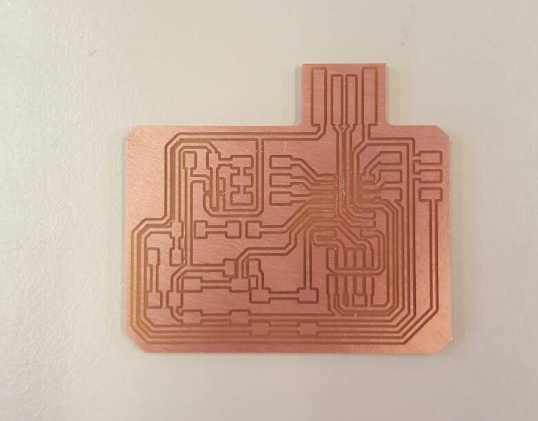
PCB board after milling
Hereinafter is a picture of the board after the soldering. With a multimeter I made sure that there was no electrical short-circuit. With such small components like the voltage regulator where the traces are very close to each other, it is easy to make unintended bridges between traces. And in fact I had made one bridge between the ground and the 5V power supply of the regulator. To solve that I added a small drop of flux paste on the solder bridge and I heated it. In less than 2 seconds the solder melted. This process spread smoothly the solder excess on the traces like water and therefore disrupted the bridge.
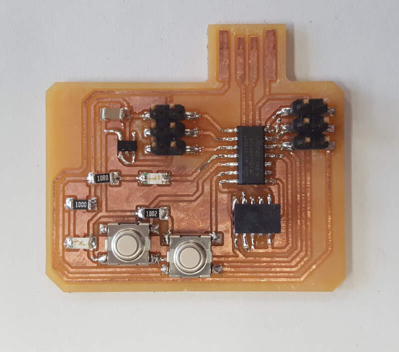
PCB board after soldering
Programming
Now that all the electronic components stood on my board I had to test it. I wanted to make sure that the reset button, the button on pin PA15 and the LED on pin PA14 were working. An encouraging observation was that when I plugged the USB connector in my laptop I saw the green LED lighting up, as expected.
EDGB
With EDBG I uploaded a USB bootloader on my board through the JTAG connector via the particle debugger. I found the USB bootloader in the archive of this GitHub page.
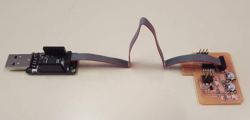
JTAG connection between the programmer and my PCB board
In the command line interface of Windows I changed the current directory to be located where both the EDBG executable file (edbg-b74-WINDOWS-7029fc4.exe) and the binary file (sam_ba_Generic_D11C14A_SAMD11C14A.bin) stood than I executed this command : "edbg-b74-WINDOWS-7029fc4.exe -e -t samd11 -bpv -f sam_ba_Generic_D11C14A_SAMD11C14A.bin".
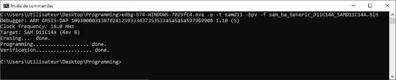
Windows command line interface when uploading the USB bootloader with EDGB
As the figure shows the USB bootloader was successfully uploaded in my ATSAMD11C14A. An another observation that confirmed that statement was that Windows was able to recognize my board when I plugged it in a USB port of my laptop.
Arduino IDE
To test the LED and buttons of my board I used the Arduino IDE. As the ATSAMD11C is not a standard Arduino board the first thing I had to do was to provide a JSON file that defines how the IDE configures additional boards. To do it I followed this tutorial. In the menu system I selected "File -> Preferences" then in the "Additional Board Manager URLs" field I added this .JSON file URL. Then I clicked on "Tools" menu and then "Board -> Boards Manager" to install "MattairTech SAM D|L|C Core for Arduino." More information about the procedure can be found here.
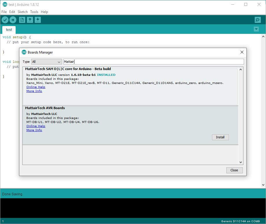
Board manager in Arduino IDE
Afterwards I used the standard Arduino Blink sketch as a start to test the capabilities of my board and I modified it. At the top of the script I declared four variables: "LED", "BUTTON", "val" and "message" that respectively represents the blue LED pin number, the button pin number, a value that will be taken by pin 15 and a string message that will be read on the serial port. In the "void setup()" function I setup the serial communication and I declared the pin mode of the LED and button. The LED is an output and the button is an input. After that I wrote a FOR loop to make the LED blinking 5 times when the board initializes.
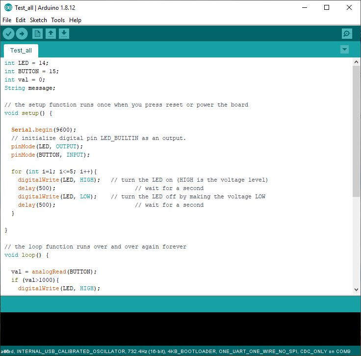
Arduino code - part 1
In the "void loop()" function the pin 15 analog value is read. Depending on that value the LED is turned on or off. Afterwards the value is printed on the serial port. After, if the serial is available, meaning if a communication is detected on the serial port, then the message is read, stored in the "message" string and printed back on the serial port. This procedure is repeated approximatively every single second.
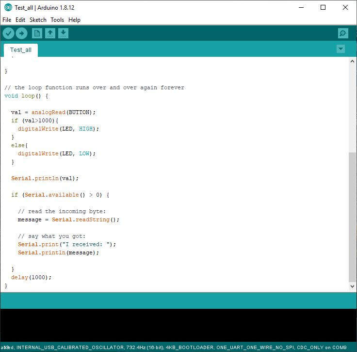
Arduino code - part 2
With my code I was able to alternately turn on and off five times the BLUE LED on PIN PA14 directly after the board received power or when the RESET button was pressed. I could also use the button on PIN PA15 to turn on the LED by pressing it and send the analog value red on that pin to the serial port.
Testing of my PCB board