6. 3D Scanning and printing
Ultimake 3 Extended
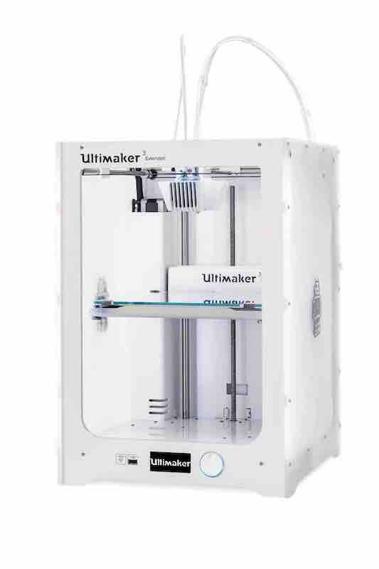
The Ultimaker 3 Extended is capable of 3D printing with PLA, PVA, ABS, CPE and Nylon filaments. The Ultimaker 3 Extended offers a very high 3D printing resolution and uses 2.85 – 3 mm diameter filament. Compared to its predecessor the Ultimaker 3 Extended offers a lot of new features, including A dual extruder head which allows the Ultimaker 3 to produce dual material 3D prints; in multi materials (such as PVA and PLA) or multi color 3D prints. The PVA is especially useful for support material when printing complex shapes that require support. It’s easy to remove, you just put it in a bowl of water and it melts away. It also has a camera built in that allows users to monitor their 3D prints directly from a different location.
Ultimaker 3 Extended Tech Specs - Build volume of 215 x 215 x 300 mm. - Layer resolution up to 20 micron for 0.4 mm nozzle. - Print temperature up to 280 ˚C. - Dual extrusion with a soluble support material. - Heated build plate with active levelling. - Materials: Thermoplastics (PLA, ABS…)
I was looking forward to this week because as a designer, I wanted to know more about the limitations and advantages of 3D printing. It’s helpful for prototyping organic, flexible, and complex shapes. It’s also more accurate as a prototype modelling option when compared to the original design. My previous prototyping methods were using foam or wood, and it was hard to get the final to look like the original 3D design when done by hand. 3D printing is more time efficient as well. It also reduces waste because you only use the amount of material your design needs, instead of cutting away materials like other manufacturing processes.
Some of the limitations is the long time it takes to finish prints, build size is small, and materials are limited. The most common option is PLA, which is what I used. It gives great results but can be restrictive if you’re looking for a different finish than plastic. It’s also hard to recycle and required high temperatures for the material to biodegrade. It’s also expensive; in the lab we have access to a lot of material options and colors, but for personal use it would cost a lot to use it consistently.
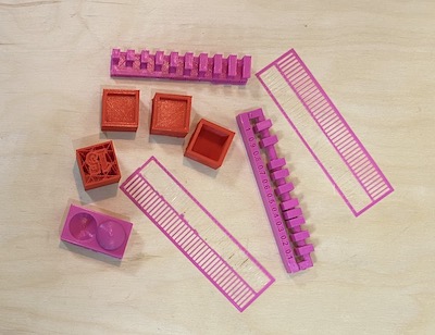
Group Project
For this week’s group project, we each used the 3D printer to test different design rules like clearance, infill, overhang, and bridging. I worked on the overhang and 3DBenchy.
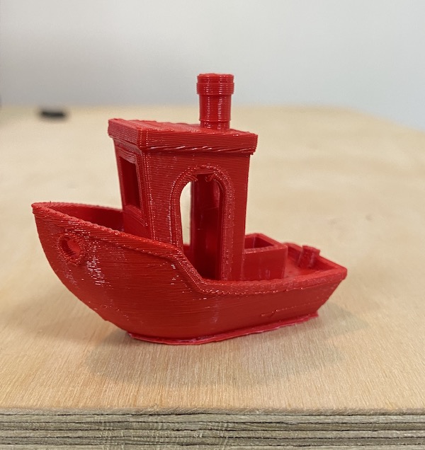
3DBenchy
I tested the accuracy of our printer using 3DBenchy by Creative Tools. The name ‘Benchy’ is short for benchmark, it’s designed with geometric features, such as the portholes and an open cabin, that provide a challenge to 3D printers. When using a new filament, or 3D printer, the 3DBenchy can be used to see how they measure up. For more information on 3DBenchy, visit this link.
Since this was my first time using a 3D printer, I decided to begin with this test because it gave a more general overview of the final outcome.
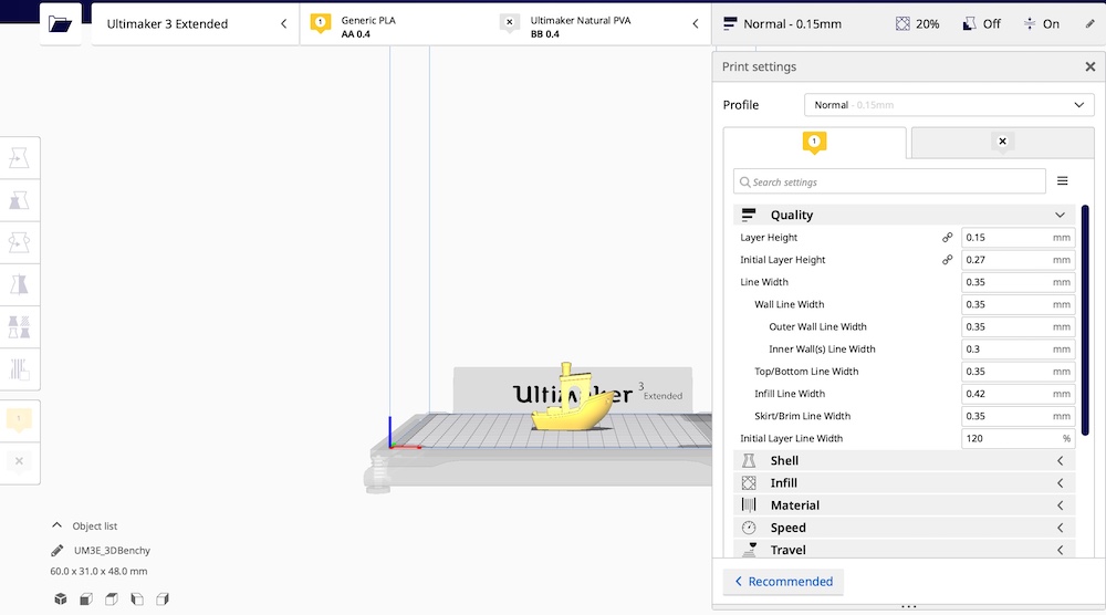
After downloading the file, the next step was to slice it using Cura. The steps were:
-
Open the STL file in cura
-
Select the printer (Ultimaker 3 Extended). Then select material: PLA 0.4. Deselect the second nozzle, which is often used for support, because the aim here is to test our printers limit. Change the print profile to normal (0.15mm). Keep the infill density as is (20 % triangle pattern).
-
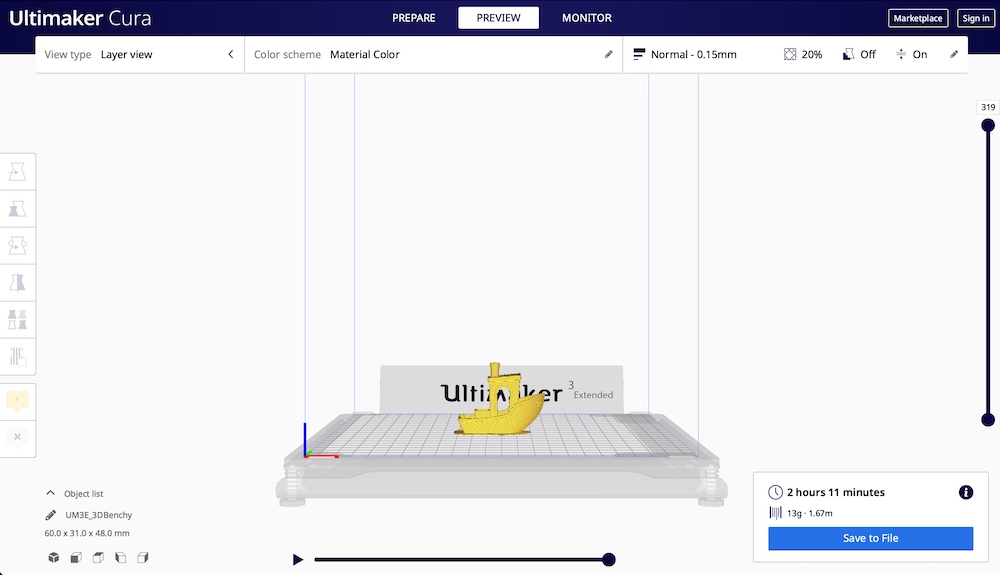
Once all settings final, click the slice tab to get a calculation of the estimated time to print + a preview of how the printer will complete the print.
I then exported the file to my flash drive, loaded the material (PLA), calibrated the build plate, and inserted the flash drive in the 3D printer to begin the printing process.
To ensure filament adhesion to the build plate, we have to calibrate the build plate level. In our lab we used manual levelling following the below steps:
- In your 3D printer, go to system > build plate > manual levelling.
- Rotate and adjust all the knurled fasteners clockwise until it is tightened all the way.
- Rotate the button at the front until the plate is approximately 1 mm from the nozzle.
- Place a piece of A4 paper between the nozzle and the plate, unscrew the fastener until a bit of resistance is felt.
- Click on confirm, and repeat step 4 for the left and right sides.
For a more detailed step-by-step guide you can use this link as a guide. The machine takes you through the steps one by one.
Result: Overall, this was a good way to know the quality of print if the general/normal settings are used. I expected the layers to be less visible, it was clear that to get a better print moving forward it’s best to have the layer heigh settings from 0.06 to 0.1.
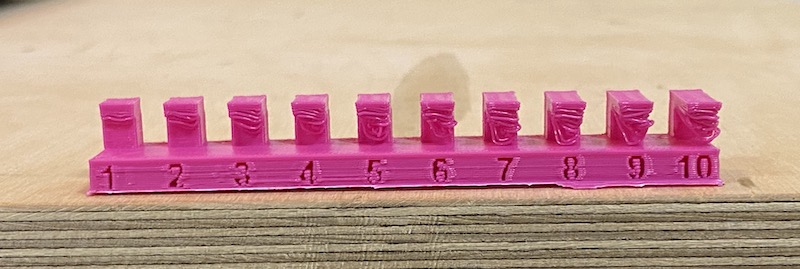
Overhang
I downloaded the STL file from the (3D scanning and printing page](http://academy.cba.mit.edu/classes/scanning_printing/index.html_ from the Fab Academy class website.
I used the same settings and followed the same step as in the previous test. It’s important to not to use the second nozzle to get a better idea of our printers limits with overhangs.
Result: It’s clear that with our printer we need support if our design includes overhangs even with small (1mm) overhangs.
Individual Project:
Design
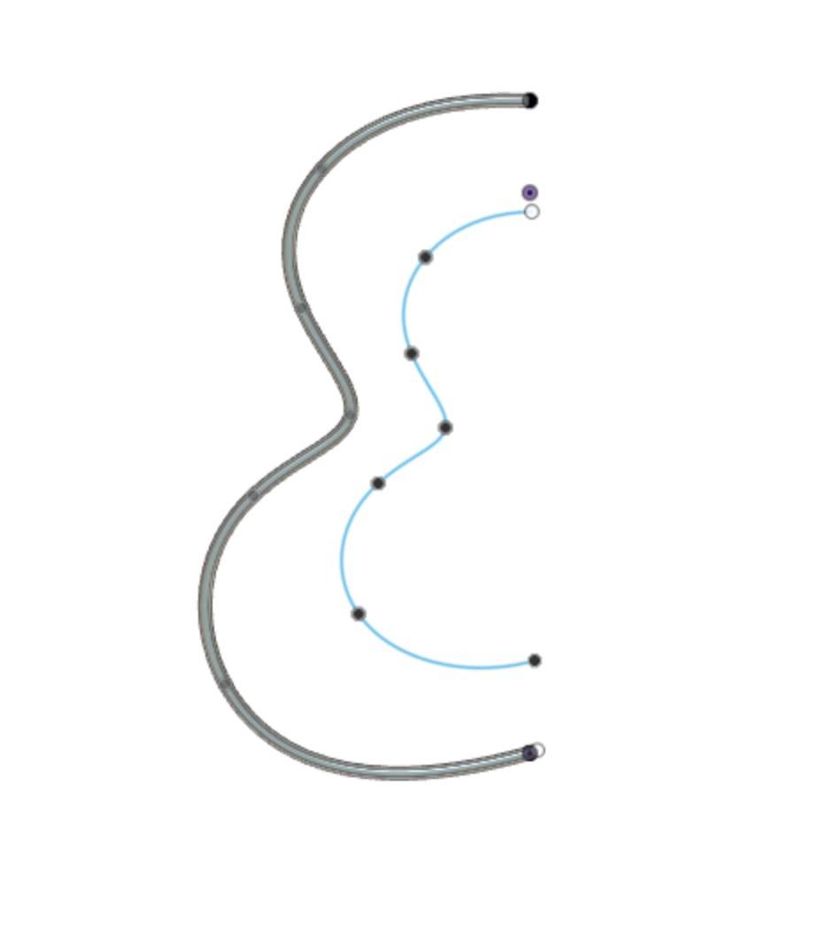
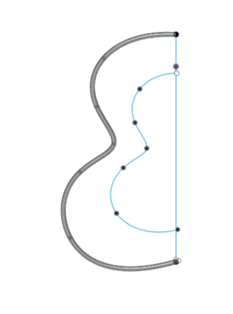
I experimented with different lines that led to a pear shaped skeleton. I then offset the skeleton inwards to have a moving sculpture. I chose this shape because a main requirement for this assignment is to use additive manufacturing to create an object that cannot be created using subtractive manufacturing. This design qualifies for this assignment because if I had to do it with another process, it wouldn’t be possible to make it as one object and would have to be multiple parts connected together. We have to have one object that has an element that makes it uniquely producible using a 3D printer in one go only.
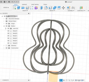
I started by inserting the pear shape in two size, one will be the outer shape and the smaller shape will revolve inside.
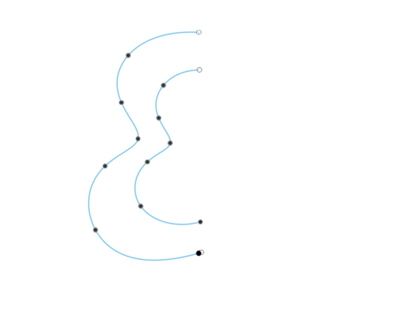
I used the sweep tool to create the outer pear, then sketched the central line and applied the same sweep command
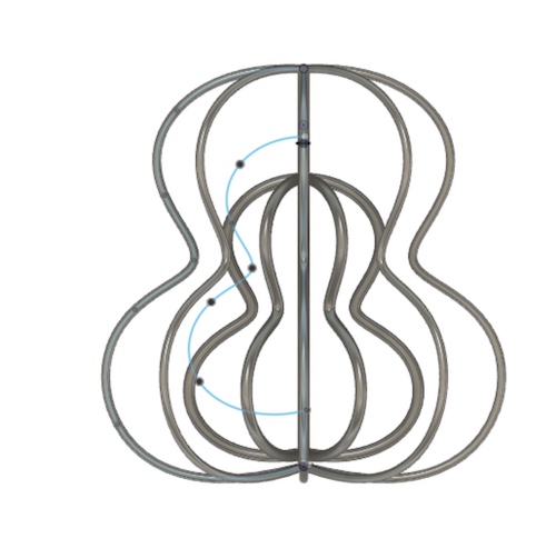
For the revolving shape, I created a circular pattern using the outer pear body
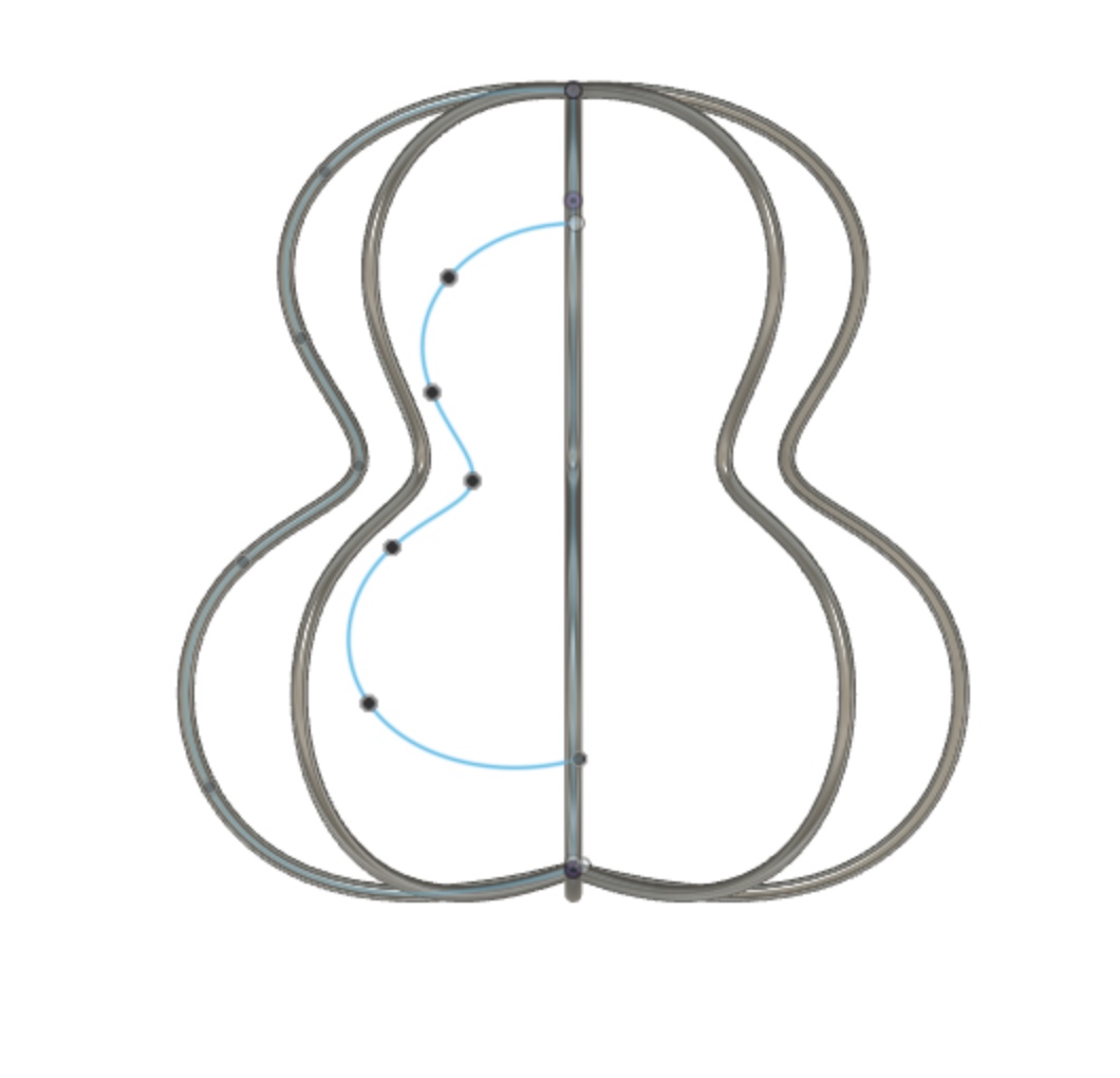
I repeated the same process to the inner pear shape and moved it closer to the bottom to avoid using too many infills when printing
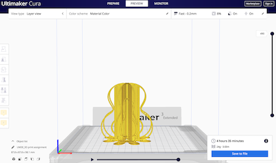
I then exported the STL file and opened it in Cura, I started out using the same settings as the group assignment (mentioned above). I then changed the layer height to fast and the infil to 8% to reduce the total time from 7 hours to 4:35 hours. I knew this would sacrifice quality, but I used this as an additional testing opportunity to know what the final outcome would be with a different more fragile design.
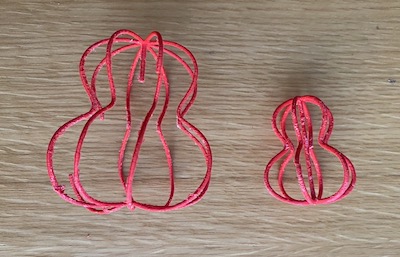
In the settings, I chose the support to be the same PLA material. However, I stopped the printing shortly after starting because I have light overhangs in my design and will not be able to remove the support without breaking the model.
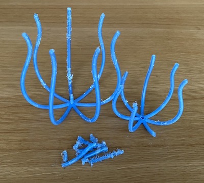
I changed the support to PVA instead of PLA and changed the thickness to (4mm), unfortunately, that was still too thin for the printer.
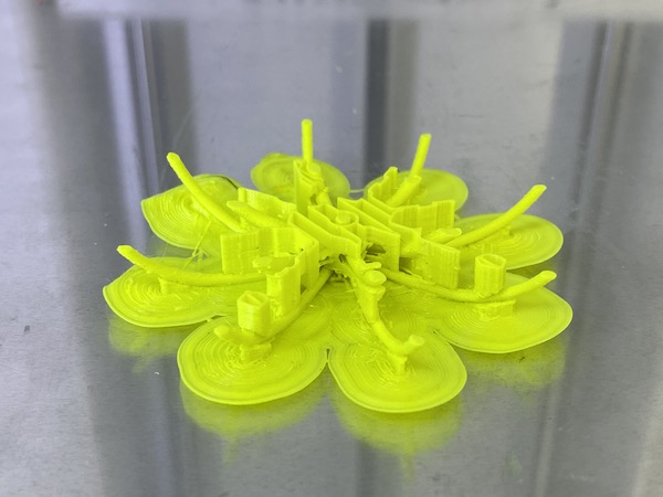
For my third attempt, I changed the design to be open, increased the thickness to 8mm and increased the size. It still had the same concept (and object moving inside an object) but a different shape. Unlike the previous two design, the shape was solid but there was an error in the printer that wasn’t visible until the end after soaking it in water.
Second Design:
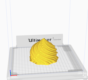
I also created the below shape using Rhino. This shape can be done using subtractive manufacturing and therefore was not applicable to this assignment.
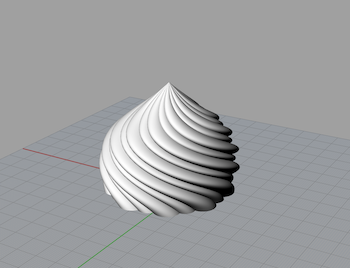
I used the same printer and setting as above except for the layer height (I used 0.1). To increase the printing speed, I increased the infill speed and decreased the thickness to 8%. It wasn’t a big change and only reduced the printing time to 5.5 hours instead of 6 .
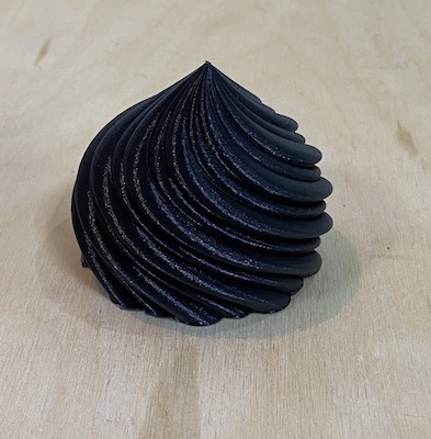
Final design
3D Scanning
I started trying the 3D Systems Cubify Sense Scanner available in the lab, but it was not accurate, and took a long time to process. It was also it was difficult to process all sides with it and keep a steady hand.
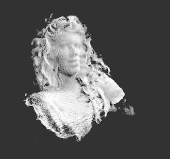
3D scanning works by placing an object (or person) and scanning all sides. I was trying to scan people, eventually myself with the help of Fatima, but it was hard to capture all sides with a semi decent outcome. My second attempt was to use Capture 3D mobile application, however, it didn’t work so well and I couldn’t fill in the gaps in order to eventually 3D print the scan.
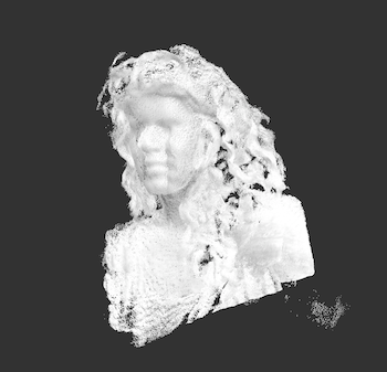
The process was simple, I used the app and asked a friend to take the scan while I was sitting still.
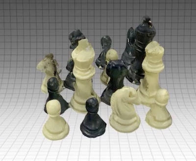
Another application, Capture, works better but it needed a specific camera sensor attached to work that I didn’t have. I scanned the below chess pieces using the mobile application Qclone using the same process as Capture 3D:
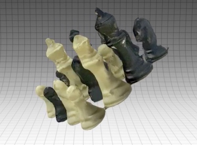
My experience using 3D scanning was not as expected - it wasn’t accurate at all. It was also very difficult to find a scanner that was good and not expensive. It is an exciting technology, you can scan anything from your environment and reproduce it. I wanted to take this a step further and try scanning plants and flowers, but sadly the test I completed for this assignment wasn’t very encouraging.