16. Interface and application programming
Group Assignment
Compare as many tool options as possible.
please check the group assignment here.
Individual Assignment
Write an application that interfaces a user with an input &/or output device that you made.
Processing
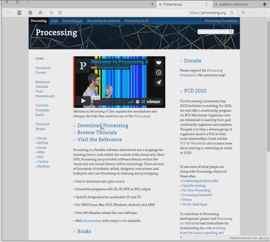
For this week’s assignment I started by downloading the software “Processing” which is a flexible software sketchbook and a language for learning how to code within the context of the visual arts. You can download the software from this website.
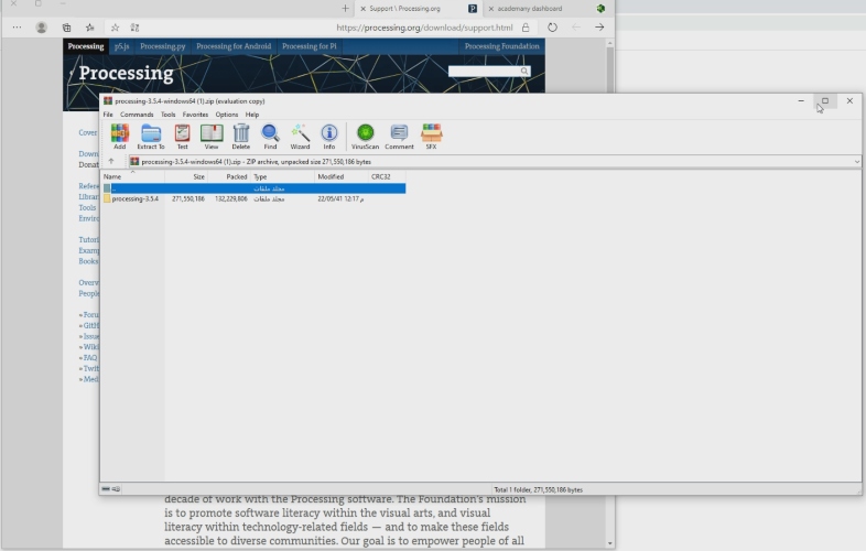
I download the software that is compatible with my laptop which is 64-bit and I after it finished downloading I extracted the files.
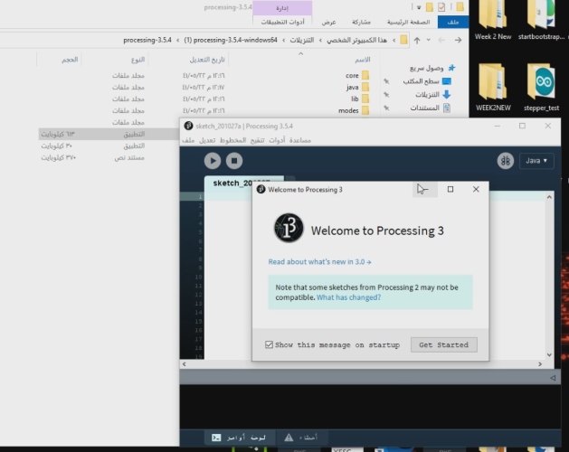
After extracting the file I opened the software.
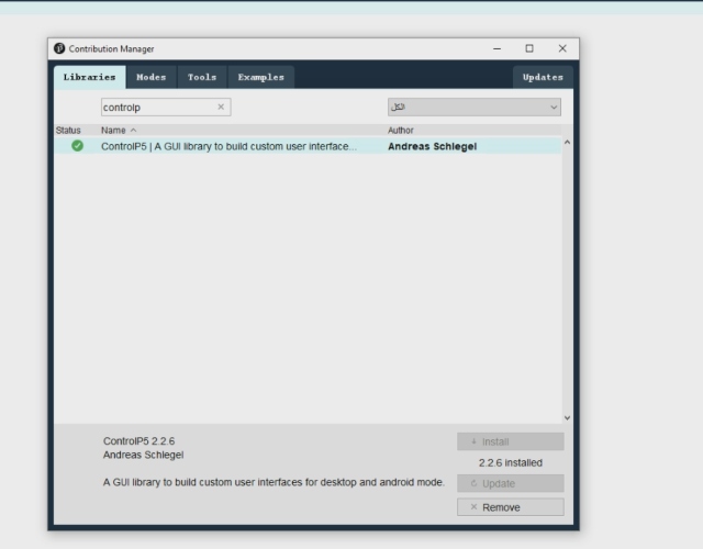
Now I clicked on “Sketches” then “Import Library” and then “Add Library”.
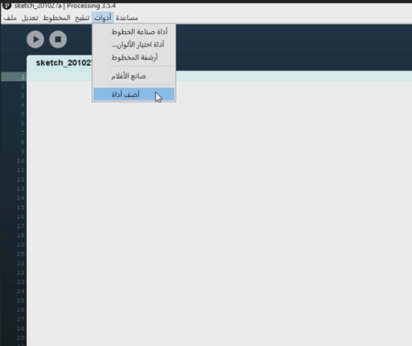
I typed “controlp5” and chose the library that I will use for this project and then I clicked on install to use it.
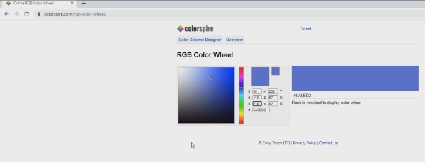
Now I google searched a website that will give me the color shades I want for the LED light on my Arduino board.
The color I used is blue and the inputs are R:90 G:110 B:210. These numbers will be inputted on the Processing software to make the background blue.
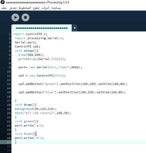
These are the codes that I used for the Processing software.
First, we import the libraries we are using: the control P5 library which generates the graphics, and the processing.serial library which connects to the Arduino. Then we call the serial port with the correct number. I created the box in the size I want, Then I added two buttons with the .addbutton function, and set their labels, position and size. Then in the void Draw loop, I set the background color of the box, and I added a title to the box. Then I am calling the two function for the buttons, so that when the button labelled green is pressed, it sends the letter ‘g’ on the serial connection, and when the button labelled blue is pressed, then it sends the letter ‘b’ on the serial connection.
import controlP5.*;
 import processing.serial.*;
 Serial port;
 ControlP5 cp5;
 void setup(){
   size(500,400); // creating the background by calling both the size and background function
   printArray(Serial.list());

   port= new Serial(this,"com7",9600);

   cp5 = new ControlP5(this);

   cp5.addButton("green").setPosition(100,100).setSize(100,80); // add green button

   cp5.addButton("blue").setPosition(100,250).setSize(100,80); // add blue button

 }
 void draw(){
 background(90,110,210);
 text("Ali LED Control",100,30); // adding a title to my window calling text function:
 }
 void green(){
 port.write('g');  // g character will be sent once green button is pressed
 }
 void blue(){
 port.write('b'); // b character will be sent once blue button is pressed

 }
Arduino
Now I opened the Arduino software and inputted these codes.
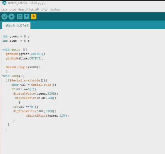
In this code we will use the pins of Arduino and Pin number 9 will be blue while Pin number 8 will be green. When I click on the button which I called “Blue” on the Processing window the Blue LED will turn on and when I click the other button which is called “Green” the Blue LED will turn off and the Green LED will turn on.
 int green = 8 ;
 int blue  = 9 ;

 void setup (){
   pinMode(green,OUTPUT); // is used to configure the pin 08 to behave either as an output.
   pinMode(blue,OUTPUT); // is used to configure the pin 09 to behave either as an output

   Serial.begin(9600);  // data rate in bits per second (baud) for serial data transmission
   }
 void loop(){ // check serial communication
   if(Serial.available()){
      char val = Serial.read();
      if(val == 'g'){

       digitalWrite(green,HIGH);   // turn green LED strip ON
       digitalWrite(blue,LOW);  // turn blue LED strip ON

          }
       if(val == 'b'){
       digitalWrite(blue,HIGH);
       digitalWrite(green,LOW);


       }
    }
  }
Here is the hero shot of the final product.
This week I was not present so Maha explained everthing to me and here is her website
Second application using my own PCB:
for this time i will use my atemga 328p board to control the RGB LEDs, I did mill a new board because the old one was damaged the FTDI cable was not working. now I can use FTDI cable to upload programs in my board. so I did use for this assignment
Processing code:
For the Processing code I use the same code as the first application i did in the Assignment above while controlling the leds, I have the same interface two buttons to change between the green and blue.
import controlP5.*;
 import processing.serial.*;
 Serial port;
 ControlP5 cp5;
 void setup(){
   size(500,400);  // creating the background by calling both the size and background function
   printArray(Serial.list());

   port= new Serial(this,"com3",9600);

   cp5 = new ControlP5(this);

   cp5.addButton("green").setPosition(100,100).setSize(200,100);  // add green button

   cp5.addButton("blue").setPosition(100,250).setSize(200,100);   // add blue button

 }
 void draw(){
 background(90,110,210);
 text("Ali  RGB LED Control",100,30); // adding a title to my window calling text function:
 }
 void green(){
 port.write('g'); // g character will be sent once green button is pressed
 }
 void blue(){
 port.write('b');  // b character will be sent once blue button is pressed

 }
Arduino Code:
I used the example code found Adafruit NeoPixel library which I download it, so I can control the RGB. To control the RGB I need only 3 pins VCC, GND, and, the signal pin is connected to pin PD3 so I did edit the code and change the signal pin to pin 3 for Arduino.
#include <Adafruit_NeoPixel.h>
#ifdef __AVR__
  #include <avr/power.h>
#endif

#define PIN 3

// Parameter 1 = number of pixels in strip
// Parameter 2 = Arduino pin number (most are valid)
// Parameter 3 = pixel type flags, add together as needed:
//   NEO_KHZ800  800 KHz bitstream (most NeoPixel products w/WS2812 LEDs)
//   NEO_KHZ400  400 KHz (classic 'v1' (not v2) FLORA pixels, WS2811 drivers)
//   NEO_GRB     Pixels are wired for GRB bitstream (most NeoPixel products)
//   NEO_RGB     Pixels are wired for RGB bitstream (v1 FLORA pixels, not v2)
//   NEO_RGBW    Pixels are wired for RGBW bitstream (NeoPixel RGBW products)
Adafruit_NeoPixel strip = Adafruit_NeoPixel(60, PIN, NEO_GRB + NEO_KHZ800);

// IMPORTANT: To reduce NeoPixel burnout risk, add 1000 uF capacitor across
// pixel power leads, add 300 - 500 Ohm resistor on first pixel's data input
// and minimize distance between Arduino and first pixel.  Avoid connecting
// on a live circuit...if you must, connect GND first.

void setup() {
  // This is for Trinket 5V 16MHz, you can remove these three lines if you are not using a Trinket
  #if defined (__AVR_ATtiny85__)
    if (F_CPU == 16000000) clock_prescale_set(clock_div_1);
  #endif
  // End of trinket special code

  strip.begin();
  strip.setBrightness(50);
  strip.show(); // Initialize all pixels to 'off'
  Serial.begin(9600);
}

void loop() {
  // Some example procedures showing how to display to the pixels:


   if(Serial.available()){
      char val = Serial.read();
      if(val == 'g'){

       colorWipe(strip.Color(0, 255, 0), 50); // Green

          }
       if(val == 'b'){
       colorWipe(strip.Color(0, 0, 255), 50); // Blue

       }
    }

}

// Fill the dots one after the other with a color
void colorWipe(uint32_t c, uint8_t wait) {
  for(uint16_t i=0; i<strip.numPixels(); i++) {
    strip.setPixelColor(i, c);
    strip.show();
    delay(wait);
  }
}

// Input a value 0 to 255 to get a color value.
// The colours are a transition r - g - b - back to r.
uint32_t Wheel(byte WheelPos) {
  WheelPos = 255 - WheelPos;
  if(WheelPos < 85) {
    return strip.Color(255 - WheelPos * 3, 0, WheelPos * 3);
  }
  if(WheelPos < 170) {
    WheelPos -= 85;
    return strip.Color(0, WheelPos * 3, 255 - WheelPos * 3);
  }
  WheelPos -= 170;
  return strip.Color(WheelPos * 3, 255 - WheelPos * 3, 0);
}
Here is the hero shot:

This work is licensed under a Creative Commons Attribution 4.0 International License.