9. Embedded programming
This week I worked on programming my previously manufactured ATtiny 412 board using arduino IDE.
Group Assignment
- Compare the performance and development workflows for other architectures
Individual Assignment
ATtiny 412 Microcontroller data sheet
- From the data sheet I could Learn the following important things about the ATtiny 412:
- It is an 8 bit Microcontroller.
- It uses Harvard Architecture, i.e. It has separate bus for program and data.
- It has a RISC based CPU.
- It has 10 bit ADC.
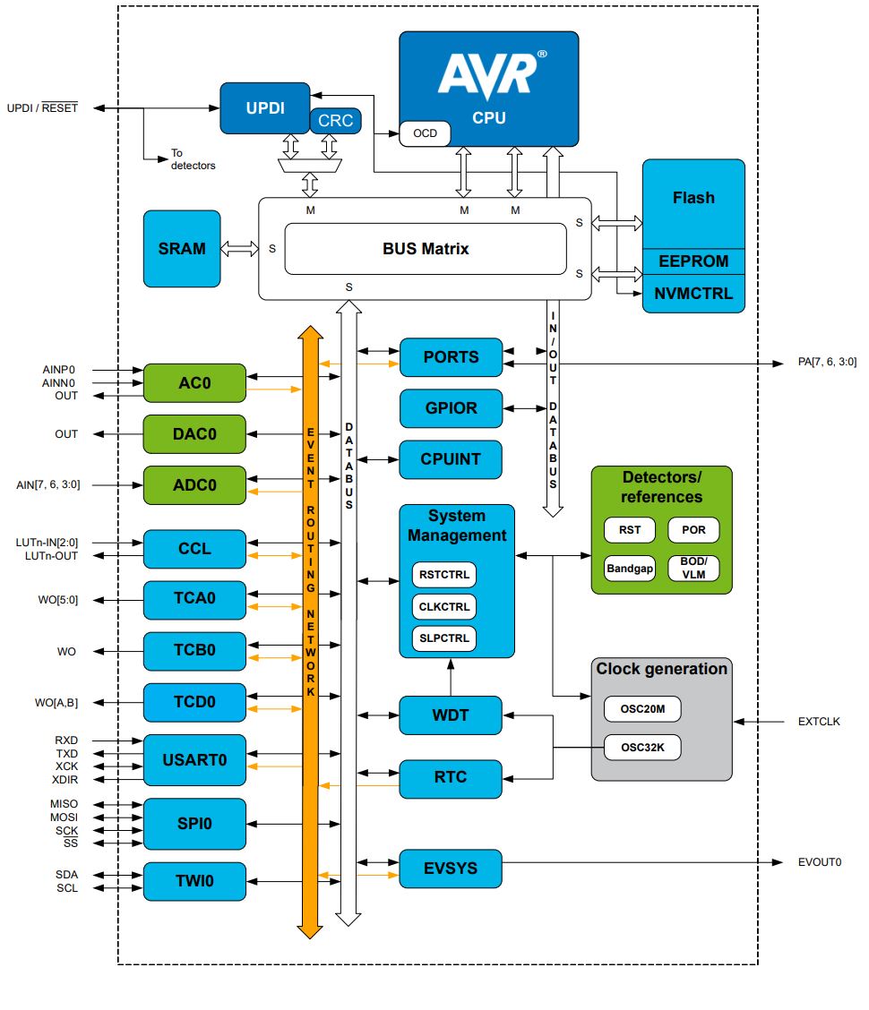 Block Diagram Source
- From the internal Block diagram I got the chance to see the different hardware available for the MCU and how they are connected.
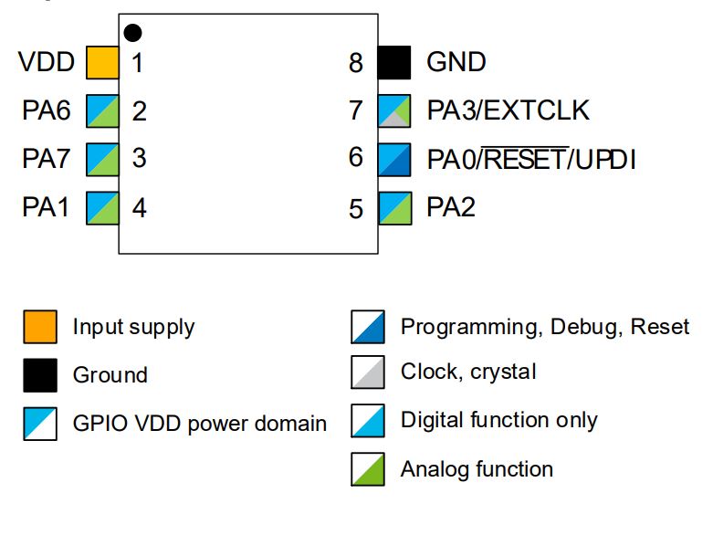 Pin Layout Source
- The pin layout of the ATtiny412 is as shown in the picture above. The programming of the board is done via UPDI on the pin number 6.
Programming ATtiny412
- First I connected My previously manufactured UPDI programmer to the ATtiny board as shown in the image. Then I opened The Arduino IDE and in Tool settings I modified the settings to look as shown in the image below.
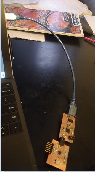 Uploading program setup
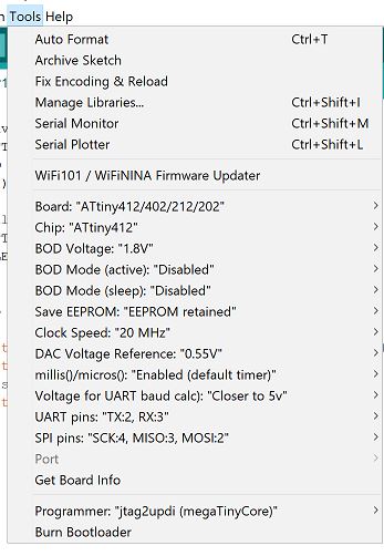 Tools setttings
- The next step was to write a program that would turn on the LED when the push button is pressed and turn it off otherwise. In order to write the program I had to define the library
which contains details about the ATtiny and that’s why the first line is #include
next define the pin names that are going to be configured. According to my schematic the pushbutton is connected to pin PA6 and the LED is connected to pin PA7. Next, I needed to configure the button as input and LED as output this explains the statements pinMode. Next notice that when the button is pressed it provides a path to ground and therefore the pin is logic ‘0’ when the button is pressed otherwise it’s pulled up by the resistor to logic ‘1’ when the button is not pressed. that’s why in my if statement the I put !(not) which makes the if statement true when Button is pressed because !‘0’=‘1’. The digitalread() statement is to check the status of the pin digitalwrite() is used to write on the pin that’s why when Button is pressed the LED is ON and when it’s not pressed the LED is OFF. After writing the program I clicked on Upload to load the program into the ATtiny MCU.
 Schematic
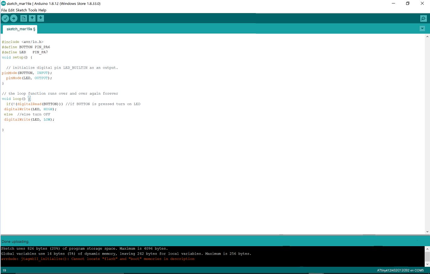 Program
Results
- The results where as expected when Button is not pressed LED is OFF and when Button is pressed the LED is ON.
Output
Group Work
In the group assignment we compared the performance and development workflows for Arduino Uno and Atmel Nucleo STM32F401 microcontrollers by making an LED-blinking test. The Group Work can be found here.