8. Computer controlled machining
This week I designed a small table in Fusion 360 and used The E2-1325 RENSI milling machine to mill it, then later I assembled it.
Table Design using Fusion 360
-
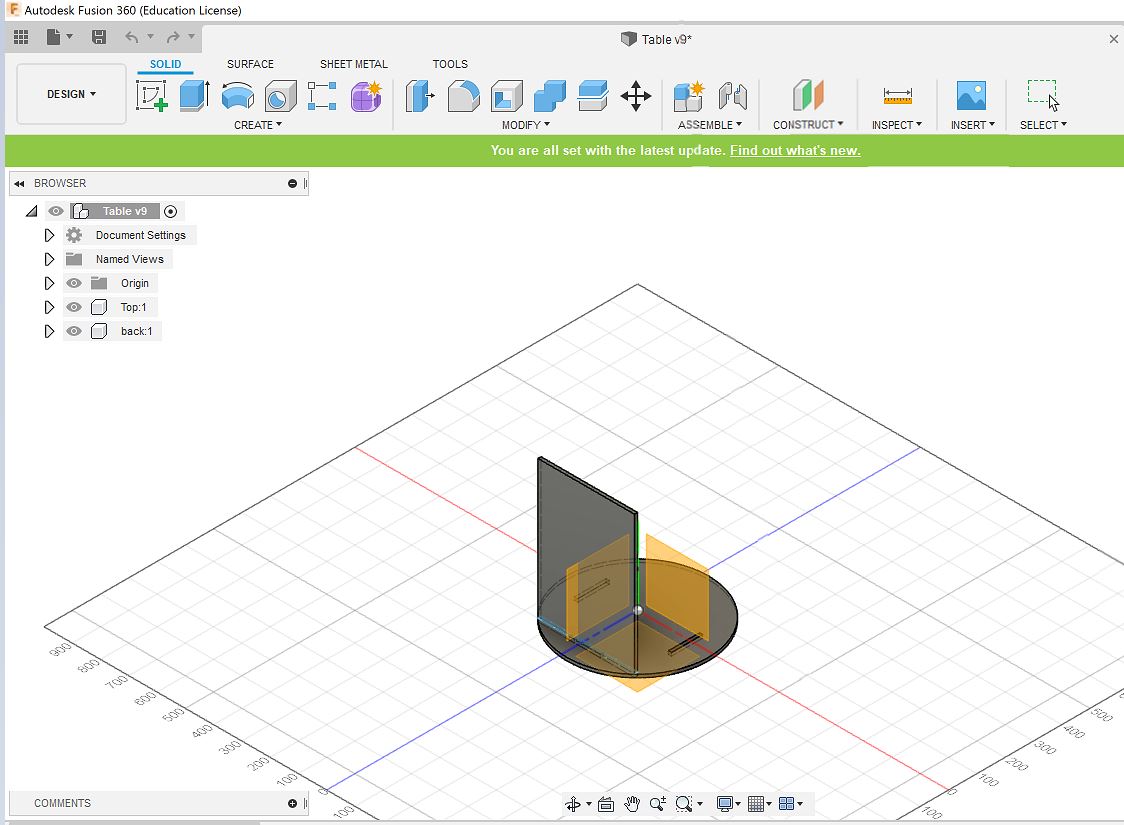
In fusion I started to design by creating the top of the table which is circular. So I drew a circle and then pulled it tothe thickness eqaual to the material to be used in milling. I also cut three openings in the top structure so as to fit the supports.
 Top of table
 -
Next, I designed the back support by drawing a rectangle and then pulling it to the desired height of the table, then I moved the structure inside the table and chose Combine to cut the support so that it fits the table opening. Similarly I did the same for the 2 remaining supports and later cut small openings where I can insert the compartments.
 Back Support
 Other parts
 -
To design the compartments I frirst created a rectangular solid on top of the supports, then I moved it down to the level of the previously cut openings and selected combine and chose the three supports as the tools to cut the compartment so that it fits in the opennings. Then, I did the same for the remaing two compartments as shown in the picture.
 Compartment
 Morecompartments
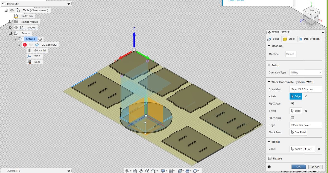
- Next I move the components and aligned them on the same axis as shown in the picture, so that it would be easy to mill them. To ensure that all the components are aligned with respect to the circular top structure, I used the option Modify> Align and then from the pop-up box I chose the component to be aligned in the from option and then chose the circular component as to in the option.
 Movecomponents
Design Setup for milling
-
The next stage was to setup the design so that it’s suitable for milling, to do that I went to Design>Manufacture from there I chose the milling tool, set the tool path for the pockets( openings in the design) and contour of the design. Finally, I created the G code for the milling machine which has all the details about my design. Everything step by step is better shown in the following images:
-
First under Setup I selected Boxpoint then as shown in the images I changed the axes orientation to match the orientation of the machine.
 Boxpoint
 Axes before
 Axes after
-
Next I chose an 8mm tool under the Tool section.
 Tool selection
 -
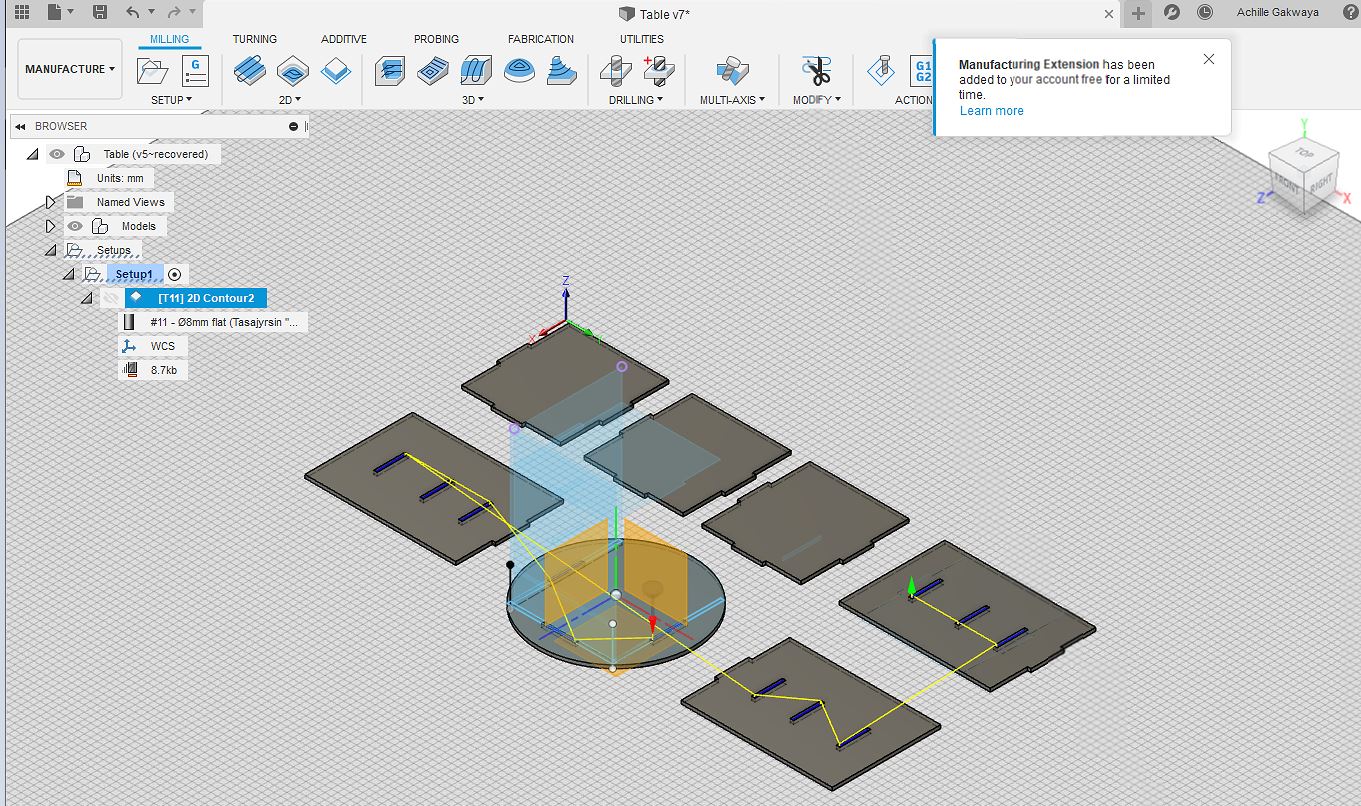
Next under countour I selected all the pockets of the design.
 Select pockets
 -
Then, I adjusted the clearance height so that the tool hovers over the design from place to place without damaging it.
 Clearanceheight
 -
In the passes settings are used to describe how the tool makes the cuts, in my case I selected even stepdowns so that it cuts evenly through the material.
 passes
 -
After all the settings were made the tool path coul be observed for the pockets.
 Toolpath for pockets
 Linking
-
Next, I selected the contour for all the objects and the remaing setup was the same as the pockets.
 Contourselection
 -
Next to simulate how the process is going to be carried out I went to Actions>simulate
 Simulation
 -
The last step was to create the Gcode for the milling machine to do this I went to Post process and uploaded the FabLabCNC file and the clicked on Post
 CreatingGcode
Manufacturing the design
-
First we measured the material to find out if it matches the dimensions of the design, then we put 6 screws (2 on the top, 2 in the middle and 2 at the bottom edges) in order to keep the material fixed during the cutting.
 Material
 -
The Milling machine is first powered by the mains switch and then turne on by using using the Power button.
 Mains switch
 Powerbutton
-
Next I opened the NC studio app which is used to control the milling machine. After the application opens a pop up that says Back to mechanical origin comes up and I selected All axes and this brings the machine to a known preset origin.
 Set mechanical origin
 -
To inspect the Tool bit I opened the screws shown in the image below and removed the red part to see if the tool was right. The tool used for the design was an 8mm Tool.
 Screws to open machine Tool part
 Inspecting toolbit
- Next, I opened my design by going to Open>Load and then selecting the directory containg the design. when the design opens in the left top corner click on the values of x and y axes origin in order to set them in the system.
 Opendesign
 Set x and y to origin
 x y origin set
- To set the Z axis a different method is used, the object shown in the image is used, it is placed directly below the tool bit and I manually lowered the tool bit using z axis inthe software by going to Options> Mobile calibrator and lowered the tool till the tool bit touched the middle of the object and after that the z axis is also set.
 Object used to set z axis
 Mobile calibrator
 Setting z origin
 Correct z origin
- Next before I started the job I first simulated the process by going to Simulate option and saw how the millin was going to be done.
 Simulate1
 Simulate2
- Next, I pressed the Dust collector button so that the dust from the removed parts is collected then the milling machine started the job.
 Dust collector button
 Milling
- After the design was fully cut I used a knife to remove it and also did some sanding to smoothen the surfaces and Finally, assembled it to get the final Table.
 Remove design
 Design parts before assembly
 Final Product
Group Work
In the group work we did Test runout, alignment, speeds, feeds, and toolpaths for the machine. the group work can be found here