
|

| Sukkur IBA University Merit, Quality, Excellence |
Week - 9
Mechanical Design, Machine Design
Group Assignment
- Design a machine that includes mechanism + actuation + automation, Build the mechanical parts and operate it manually. Actuate and automate your machine,Document the group project.
Self Balancing Robot
The task for this week is to create a machine that includes mechanisms, actuation, and automation. We considered a variety of options in light of the above requirements, with the self-balancing robot coming out on top due to its importance and benefits.
Theory of Self balancing Vehicles
A pendulum that is inverted will not be able to balance on its own. Try balancing a broom stick on your fingers as an example of this You can't stay in one place, you have to move your finger back and forth. This is exactly what the vehicle is doing, its moving back and forth so that the center of gravity will always remain under the wheels.. To drive the motors we need some information on the state of the robot. We need to know the direction the robot is falling, how much the robot has tilted and the speed with which it is falling. We'll use a combination of a gyroscopic sensor and an accelerometer to acquire this data. MPU6050 is the sensor we'll be using. We integrate all of these inputs to create a signal that controls the robot's motors and maintains it balanced.
My Role
This week, my task was to create a CAD design for a robot.
Sketch
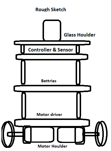
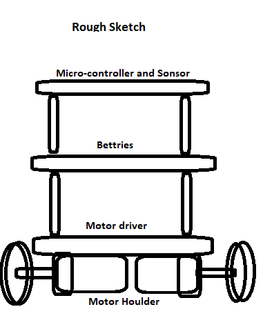
I use the MS Paint software to create my sketch because it is very user-friendly. We don't have any experience mechanical backgrounds, so before we start sketching, we go online and look up the design. Our instructor then helps us choose the design. link
Collaboration Essential
Initially, we planned to build an auto wheel balance robot capable of holding a water glass to the top floor after discussing with the instructor, and we were able to agree with the instructor that we could do this task, so it appeared that it was very easy to do, but during the design process, we realized that making the robot stable is difficult, so we did not go for the top floor.
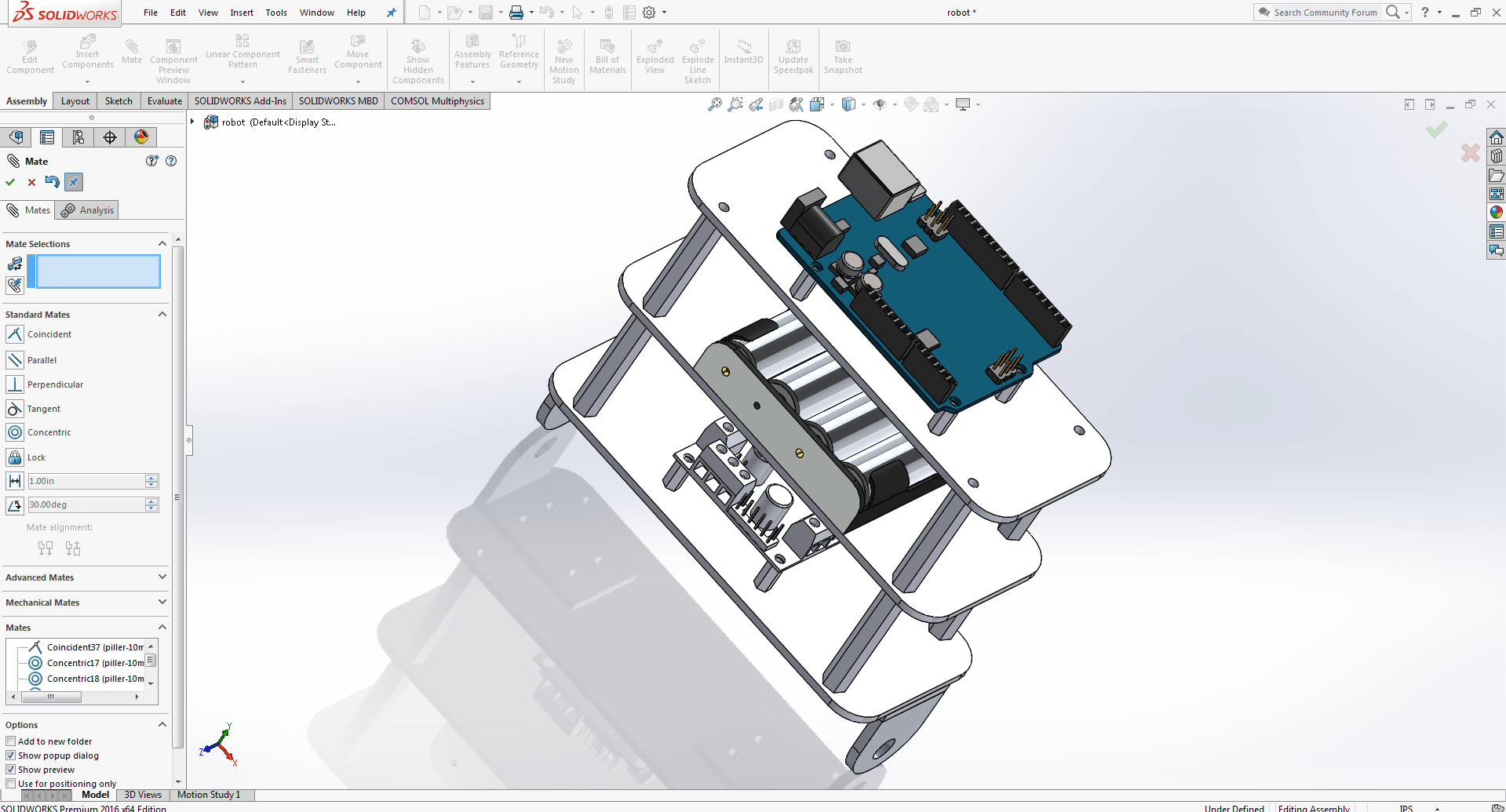
3D DESIGNING
First, we used Solid Work to design the 3D pieces for the self-balancing robot and then printed them using the Ultimaker 2+ 3D printer.
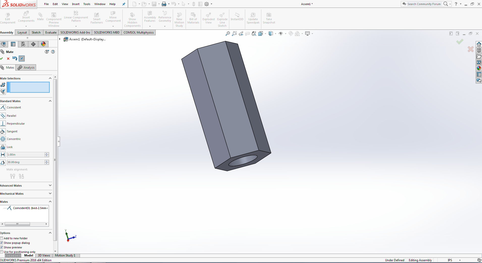
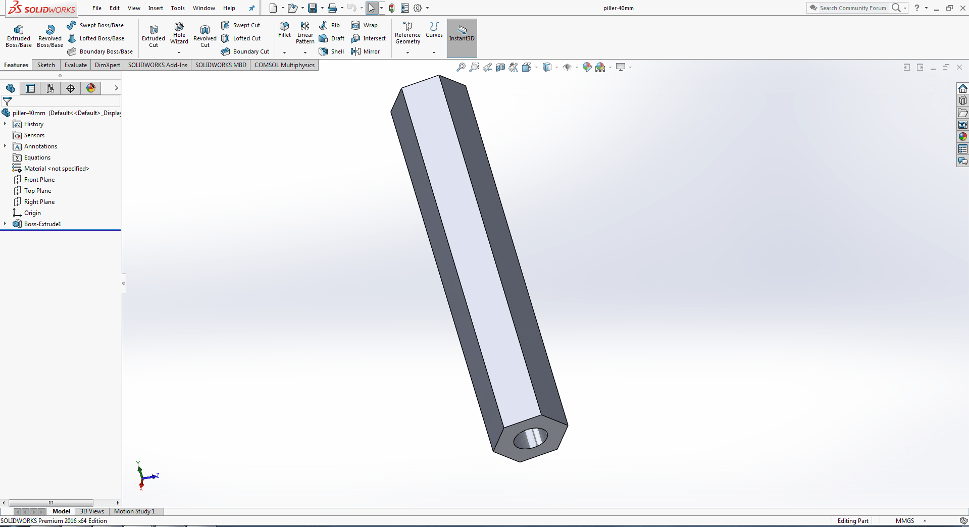
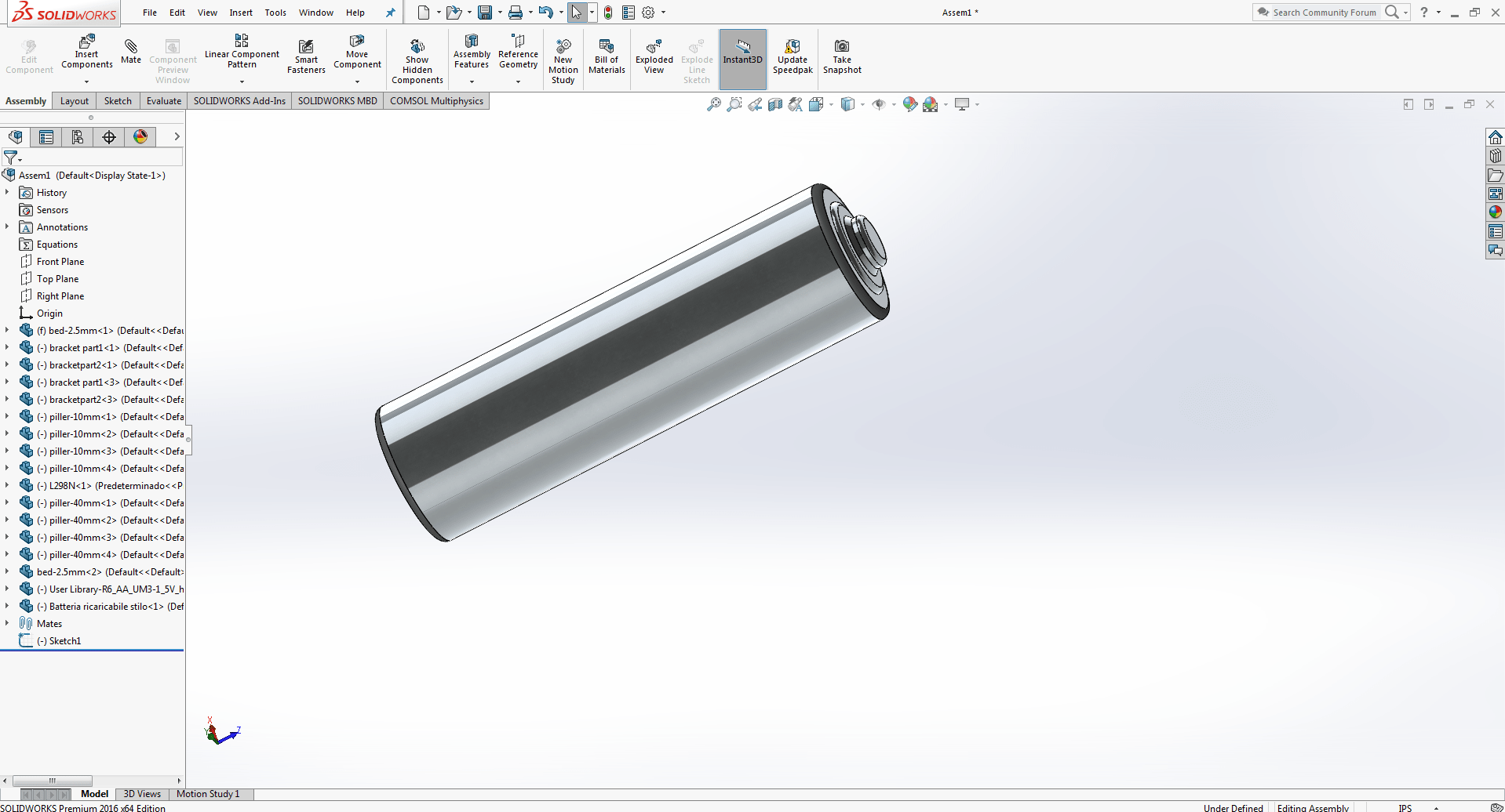
SHAFT
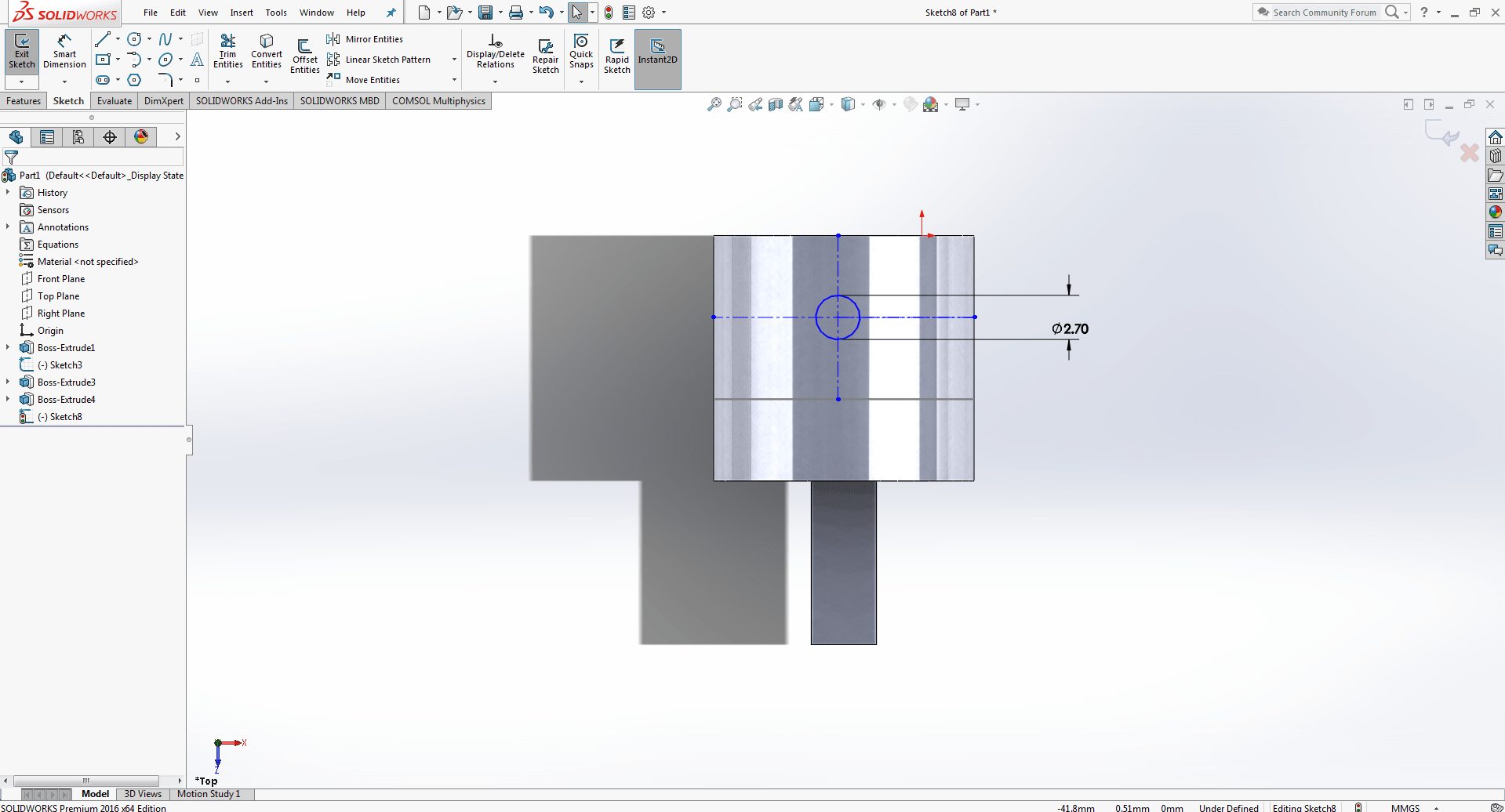
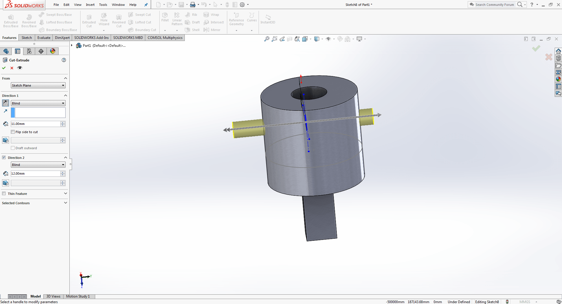
open Solidworks. First, I designed the motor shaft that connects the wheel to the motor.
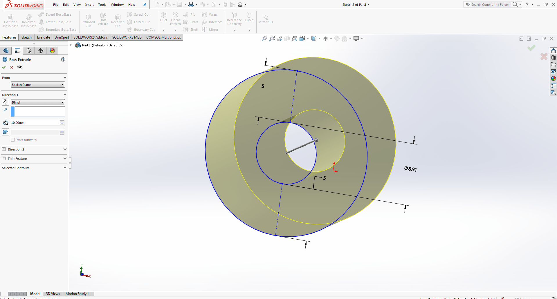
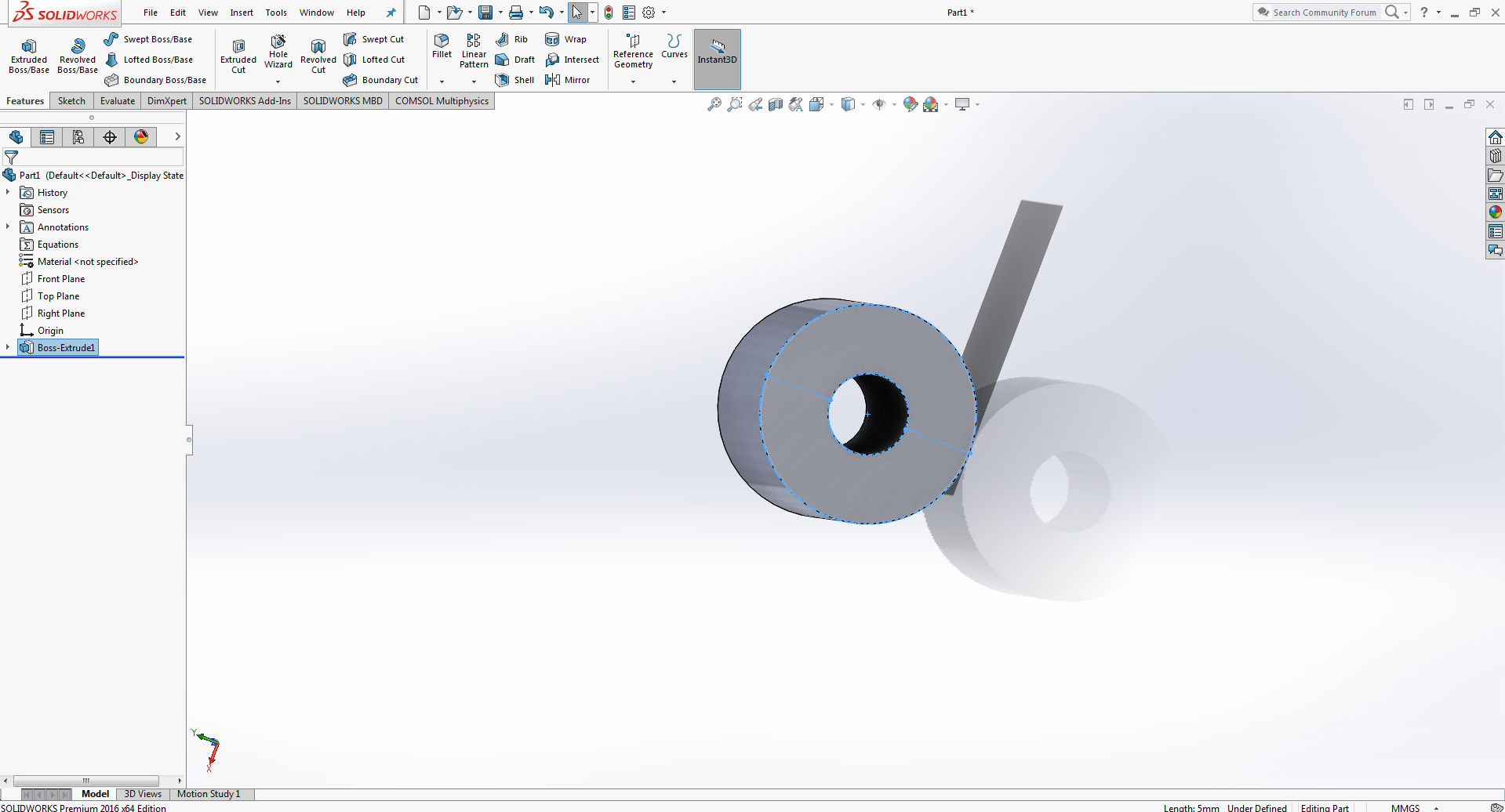

Now draw circle of 2.7mm on the side of the part. Extrude cut the the circle for fixing the shaft to the motor.
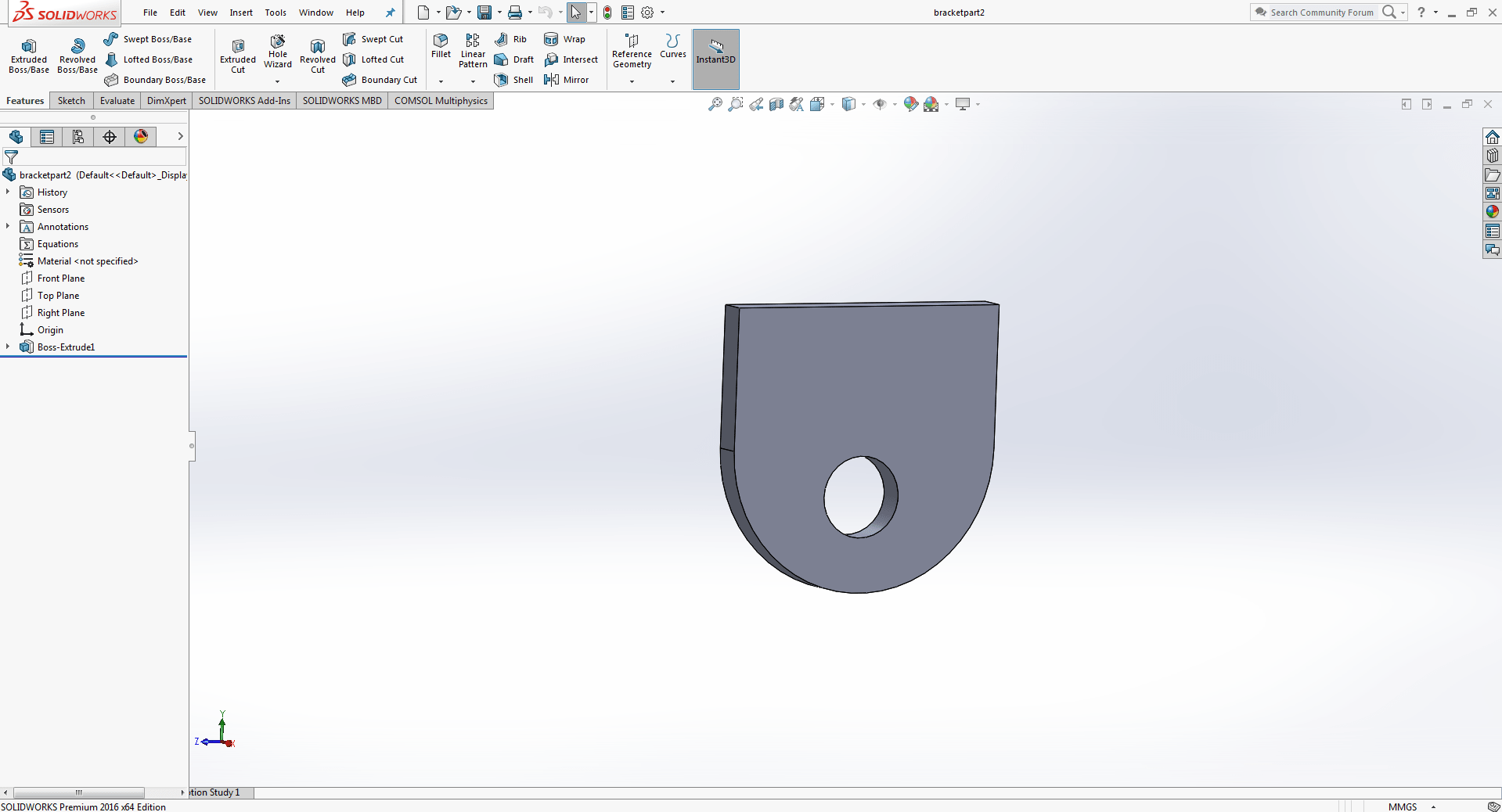
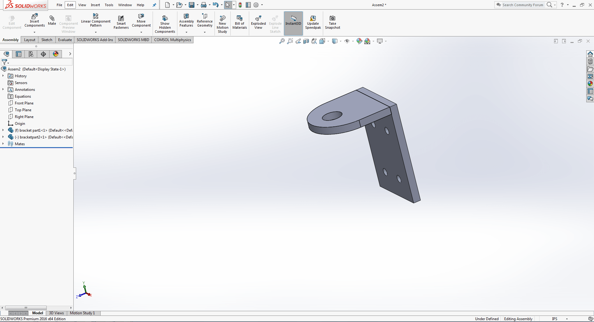
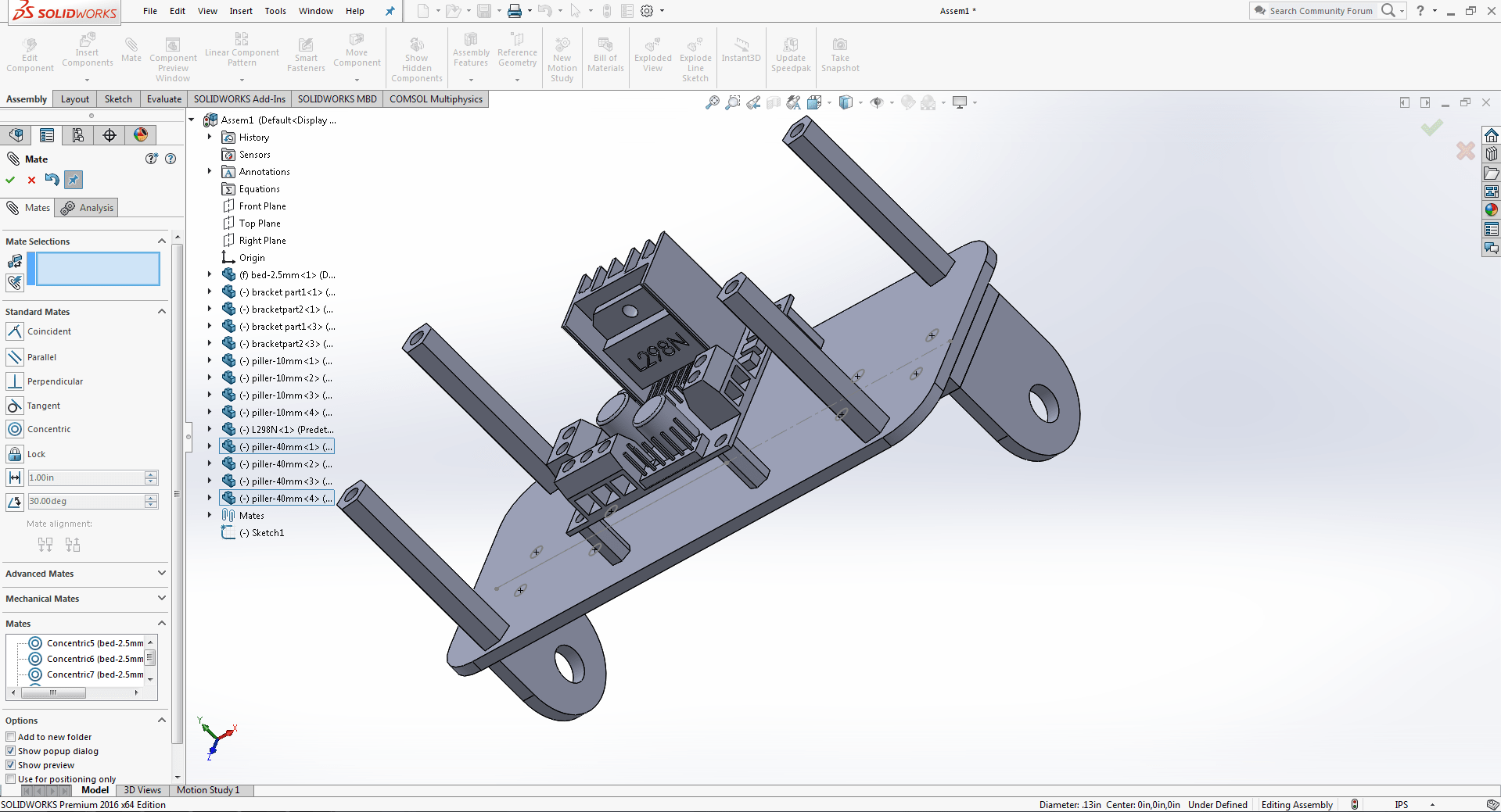
Chassis and support
This is the motor and wheel support that attaches to the base.
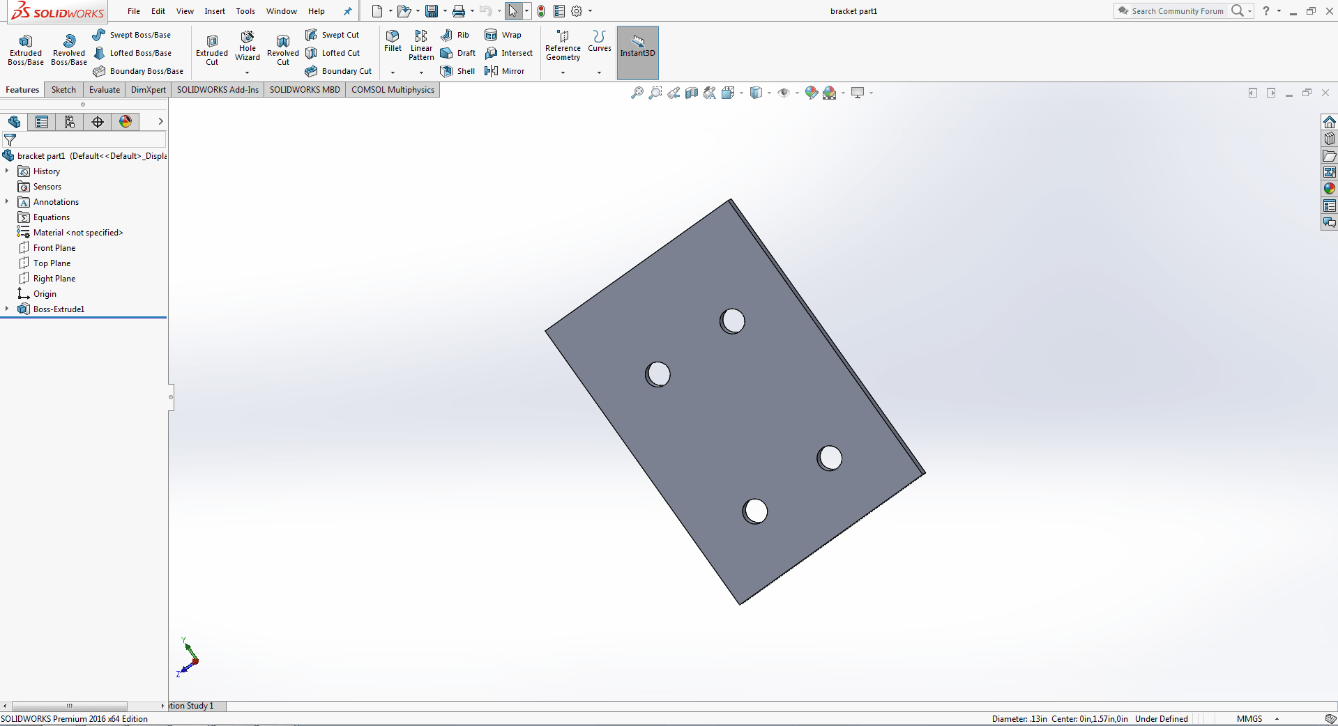
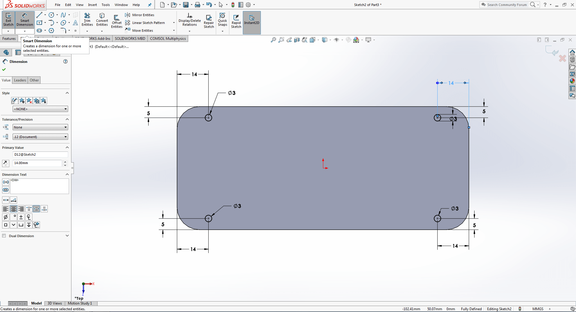
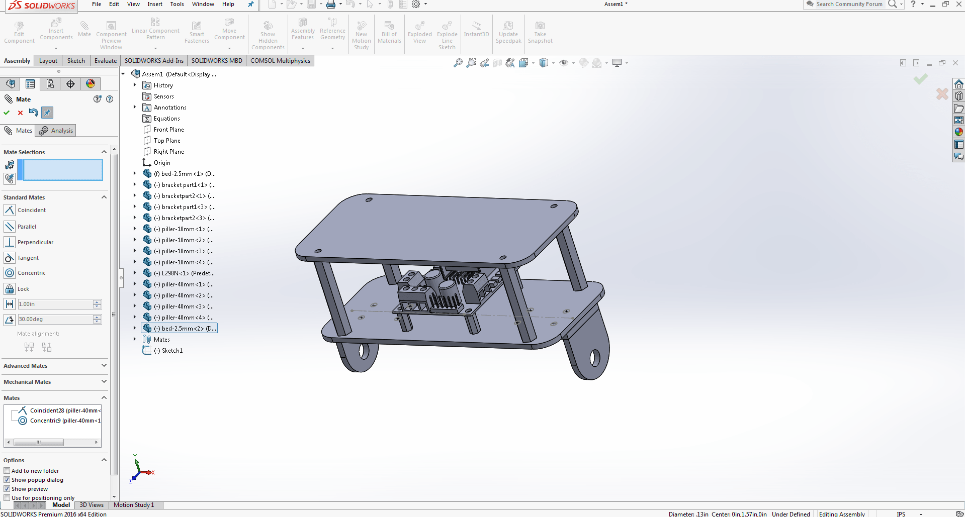
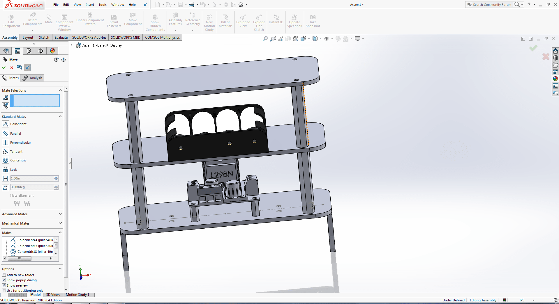
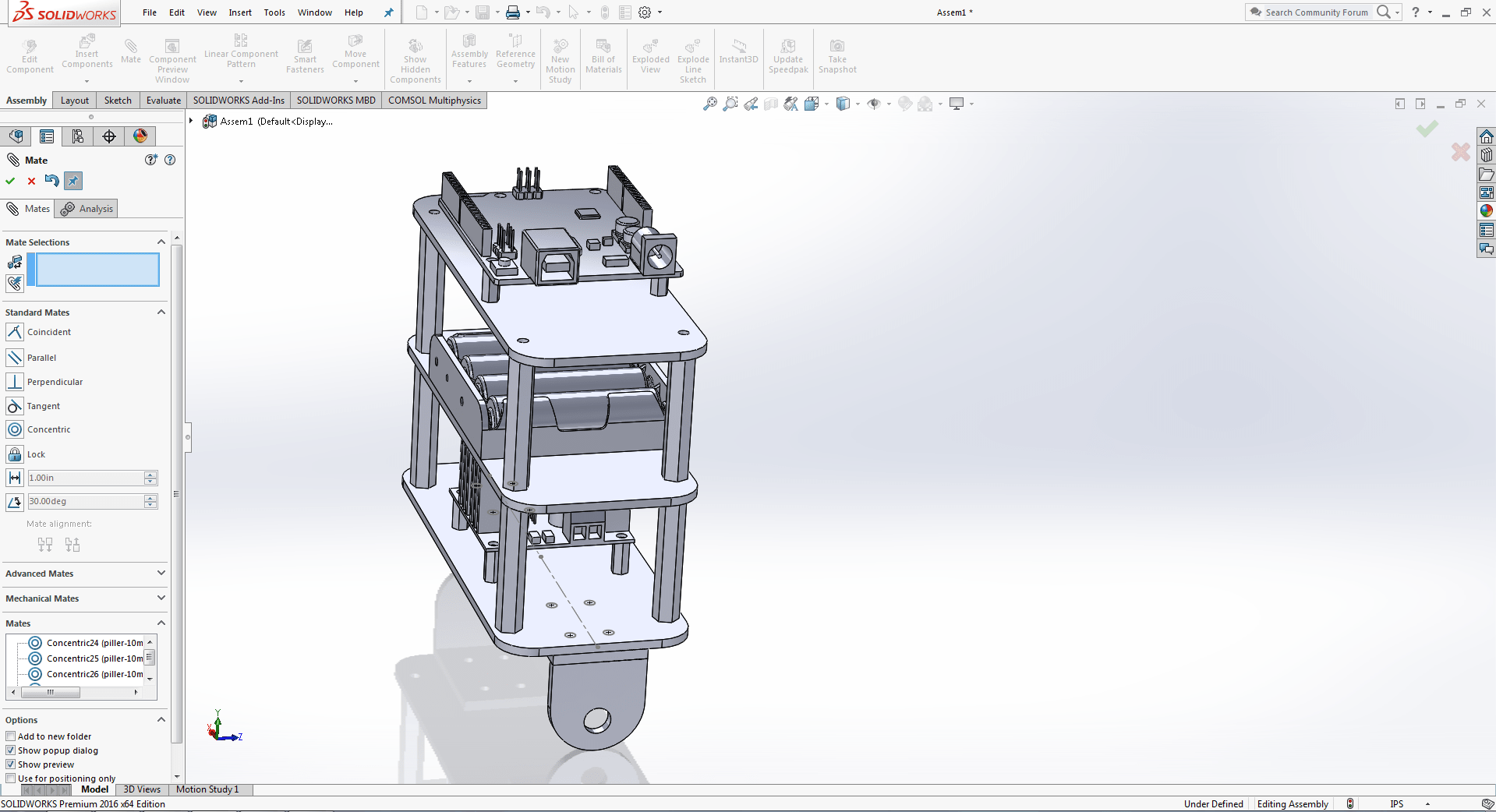
Base
We want to make two floor, where we use to place electronic components on each floor.
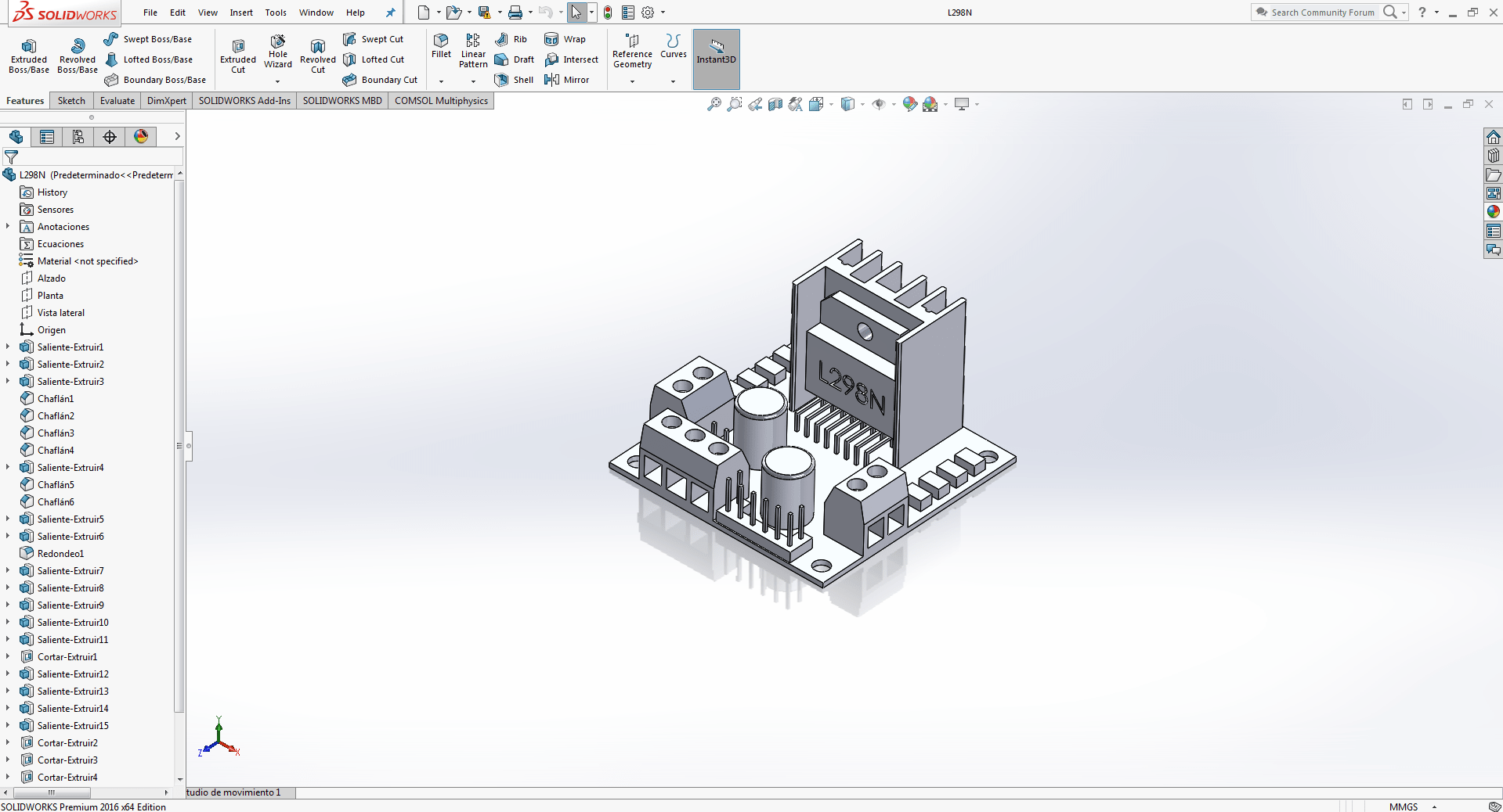
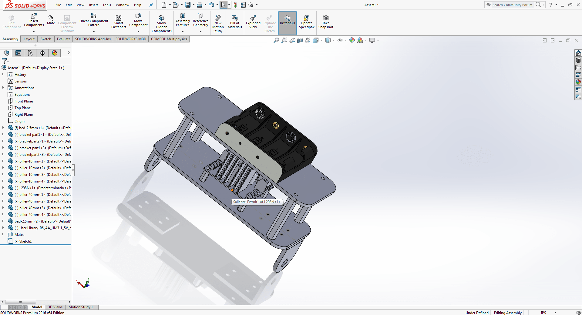
Motor Driver
Motor driver, we are going to put ground floor.
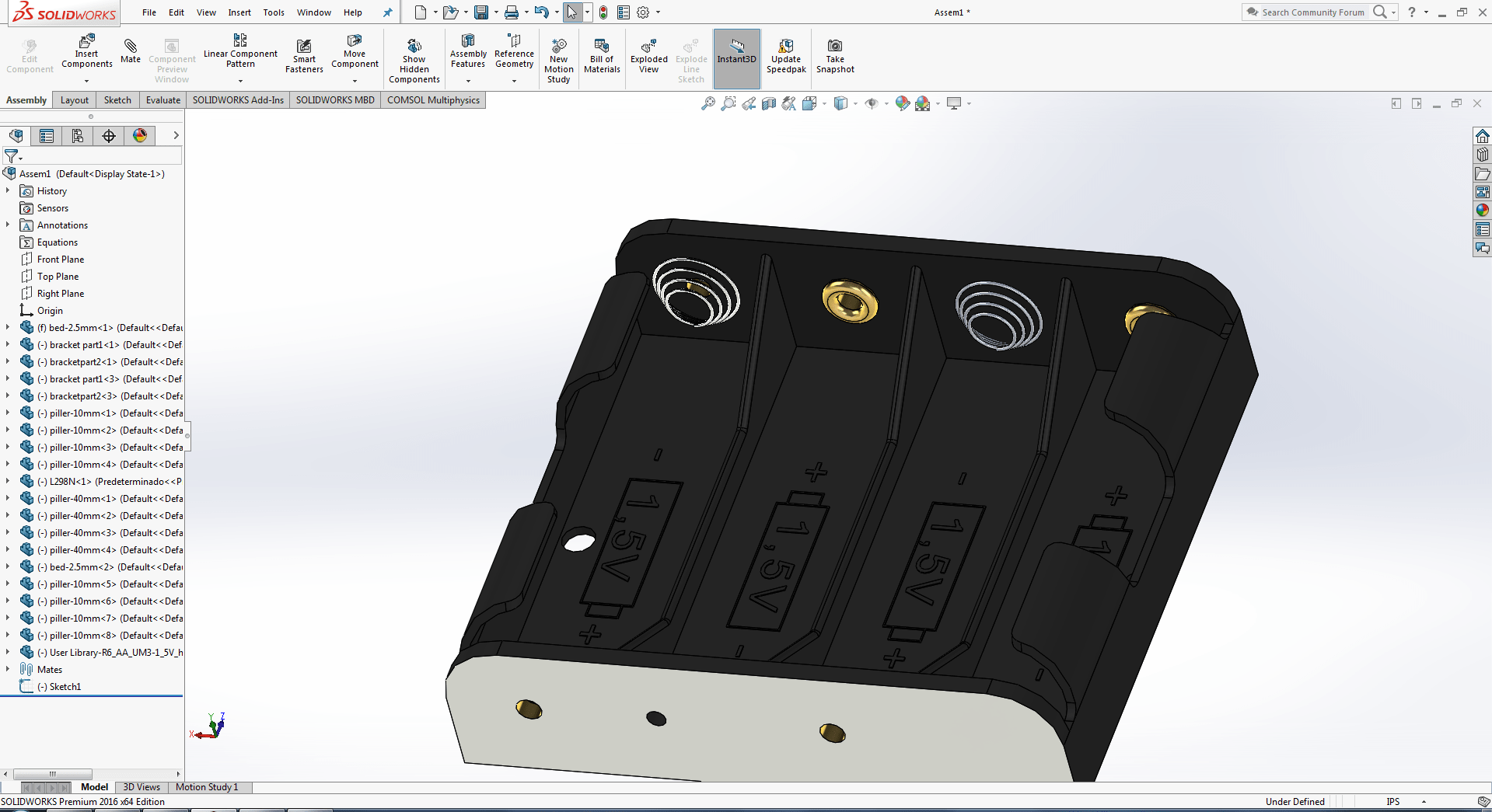
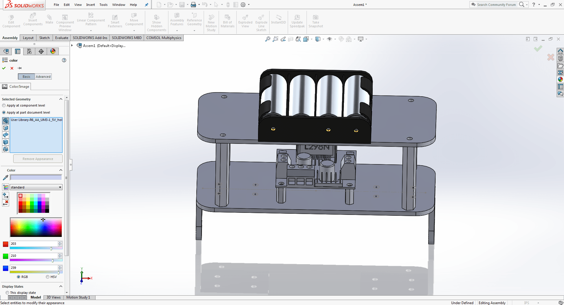
Bettery holder
We decided to instal betteries on the first floor since splitting current on the ground or second storey is challenging.
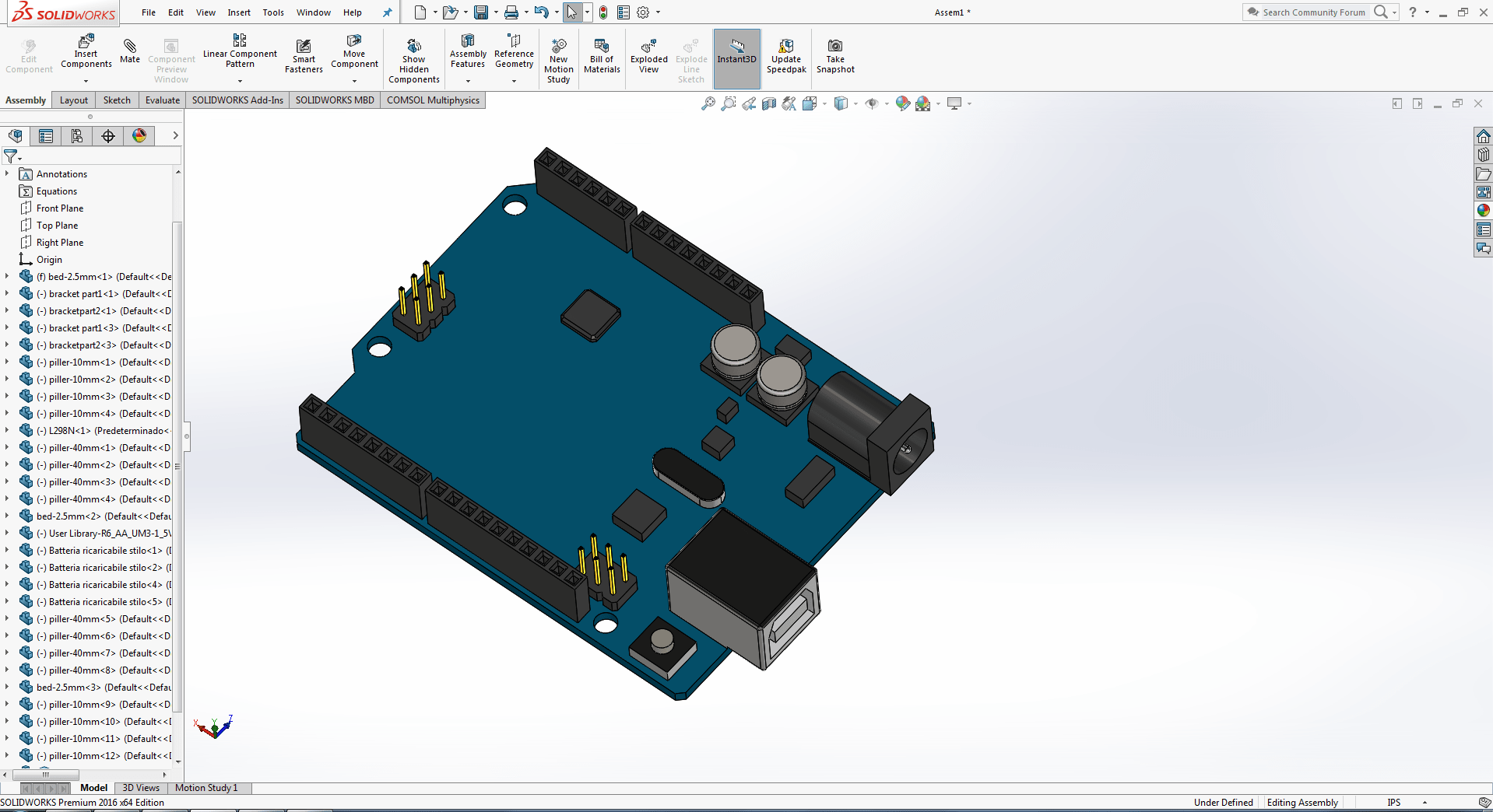
Micro-Controller
We decided to place a microcontroller on the top floor.
Recognised Improvement
We may obtain a satisfactory result by ensuring correct weight distribution in the robot vehicle, since gravity plays a role in balancing the robot. To do so, we must measure all parameters that can cause the vehicle to become unbalanced. Always test your designs before making the actual thing.
"Click here"to download all files of this week