
|

| Sukkur IBA University Merit, Quality, Excellence |
Week - 8
Embedded Programming
Assignment
Group Assignment
In this Group assignement we have study about data Sheet and Architecture of Micro Controller.
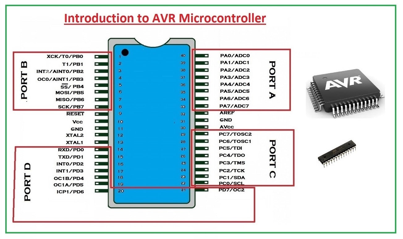
Introduction to AVR Microcontroller
The microcontroller is the advanced version of microprocessors. It contains an on-chip central processing unit (CPU), Read-only memory (ROM), Random access memory (RAM), input/output unit, interrupts controller, etc. Therefore a microcontroller is used for high-speed signal processing operation inside an embedded system. It acts as a major component used in designing an embedded system Click. Where AVR microcontroller is an electronic chip manufactured by Atmel, which has several advantages over other types of the microcontroller. We can understand the microcontroller by comparing it with Personal Computer (PC), which has a motherboard inside it. In that motherboard, a microprocessor (AMD, Intel chips) is used that provides the intelligence, EEPROM, and RAM memories for interfacing to the system like serial ports, display interfaces, and disk drivers. A microcontroller has all or most of these features built into a single chip, therefore it doesn't require a motherboard and any other components, Click. AVR microcontroller comes in a different configuration, some designed using surface mounting and some designed using the whole mounting. It is available with 8-pins to 100-pins, any microcontroller with 64-pin or over is surface mount only.
CPU: The CPU has an 8 bit ALU with a status register, stack pointer, and 32 general-purpose registers. 8 GPR can be used as a 16-bit register; 3 of the double register as address pointer (X, Y, Z). The GPR is part of the SRAM and thus volatile, meaning they lose their content without power, and are not defined when power returns. Control Unit: The RISC command and control unit with program counter can treat most 16-bit commands (instructions) in one clock cycle. We reach near 16 million instructions per second ([MIPS]) Instructionspersecond#Millionsofinstructionspersecond_(MIPS)) with a 16 MHz crystal (about the speed of an INTEL 80386 in 1990). Click. Input/Output: Depending on the controller we get from one to four 8-bit GPIO ports, 8- and 16-bit timer/counter, a real-time clock (RTC), PWM outputs, external interrupts, serial interfaces (EIA232, I²C(TWI), SPI), analog to digital converter (ADC), USB. Memory: Three memory blocks are available. Non-volatile 16-bit Flash program memory, a little non-volatile 8-bit EEPROM, and the volatile 8-bit SRAM. We will look in detail at these memories in this chapter, Click. Programming logic: The controller memory (FLASH, EEPROM, fuse, and lock-bits) can be programmed and cleared over SPI (Serial Peripheral Interface) in-system (ISP).
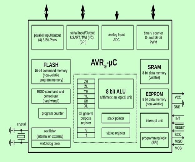
AVR's are available in many different housings and can use voltages from 1.8 V to 5.5 V. Apart from ISP they can be programmed using a bootloader (Arduino) or debugged over JTAG.
PIC Micro Controller
PIC is a Peripheral Interface Microcontroller that was developed in the year 1993 by the General Instruments Microcontrollers. It is controlled by software and programmed in such a way that it performs different tasks and controls a generation line. PIC microcontrollers are used in different new applications such as smartphones, audio accessories, and advanced medical devices. There are many PICs available in the market ranging from PIC16F84 to PIC16C84. These types of PICs are affordable flash PICs. Microchip has recently introduced flash chips with different types, such as 16F628, 16F877, and 18F452.
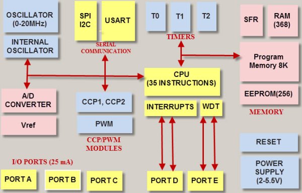
PIC Microcontrollers Architecture
The PIC microcontroller is based on RISC architecture. Its memory architecture follows the Harvard pattern of separate memories for program and data, with separate buses.
Individual Assignment
Read a microcontroller data sheet Program your board to do something, with as many different programming languages and programming environments as possible
ATtiny 44A Datasheet
I started reading the "Micro-controller Datasheet" to get a general idea about the Micro-controller and its structure. I used attiny44 for my hello-world board. The attiny 44A is an IC with 14 pins. 1. The datasheet gives us pin configuration which helps us while soldering as well as programming. We can find out our mistakes while programming the board by using this pin configuration.
VCC - This pin where voltage supplied.
GND - Ground pin
Port B(PB3...PB0)is a 4-bit bi-directional I/O port with internal pull-up resistors.
RESET - The reset pin can also be used as a (weak) I/O pin.
Port A (PA7..PA0) is a 8-bit bi-directional I/O port with internal pull-up resistors. Port A has alternate functions as analog inputs for the ADC, analog comparator, timer/counter, SPI.
ATtiny24A/44A are low-power CMOS 8-bit micro-controllers based on the AVR enhanced RISC architecture.
Block Diagram
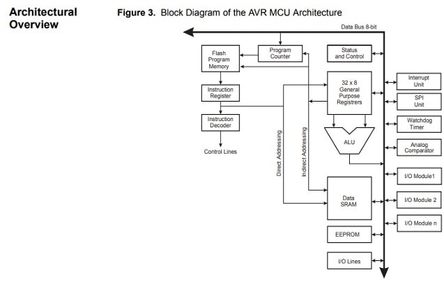
The AVR uses a Harvard architecture with separate memories and buses for program and data.
Arduino IDE
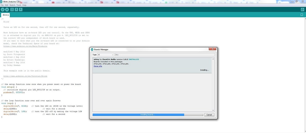
For the Programing I used the Ardiuno ID, Go to the Tools and Select the Board, Board Manager and install the moderboard for attiny44.
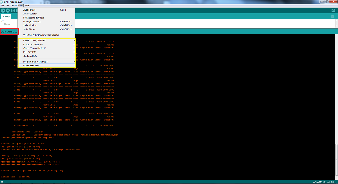
After update the boot load the Programmer. Go to the Tools and Select the Board attiny44.
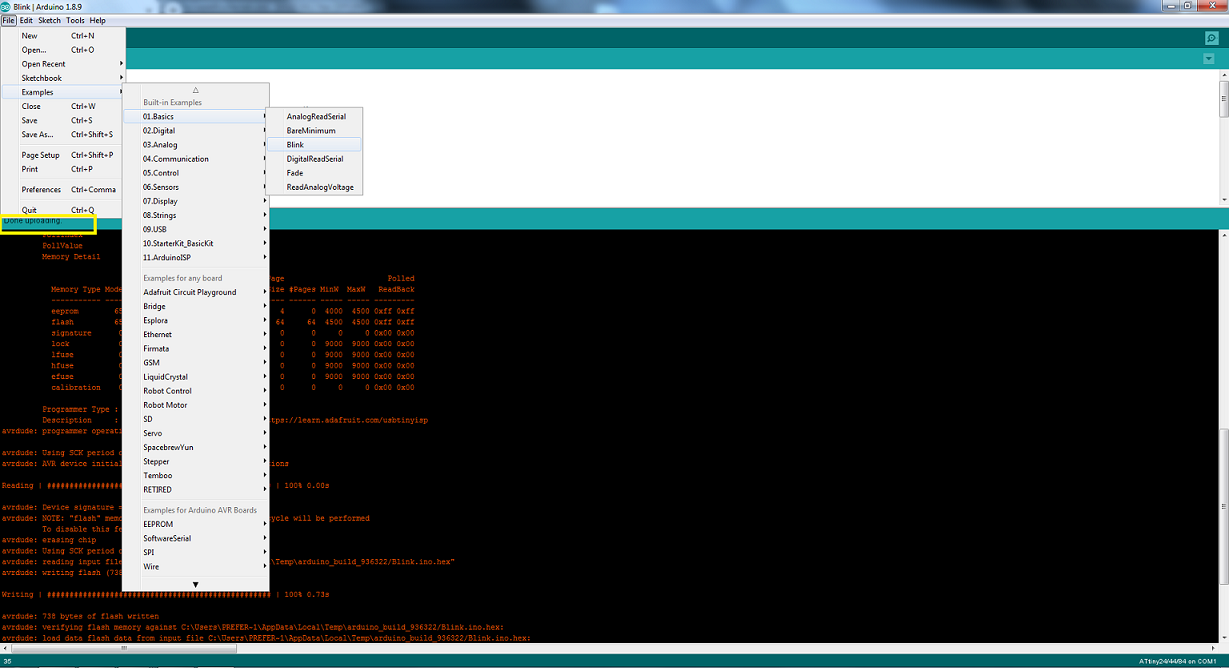
Now this result Show that my board is Working, First I have to test the led Blink code to check that it's working.
I uploaded push button program when i pressed the button led Glow.
ATMEL STUDIO 7 : CODE
I am not using the same code (PushButton) that I had previously created, i have changed code but instead of using Arduino IDE to upload it to my PCB, I used Atmel Studio 7.
#include

#include


int main()

{

    DDRB |= (1 << PB0);

    while(1){

        PORTB |= (1 << PB0);

        _delay_ms(100);

        PORTB &= ~(1 << PB0);

        _delay_ms(100);

    }
}
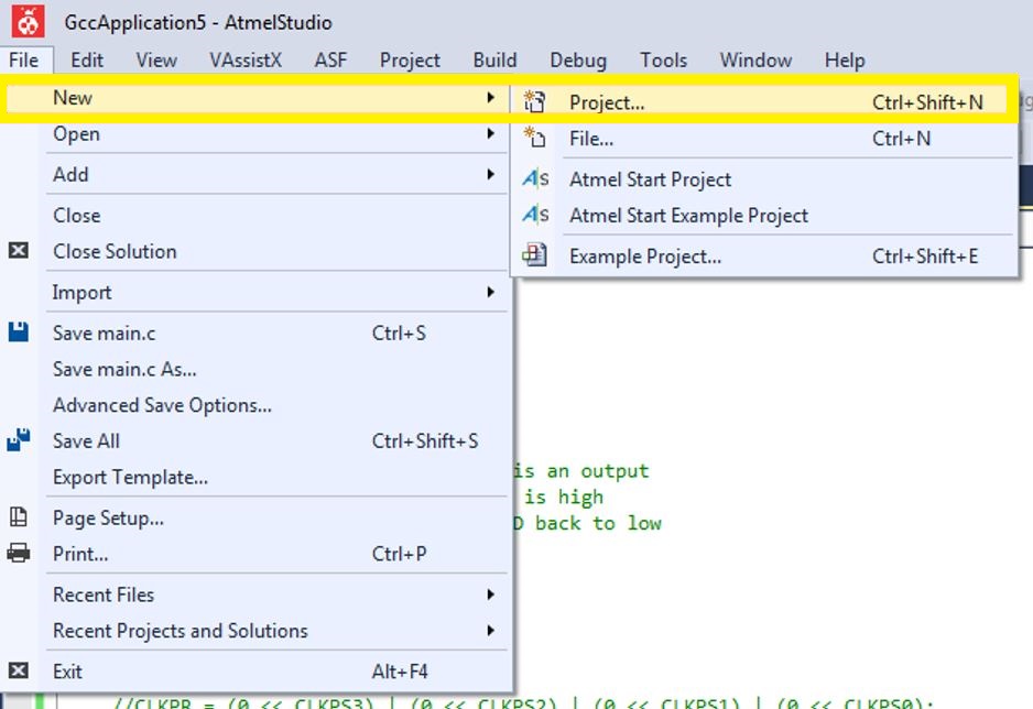
Programming with Atmel Studio
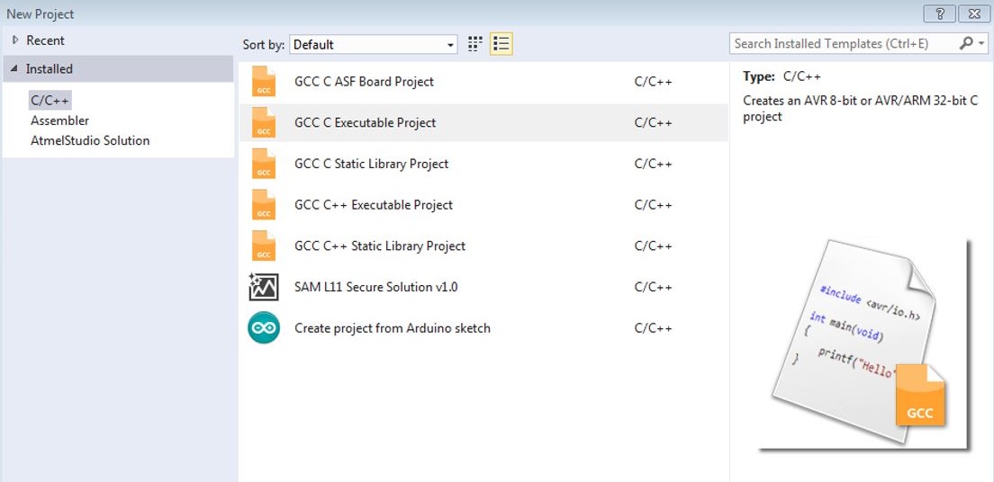
- Start a new project goto File-->New-->Project
- In the window select C/C++ as language and select the second one from the selected list
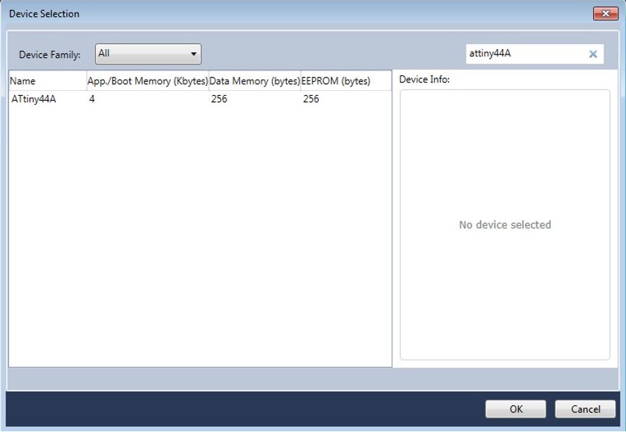
- Select Attiny as the device family and select Attiny44A from it and press OK.
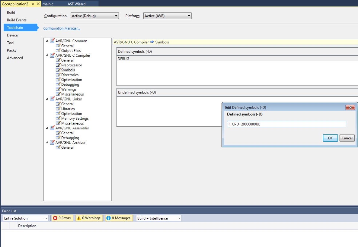
- Goto Debug-->GccApplication4 Properties, Define the External/Internal Clock i.e in my case External Clock : 20000000UL
Create an External Tool from Tools top menu.
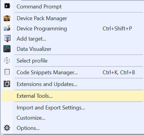
Add a new external tool and set as the following:
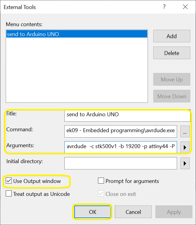
Title:Give title name. Command:Navegate to your arduino installation avrdude.exe file.
Arguments:copy and paste the following:
avrdude -c stk500v1 -b 19200 -p attiny44 -P COM8 -e -u -U flash:w:\Users\Mansoor\AppData\Local\Temp\arduino_build_893397/ButtonCode.ino.hex:i
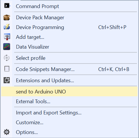
You could change (attiny44) to the avr chip that you are using and (COM8) to the USB port that you are connecting to. While the part after (w:) can be copied from the arduino IDE after uploading the code. You can see the new tool now from the Tools menu.
"Click here"to download all files of this week