
|

| Sukkur IBA University Merit, Quality, Excellence |
Final Project
Presentation Slide
Final Project Video
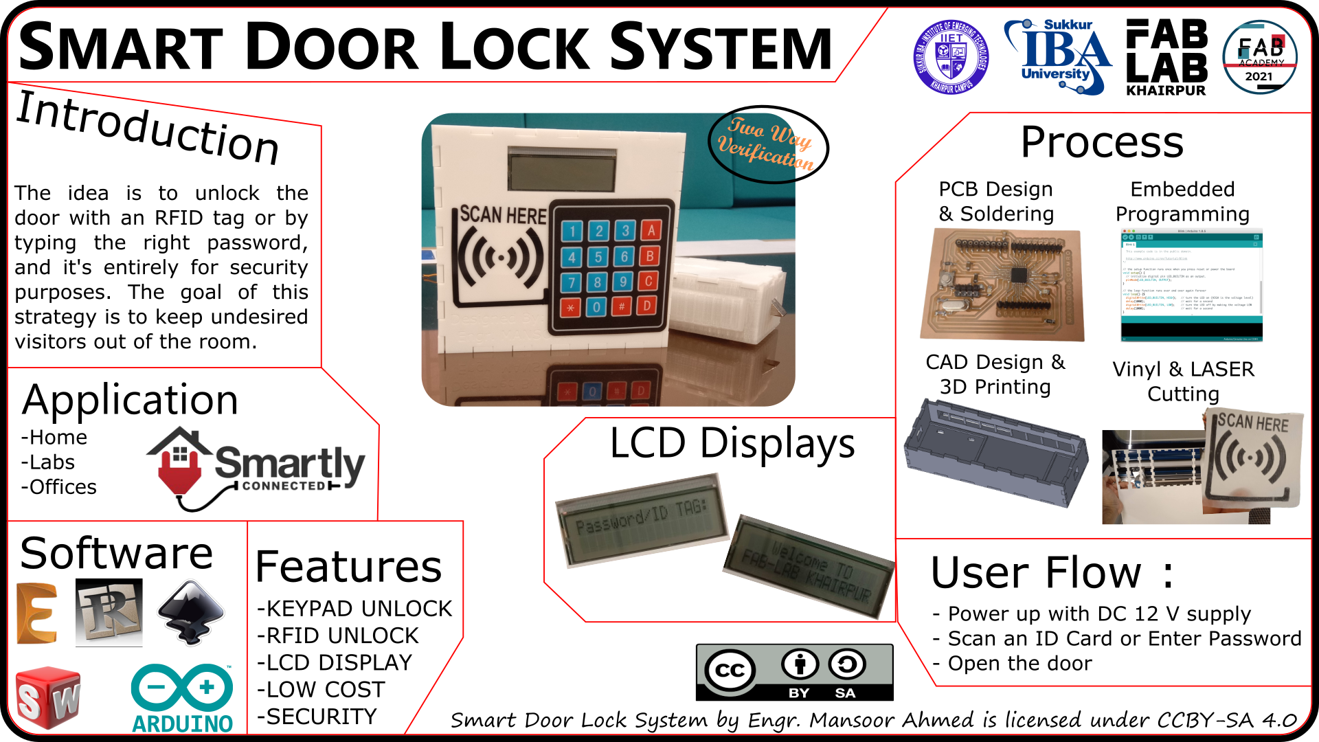
Presentation
I've decided to work on a Smart door lock system for my final project as part of the Fab Academy programme. The concept is to open the door using an RFID tag or by entering the correct password, and is thus purely for security reasons.
Motivation
Sometimes, we need to lock a room in our house or business (maybe a secret laboratory) so that no one may enter without our permission and our valuable accessories and valuables are protected from theft or loss. There are many different types of security systems available today, but they all rely on fingerprints, face id, RFID readers, passwords, pins, patterns, and other biometrics for identification. Off all the solutions the low-cost one is to use a password or RFID-based system. So, in this project, I have built an micro-controller RFID, Keypad Door Lock which can be mounted to any of your existing doors to secure them with a digital system.
Project History
SKETCH
The first drawing of the Smart door lock system I imagined at the start of the Fab Academy programme is shown below:
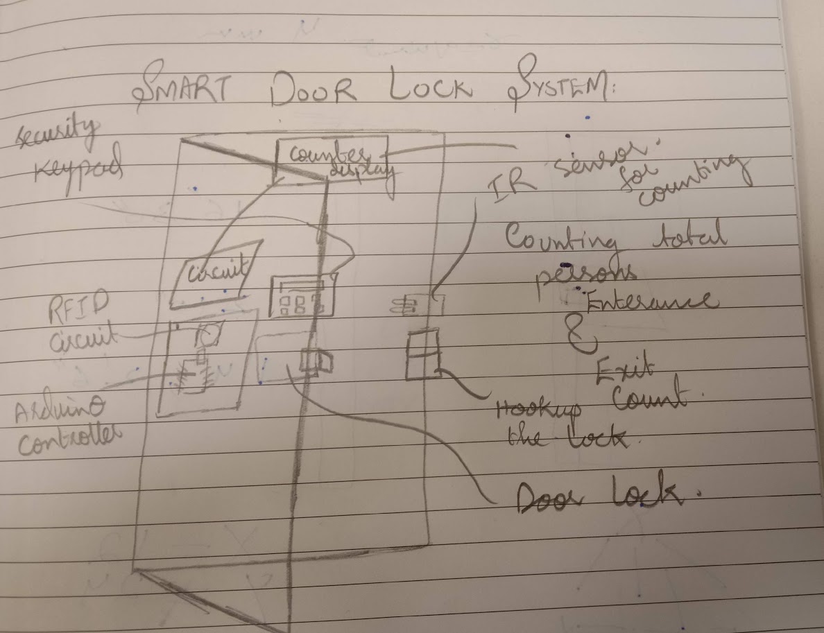
Basic Idea of my project
To create a smart door lock that can be opened using a radiofrequency identity card (RFID) and a keypad lock so that those who do not have an RFID card may open the door using a passcode. The objective for this proposal is to keep undesired persons out of the room.
Block diagram

CAD Designing
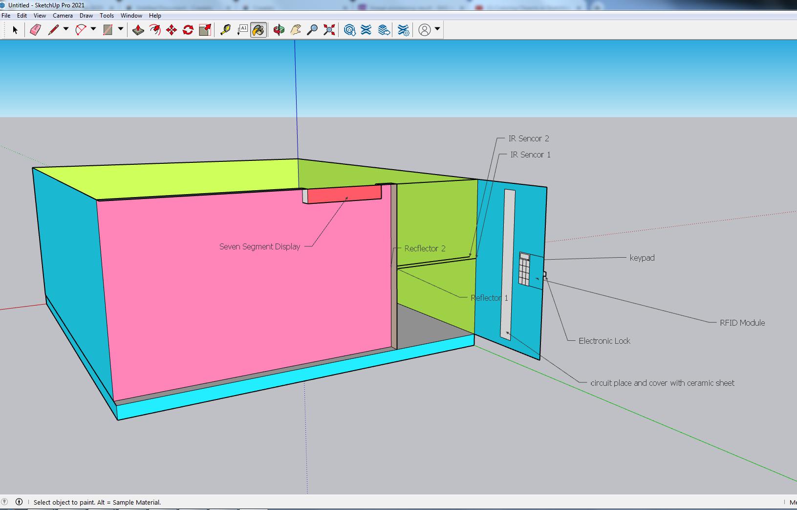
3D Designing on sketchup
An example of a smart door lock installed in a room is shown below:
Design For 3d Printing
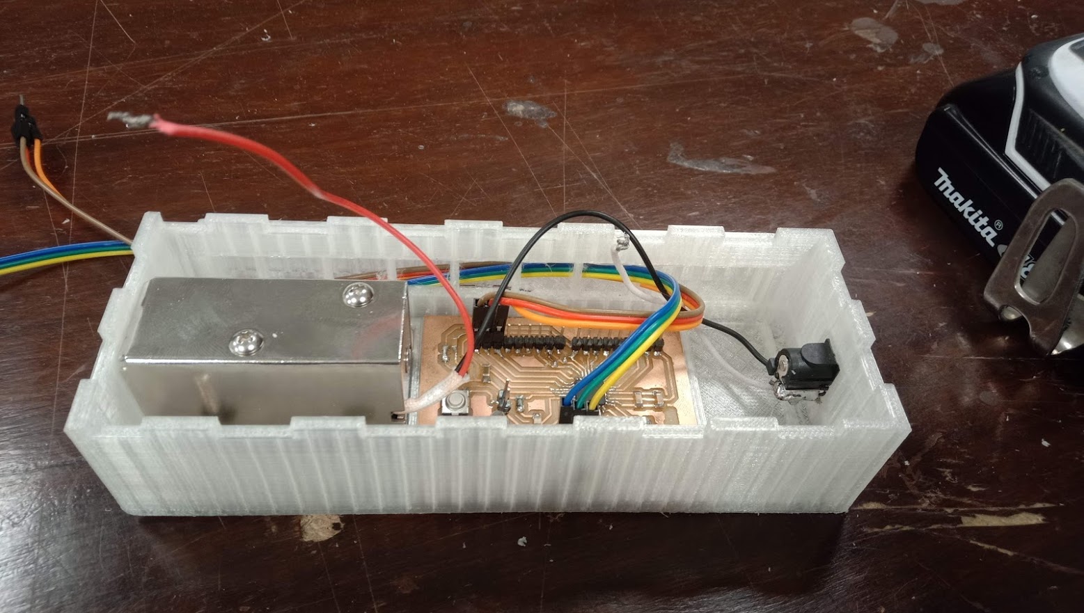
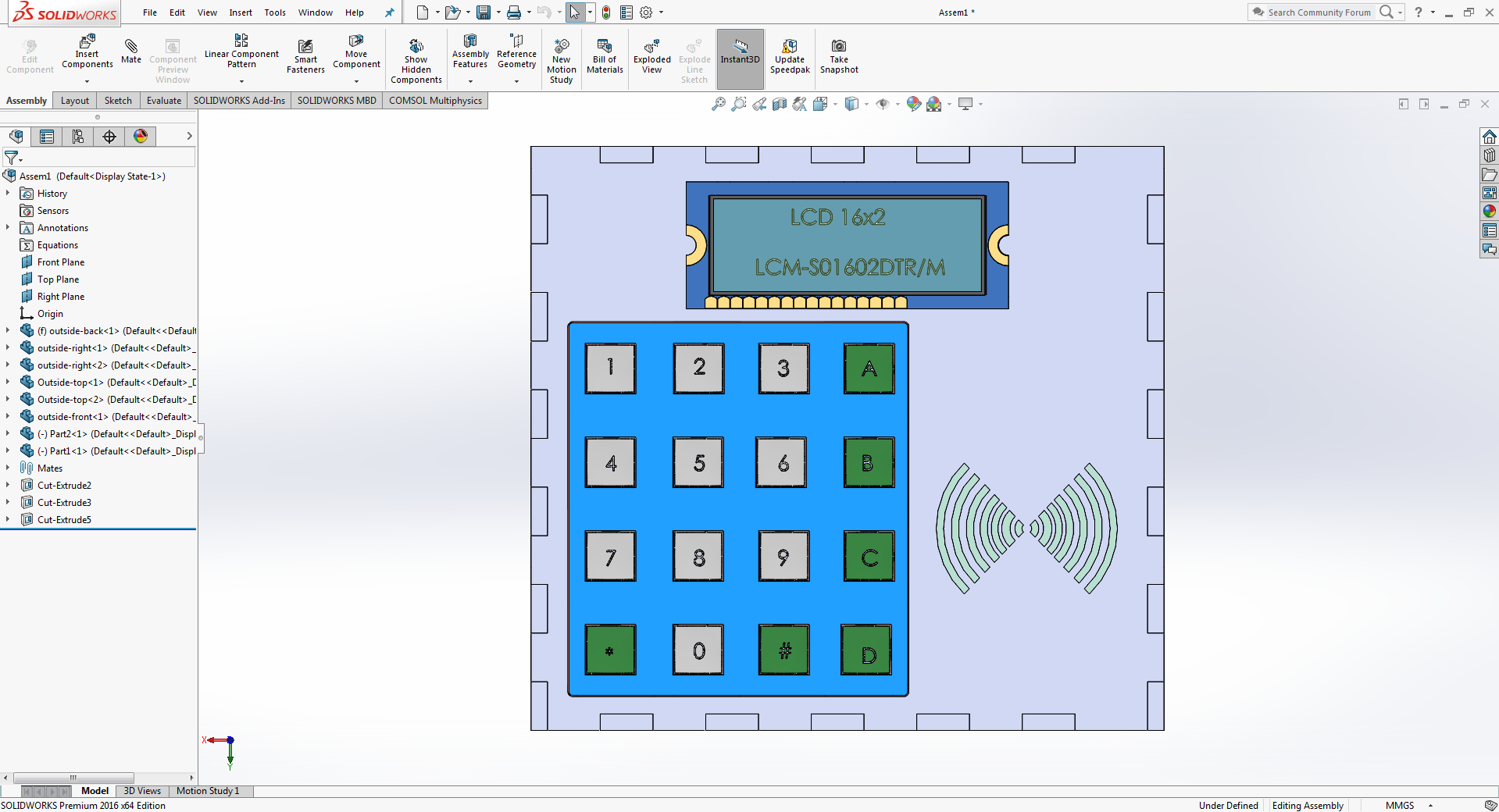
I designed the box on solid work to instal the electronic equipments such lock, circuit, and relay module all in one box.
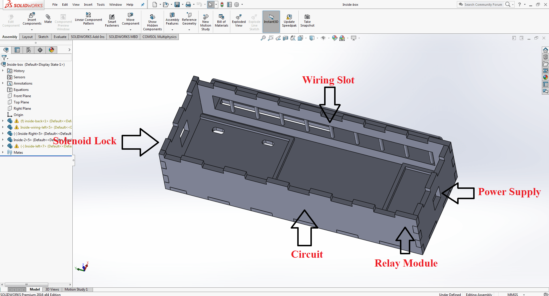
By utilising dimention, I made three sections in the box to insert the lock, circuit, and relay.
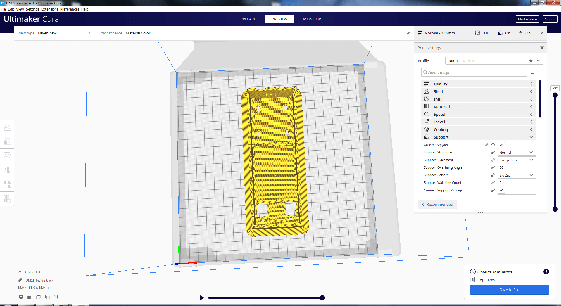
Creating a gcode file for a three-dimensional printer
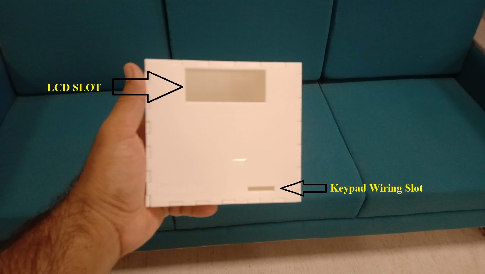
Three slots are exactly fitted: one for circuits, two for relay module, and three for solenoid lock, and I've cut a hole for the dc supply as seen below:
This is the third dimension of my design.
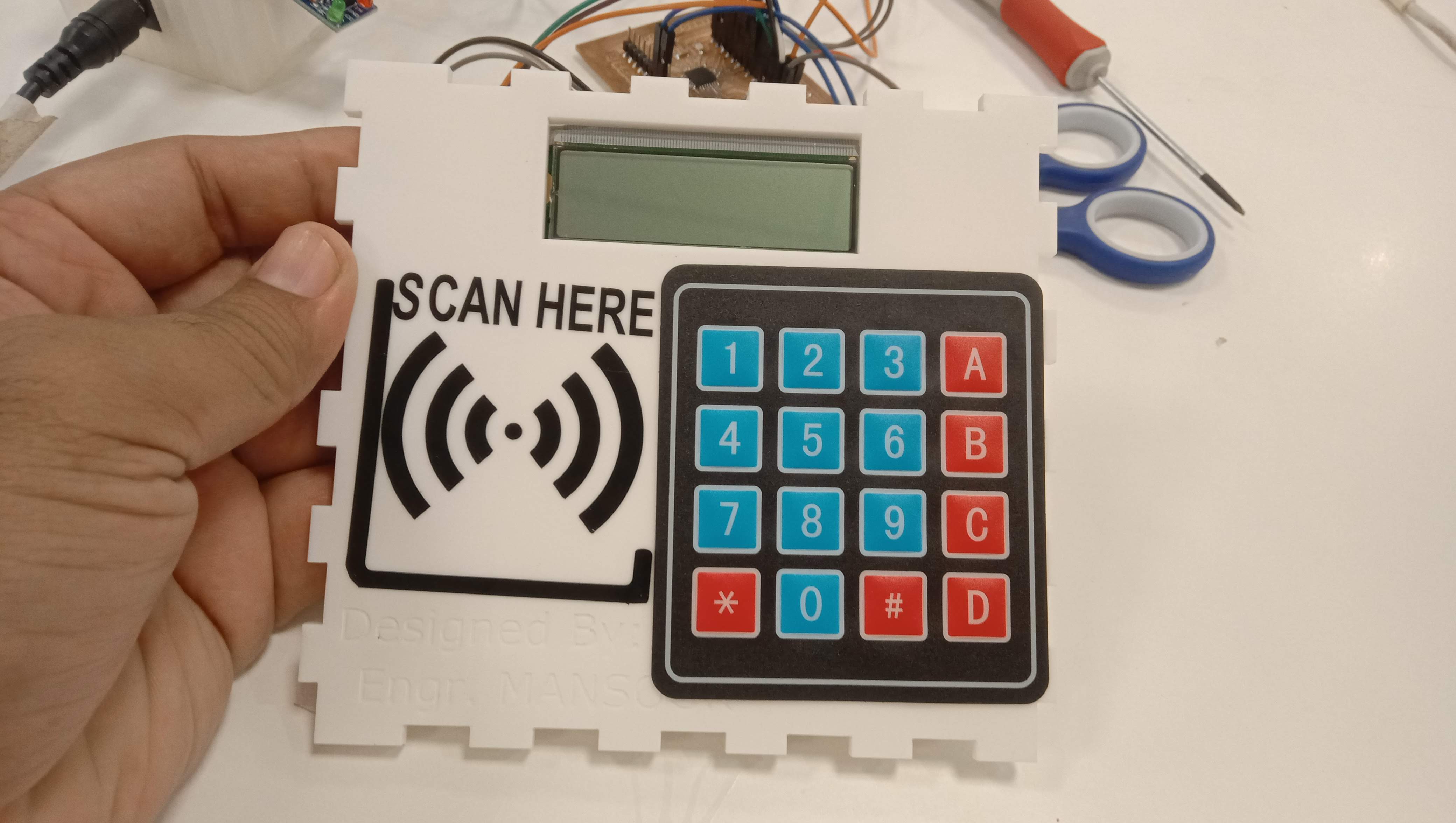
Keypad Design
This section is where I design the keypad that will be shown in my final product.
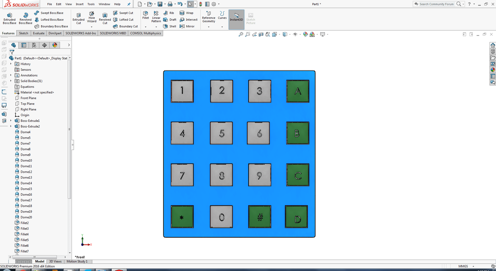
4x4 keypad i am going to use in my project
LCD Design
I'm planning to show the user massage on 2 X 16 LCD .
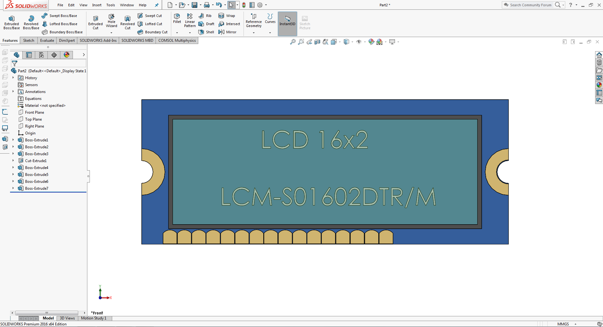
I took dimensions with a vernier calipher.
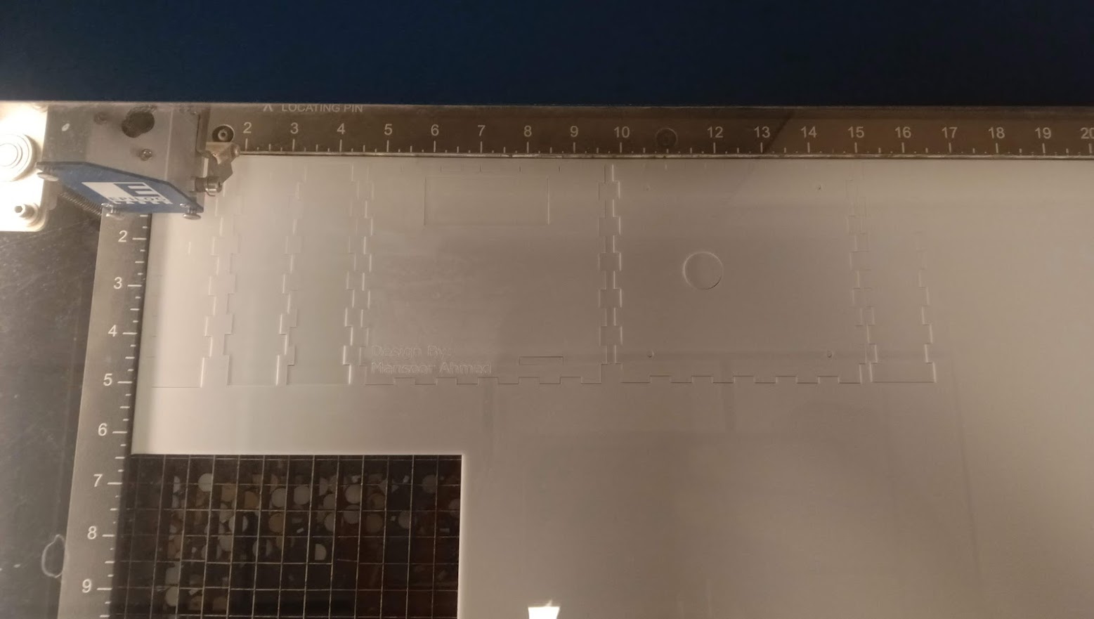
Design For Laser Cutting
Assembling all parts to gather before cutting because if there are any size errors, they may be corrected before cutting, resulting in a faultless outcome.
After I completed putting all of the pieces together, I moved on to two-dimensional cutting.
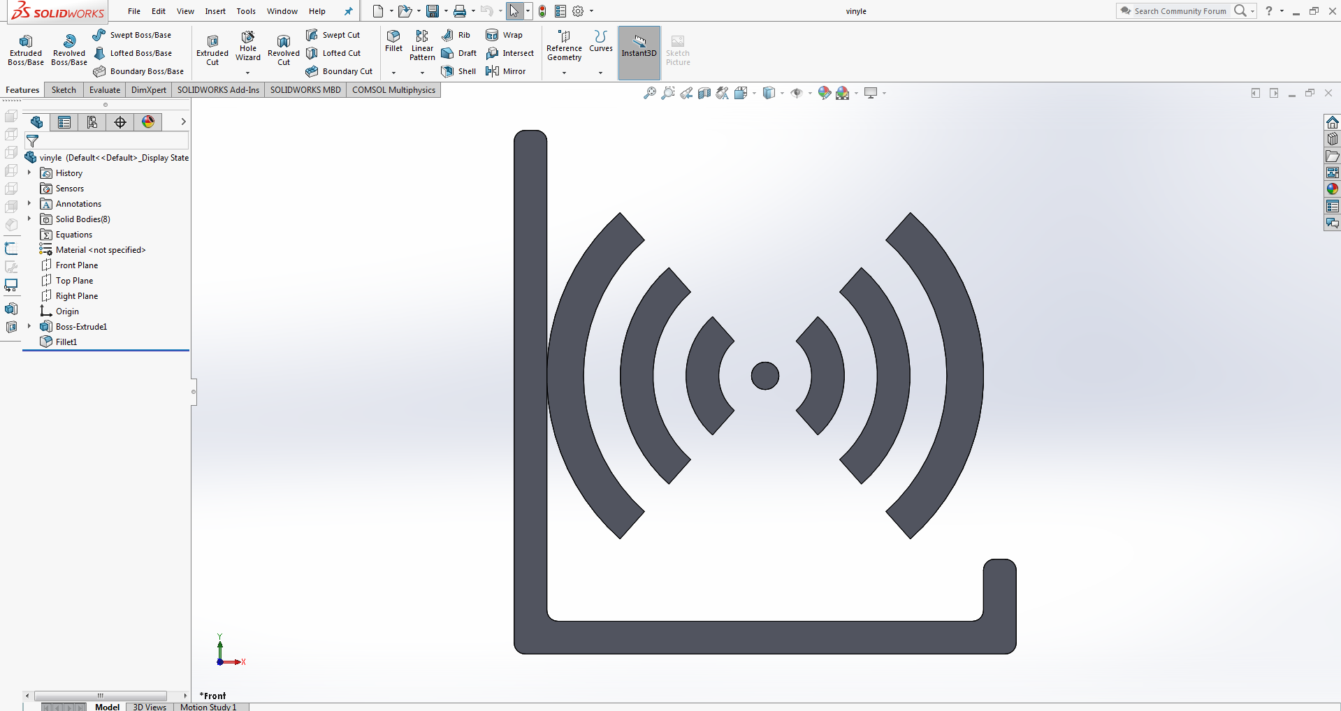
Design For Vinyle Cutting
I designed a logo to assist users in determining where RFID tags should be placed.
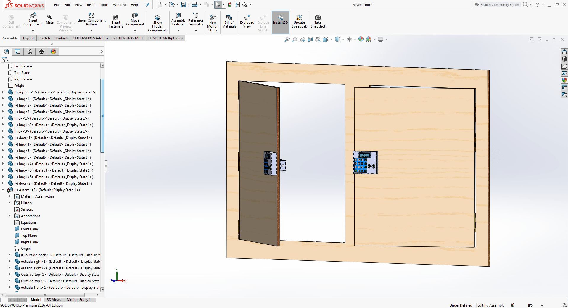
Cabinet Design
I'm planning to include a system within the cabinet since I don't want to remove the lock from the door before testing the system. Removing the lock from the door is difficult since there is a risk of extra holes appearing where the lock was attached.
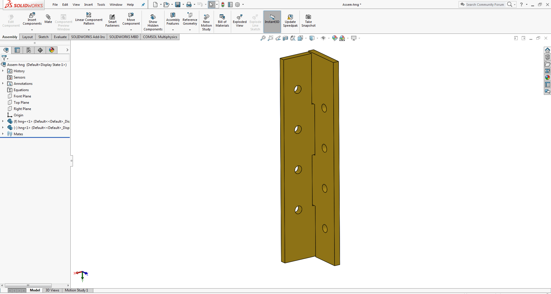
I created hinges to mat the door and support it.
This is the final CAD design for my project for putting all electronic equipment. As you can see, I've designed two boxes for the inside of the door and the outside of the door is matted to this door.
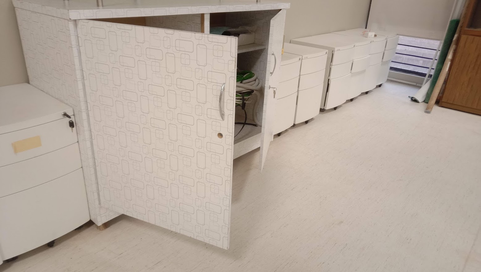
This is the cabinet where I'll be installing my smart door lock system, and all measurements are taken from it.
Electronic Devices
Micro-Controller
I chose the ATMega 328P microcontroller it has enough pins to meet my needs and, more significantly, it is compatible with the Arduino Uno Board, which I use as a reference board for testing and development. As there were quite a few uncertainties in getting started with the AtMega328P I decided to follow Daniele Ingrassia’s Satchakit which is an improvement on the earlier Fabkit mainly in that it: We’ve got inputs, and those would be electronic devices that gather information.
This is my primary board, which I will use in my final project.
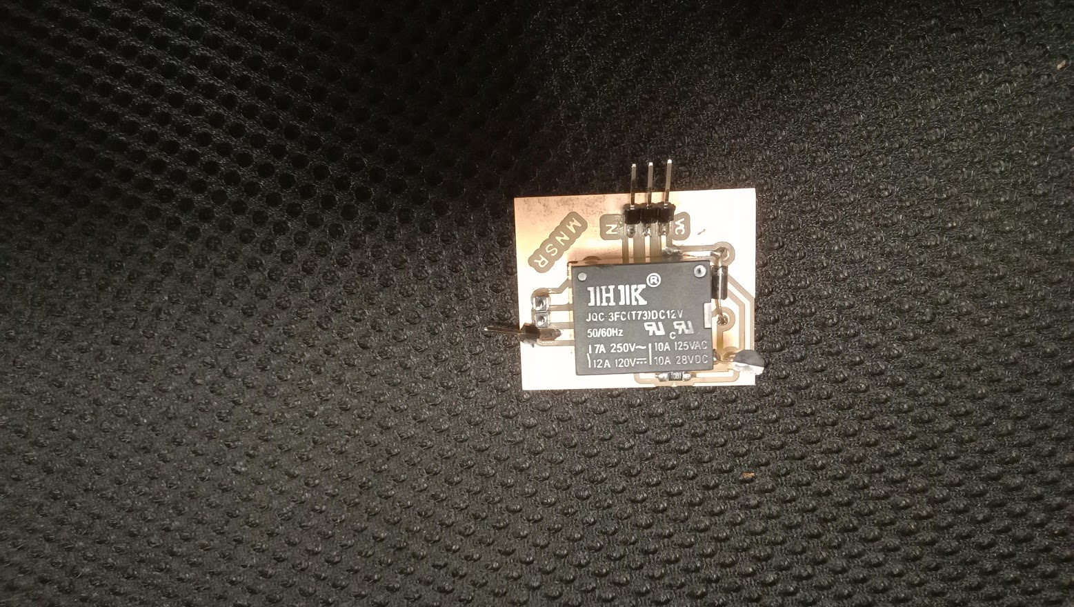
Relay Module
A relay is an electrically operated switch that can be turned on or off, letting the current go through or not, and can be controlled with low voltages, like the 5V provided by the Arduino pins.In my final project, I utilised this One Channel Relay Module to operate a 12v solenoid lock.
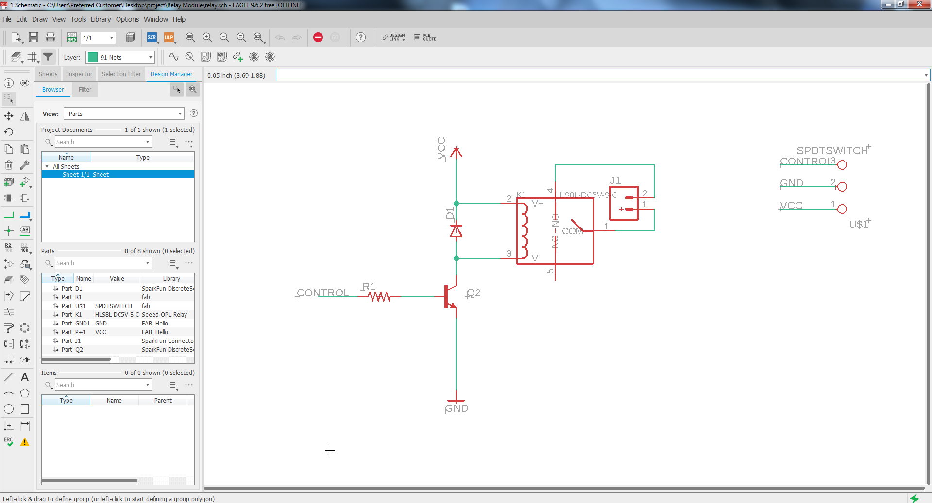
To control the open and close of the lock, I need to incorporate a relay. A relay allows to manage big voltages with a microcontroller that works with a low voltage. In my case, the lock that I am planning to used works between 9 to 12V.
Voltage Regulator
A voltage regulator is used to regulate voltage levels. When a steady, reliable voltage is needed, then the voltage regulator is the preferred device. It generates a fixed output voltage that remains constant for any changes in an input voltage or load conditions.
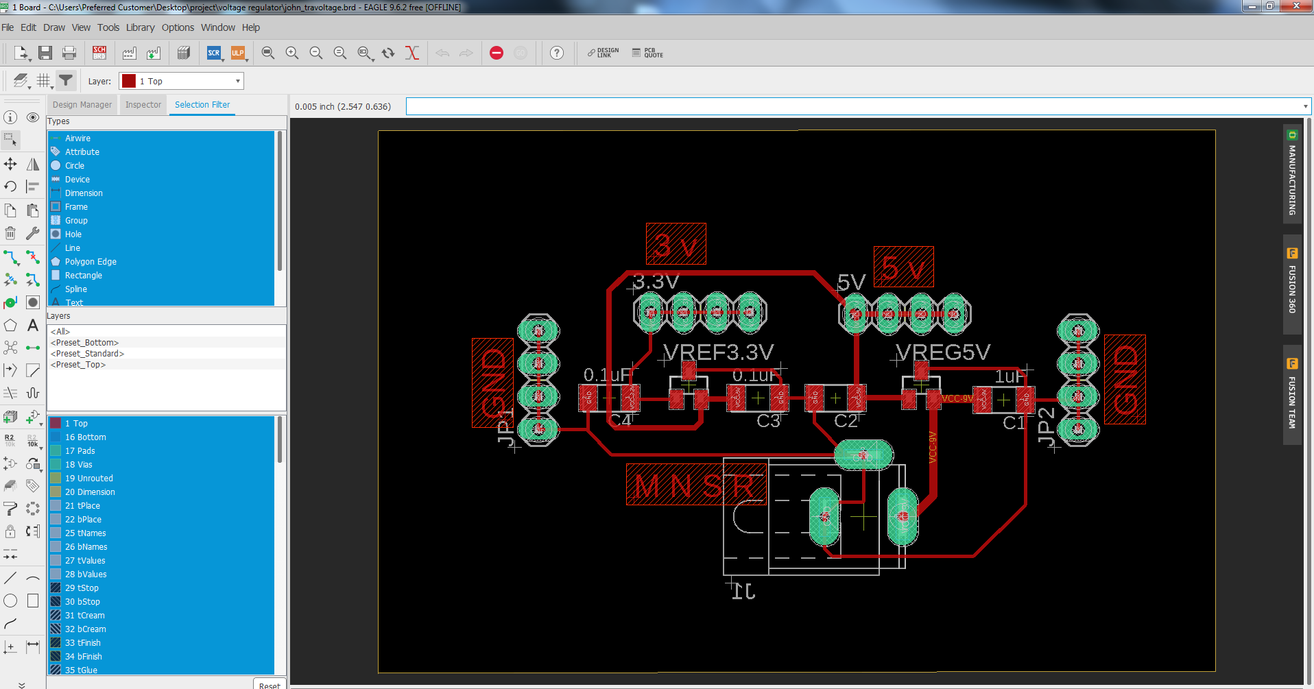
Here are two output voltages 3.3 voltages for RFID and 5 volt for board
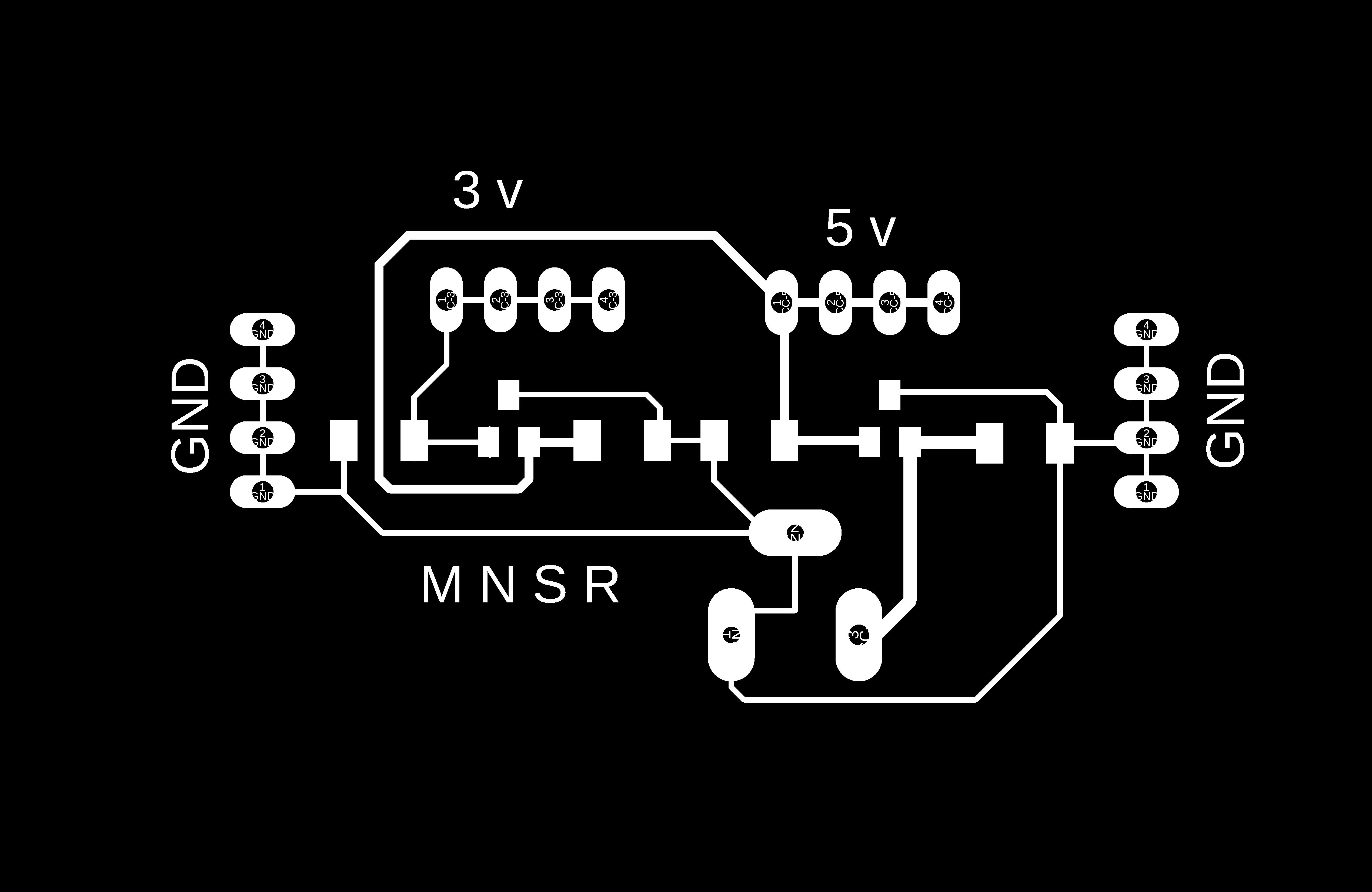
This is PNG which i have milled
During milling the trace, the circuit fly off the bed so I have stopped the machine immediately. The problem was due to that, there was not enough tape under the board to keep it stable. One of the traces was removed, so I have solved the issue by soldering on it.
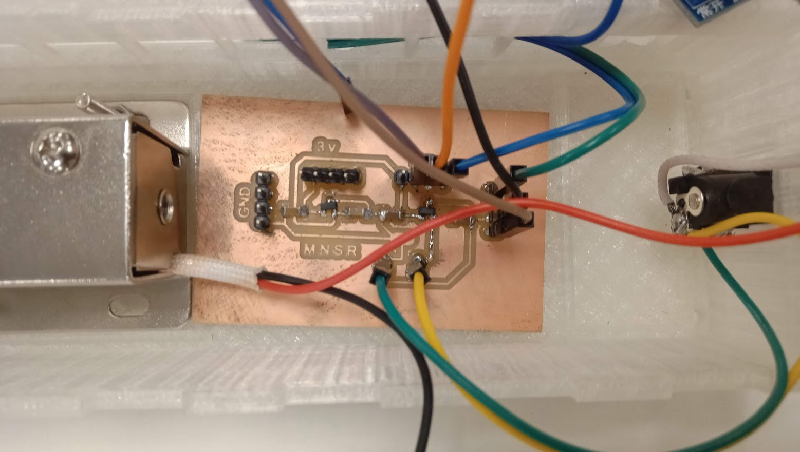
I'm using 9 volts as an input and taking 3.3 volts and 5 volts as a output.
Electronic testing
Access control - RFID
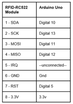
In this part, I'll go over the stages I went through to create an access control system using RFID modules.RFID (Radio Frequency IDentification) system consists of two main components : - a transponder usually in the form of a card or tag. - a transceiver also known as interrogator/reader. As is usual, I began by testing a preliminary version of my access control using the Arduino environment. As a first test, I opted to use the SPI protocol to communicate data between the RFID module and the Arduino (Serial Peripheral Interface).
Connections
Because solenoid locks are unavailable in our lab, I am testing with a servo motor before switching to a solenoid lock.
Solenoid lock mechanism
In this part, I'll go over the experiments I ran to control my solenoid lock mechanisms by using bluetooth module. The second test I ran was to use a microcontroller board to drive a 12V solenoid.
Access control - keypad
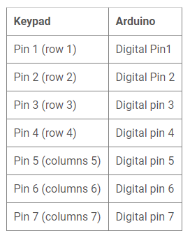
A 16 x 2 LCD is used to display the message to the user; 16 x 2 refers to the number of columns and rows. A 4 × 4 matrix keypad is used. We require a keypad to enter passwords. It has 16 keys (soft switch), four in each row (R1, R2, R3, R4) and four in each column (C1, C2, C3, C4). When a key is hit, it connects the corresponding rows and columns. The table below illustrates how to connect Arduino to a keypad.
The user has three chances to enter the proper password; else, the system will hang for one minute. The hanging time may be adjusted to meet the needs of the situation.
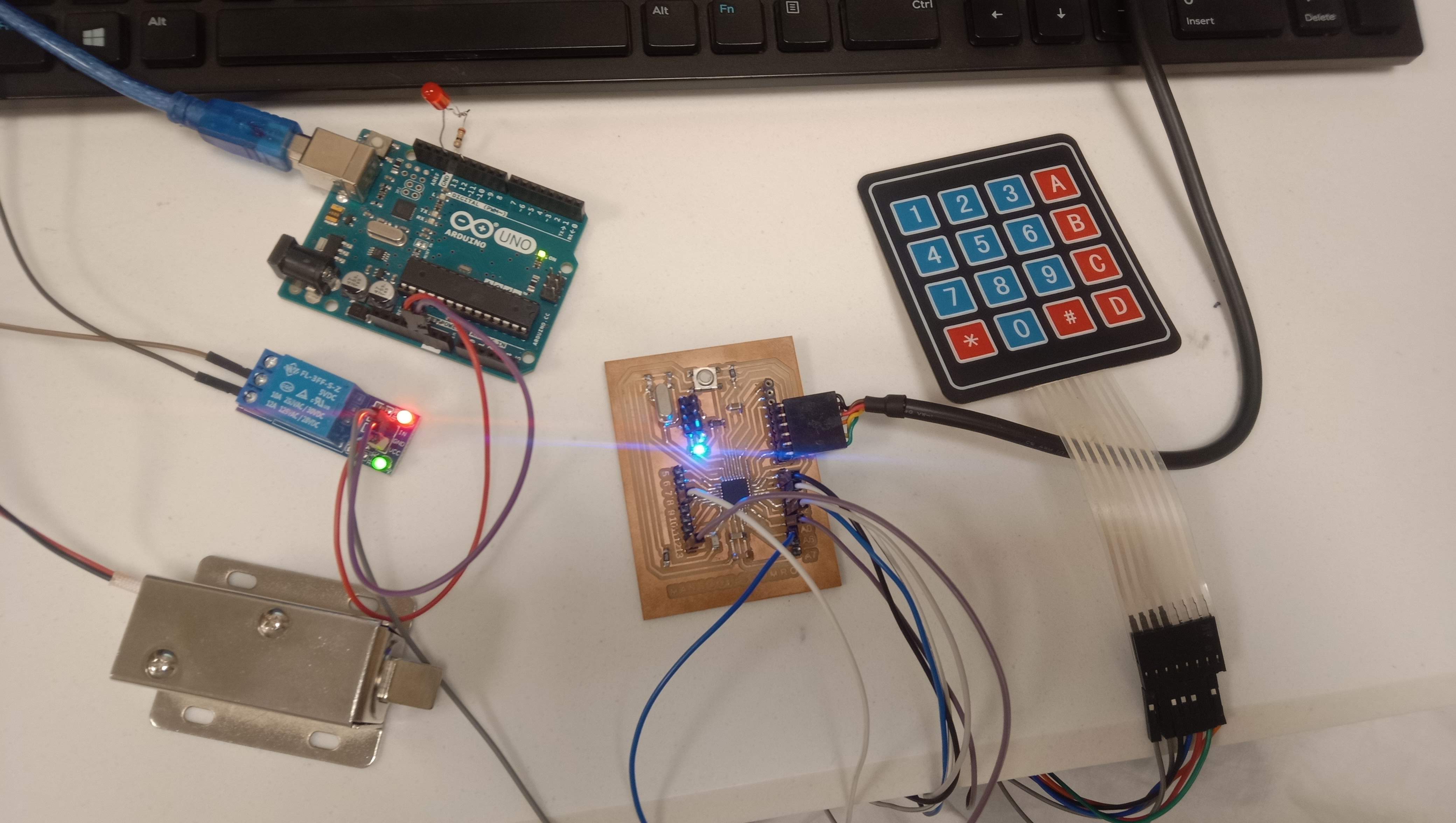
Final Project test
My smart door lock system has three basic components: an outer piece with a keypad, LCD and RFID, an inner piece with power supply, circuitry and the bolt that secures your door. Connecting them all is the challenging part. It is recommended that when using a smart lock for the first time, you test it before installing it, therefore I am doing so. as shown in the video below:
Source Code
I integrated and tweaked the codes I used throughout the testing.
#include "Wire.h"
#include "Keypad.h"
#include "LiquidCrystal.h"
#include "LiquidCrystal_I2C.h"
#include "SPI.h"
#include "MFRC522.h"
#define SS_PIN 10
#define RST_PIN 9
MFRC522 mfrc522(SS_PIN, RST_PIN); // Create MFRC522 instance.
const byte ROWS = 4; //four rows
const byte COLS = 3; //three columns
char keys[ROWS][COLS] = {
{'1','2','3'},
{'4','5','6'},
{'7','8','9'},
{'*','0','#'}
};
byte rowPins[ROWS] = {2, 3, 4, 5}; //connect to the row pinouts of the keypad
byte colPins[COLS] = {6, 7, 1}; //connect to the column pinouts of the keypad
Keypad keypad = Keypad( makeKeymap(keys), rowPins, colPins, ROWS, COLS );
// 16x2 LCD
LiquidCrystal_I2C lcd(0x27,16,2); //0x27 is the i2c address, while 16 = columns, and 2 = rows.
//#define rs 10
//#define en 9
//#define d4 6
//#define d5 5
//#define d6 4
//#define d7 3
// initialize the library with the numbers of the interface pins
//LiquidCrystal lcd(rs, en, d4, d5, d6, d7);
String password = "1542";
String mypassword;
int redled = 0;
int lock = 8;
int counter = 0;
int attempts = 0;
int max_attempts = 3;
void setup(){
Serial.begin(9600);
Wire.begin();
SPI.begin(); // Initiate SPI bus
mfrc522.PCD_Init(); // Initiate MFRC522
Serial.println("Approximate your card to the reader...");
Serial.println();
// set up the LCD's number of columns and rows:
lcd.begin(16, 2);
pinMode(redled, OUTPUT);
pinMode(lock, OUTPUT);
digitalWrite(redled, LOW);
digitalWrite(lock, LOW);
Serial.println("enter password");
lcd.print("Password/ID TAG:");
}
void loop()
{
keypadfunction();
}
void keypadfunction()
{
char key = keypad.getKey();
if (key){
Serial.println(key);
counter = counter + 1;
lcd.setCursor(counter, 1);
lcd.print("*");
}
if (key == '1')
{
mypassword = mypassword + 1;
}
if (key == '2')
{
mypassword = mypassword + 2;
}
if (key == '3')
{
mypassword = mypassword + 3;
}
if (key == '4')
{
mypassword = mypassword + 4;
}
if (key == '5')
{
mypassword = mypassword + 5;
}
if (key == '6')
{
mypassword = mypassword + 6;
}
if (key == '7')
{
mypassword = mypassword + 7;
}
if (key == '8')
{
mypassword = mypassword + 8;
}
if (key == '9')
{
mypassword = mypassword + 9;
}
if (key == '0')
{
mypassword = mypassword + 0;
}
if (key == '*')
{
Serial.println(mypassword);
if ( password == mypassword )
{
lcd.clear();
lcd.setCursor(3 ,0);
lcd.println("Welcome TO ");
lcd.setCursor(0,1);
lcd.println("FAB-LAB KHAIRPUR");
digitalWrite(lock, HIGH);
delay(3000);
digitalWrite(lock,LOW);
mypassword = "";
counter = 0;
lcd.clear();
lcd.setCursor(0,0);
lcd.println("Password/ID TAG:");
}
else
{
Serial.println("Wrong");
digitalWrite(lock, LOW);
attempts = attempts + 1;
if (attempts >= max_attempts )
{
lcd.clear();
lcd.setCursor(0,0);
lcd.print(" Locked Out");
digitalWrite(redled, HIGH);
delay(30000);
digitalWrite(redled, LOW);
attempts = 0;
}
mypassword = "";
counter = 0;
lcd.clear();
lcd.setCursor(0,0);
lcd.print(" Wrong Password");
delay(2000);
lcd.setCursor(0,1);
lcd.print(" Max attempts 3");
delay(2000);
lcd.clear();
lcd.println("Password/ID TAG:");
lcd.setCursor(0,0);
}
}
// Look for new cards
if ( ! mfrc522.PICC_IsNewCardPresent())
{
return;
}
// Select one of the cards
if ( ! mfrc522.PICC_ReadCardSerial())
{
return;
}
//Show UID on serial monitor
Serial.print("UID tag :");
String content= "";
byte letter;
for (byte i = 0; i < mfrc522.uid.size; i++)
{
Serial.print(mfrc522.uid.uidByte[i] < 0x10 ? " 0" : " ");
Serial.print(mfrc522.uid.uidByte[i], HEX);
content.concat(String(mfrc522.uid.uidByte[i] < 0x10 ? " 0" : " "));
content.concat(String(mfrc522.uid.uidByte[i], HEX));
}
Serial.println();
Serial.print("Message : ");
content.toUpperCase();
if (content.substring(1) == "9A F2 BF 24") //change here the UID of the card/cards that you want to give access
{
lcd.clear();
Serial.println("Authorized access");
digitalWrite(lock,HIGH);
lcd.setCursor(0,0);
lcd.println("Authorized access");
delay(3000);
lcd.clear();
lcd.println("Password/ID TAG:");
lcd.setCursor(0,2);
digitalWrite(lock,LOW);
lcd.println("/ID TAG");
lcd.setCursor(0,0);
digitalWrite(lock,LOW);
}
else {
Serial.println(" Access denied");
lcd.setCursor(20,2);
lcd.println("Denied Try Again");
delay(3000);
lcd.clear();
lcd.println("Password/ID TAG: ");
lcd.setCursor(0,2);
digitalWrite(lock,LOW);
delay(500);
}
}Final Testing
Bill of Material
Components Number of components * Price of components(USD) Total price (USD) Solenoid lock 1 * 4.56 www.hallroad.org RFID Module 1 * 1.63 Saddar Karachi Keypad 1 * 0.65 www.hallroad.org I2C Module 1 * 1.04 www.hallroad.org LCD 2X16 1 * 1.04 Fab inventory 1x1-ft 3mm White Acrylic Sheet 2* 2.2 Fab inventory Atmega328p 1 * 2 Fab inventory 12V Relay 1 * 0.52 www.hallroad.org 12V 2Amp Adapter 1 * 1.5 bought locally PLA 3D printed pieces 0.021/1g required 53g. 1.113 Total Cost -- 18.453 $ -- Personal Guidelines To Design The Project
- Safety: There must be no eletrical risk for the users.
- Number of mechanisms: It must be easy to add/remove mechanisms to the project.
- Cosmetic appearance: Plan to integrate a false back to the box/drawers/doors to hide as much as possible the electronic circuits and cables.
- Robustness: It must always be possible to open the lock mechanisms (all mechanisms should open upon power supply failure, or there should be a manual way to open any mechanism).
Additional Enhancements
In any project, there is always room for new ideas. In order to improve this project, there are a number of things that may be done. I listed several areas where I believe I can enhance this project in the future.
- Before unlocking the door, biometric verification is required.
- Making a programme that can only be used by a certain user. In the event of a security thread, the password and ID are hung up on.
- When the face detection mode is on, those who the system does not recognise will not be able to open the door.
- When a person scans his tag id, data on how much time they spend outside the house is saved in a database.
- A camera is installed with a system that monitors "who is scanning the id-tag or entering the password.
- When a user enters an incorrect password three times, the system sends a message to the owner.
- Making the interface more smart in order to grant the user admin powers to deliver electric shocks in the case of a security thread.
Acknowledgment
All praises are attributed to ALMIGHTY ALLAH whose blessings enabled me to complete this study successfully. Countless salutations be upon the Holy Prophet MUHAMMAD ( aap per salam) who ordained every Muslim to yearn for knowledge from cradle to grave. It was a delight to go through the fab academy; it was an educational experience that included personal growth as well as technical skill advancement. It was a delight to listen to and learn from Neil, who was able to convey so much information in such a short amount of time, which was both effective and pleasant. I couldn't have done it without Noor Ahmed Pirwani's guidance and encouragement. I appreciate his patience and excellent mentoring, as well as the life lessons he has taught me. When it was most required, he came through. It was an incredible group of individuals. Dealing with the crew who accompanied me on tour was amazing; I made some lifelong friends there and am grateful for their help and friendliness.
Evaluation
My major motivation for enrolling in the Fab Academy programme was to improve my 3D/2D design and manufacturing capabilities. I've gained a lot of knowledge in this area. Because I have an electronic engineering background, I do not see a lack of software capabilities as a barrier to the project's success. Despite the fact that it lacks many of the features that were initially planned, I consider the project a success.
Thank you for reading through my last project documentation all the way to the finish, and I encourage you all to participate in similar experiences; you will undoubtedly become great lovers of it later.
License
Smart Door Lock System by Engr. Mansoor Ahmed is licensed under CC BY-SA 4.0
« Week17 "Click here"to download all files of this week