Group Assignment
*DESIGN A MACHINE THAT INCLUDES MECHANISM + ACTUATION + AUTOMATION.
*BUILD THE MECHANICAL PARTS AND OPERATE IT MANUALLY.
*ACTUATE AND AUTOMATE YOUR MACHINE.
*DOCUMENT THE GROUP PROJECT
In this week assignment we decide to make a self-balancing robot that will include all requirment of the week's assignment. A self-balancing robot is a
robot which stable(balance) itself on two wheels being able to drive around without toppling over.Self-balancing robots use a “closed-loop feedback
control” system; this means that real-time data from motion sensors is used to control the motors and quickly compensate for any tilting motion
in order to keep the robot upright. Similar self-balancing feedback control systems can be seen in many other applications.
The rough daigram is as under:
Self-Balancing Robot.
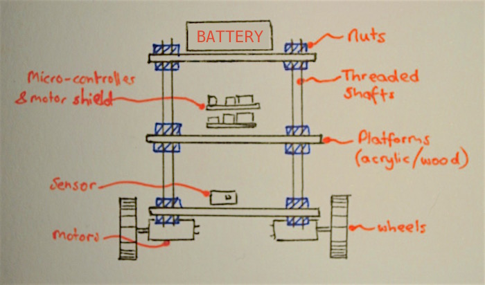
Fig:sketch of the self-balancing robot.
Components used in the Self-balancing robot
Before going to design the self-balancing robot it is necessary to list all the components that will use in the project.The components are as follow.
* Controller *
* Geared DC motors
* L298N Motor Driver Module
* MPU6050
* A pair of wheels
* 7.4V Li-ion Battery
* Connecting wires
* Acrylic Body
*wires
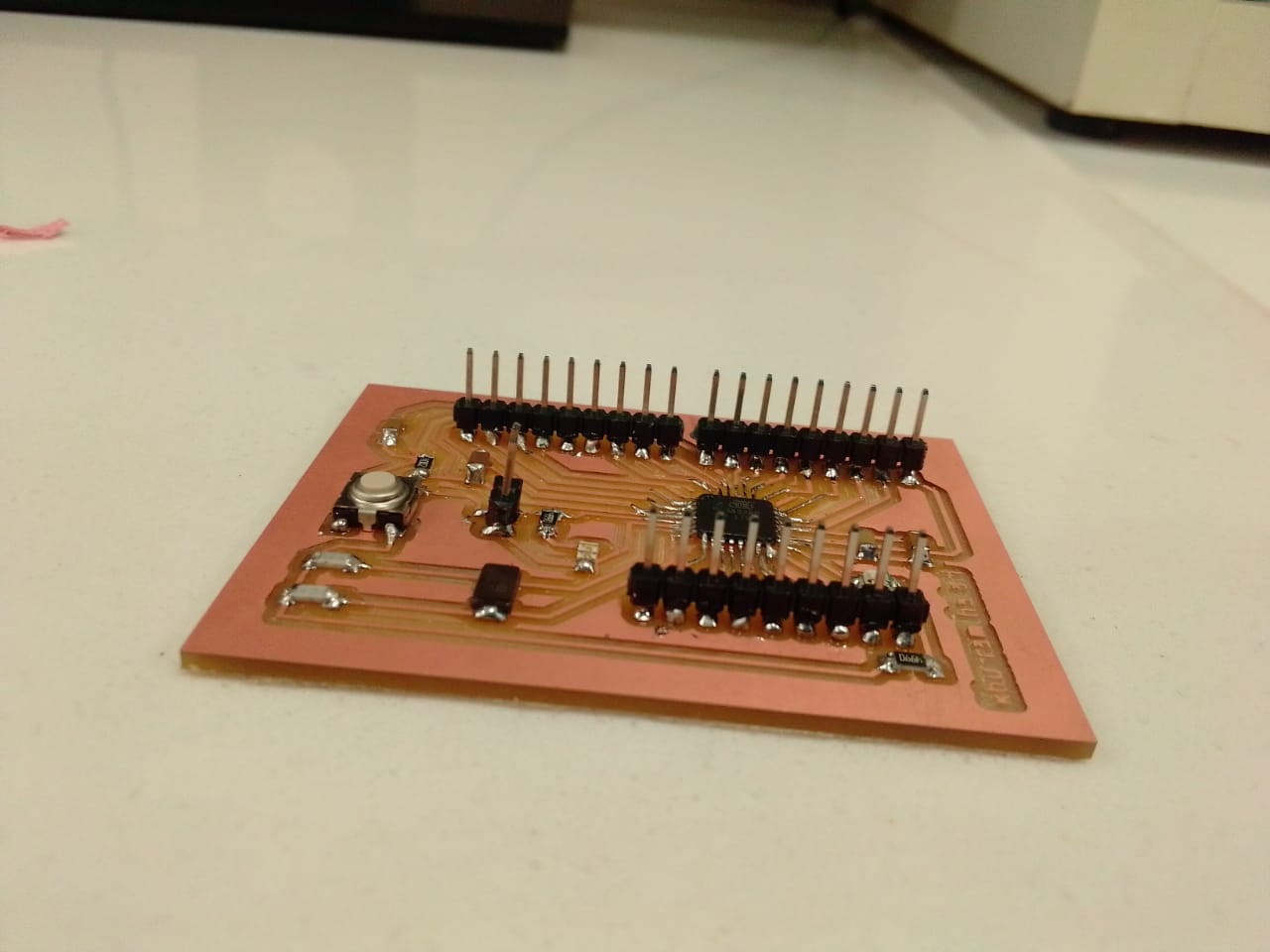
Controller
For the controller we use the satsha kit that we design and made in our own lab.
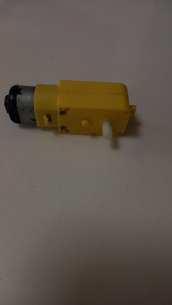
Motors:
There are may motors we can use for the self-balancing robot .In this we select the Dc motor for the robot.
Motor Driver:
As we have selected the DC gear motors so we can either use the L298N driver module ,
or even a L293D should work just fine.we select the L298N for our project.
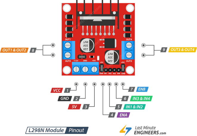
fig:picture showing the piout of L298N driver module.
Wheels:
While selecting the wheel it is necessary to make sure that your wheels have good grip over the floor you are using.
so we selact the wheel having grip that never allowour wheels to skit on the floor.
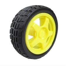
fig:the wheel having grip that use in our project.
Accelerometer Sensor mpu6050 :
The best choice of Accelerometer and Gyroscope for our bot will be the MPU6050. we got the idea of using this
after reading and understanding the article MPU6050 with Arduino.
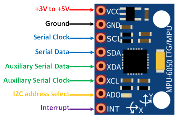
fig:The pin configuration of accelerometer sensor.
Battery
we are using the 3 lithium ion 4v cell
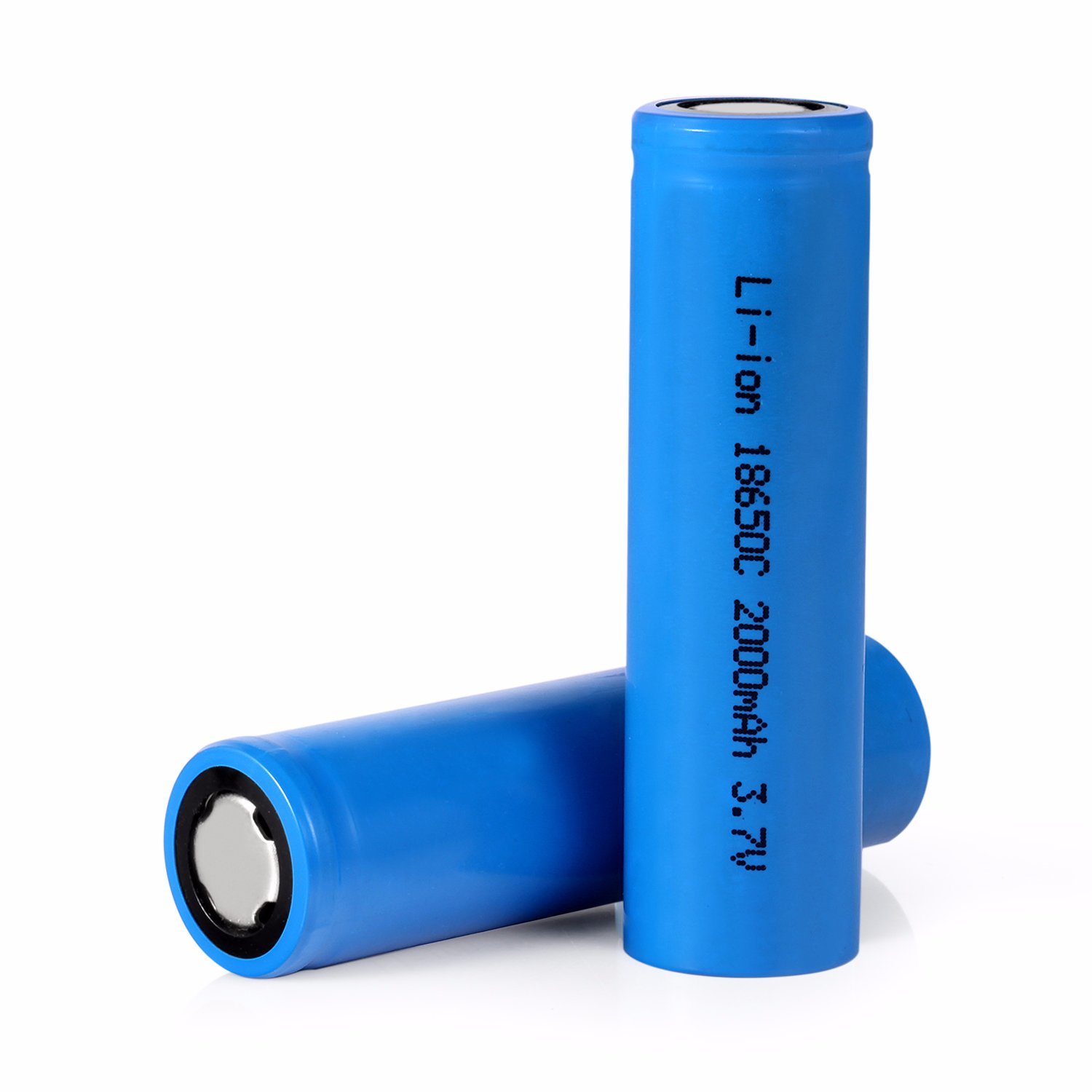
fig: screen shot of the cell use in the project.
Chassis and support for the self-balancing robot
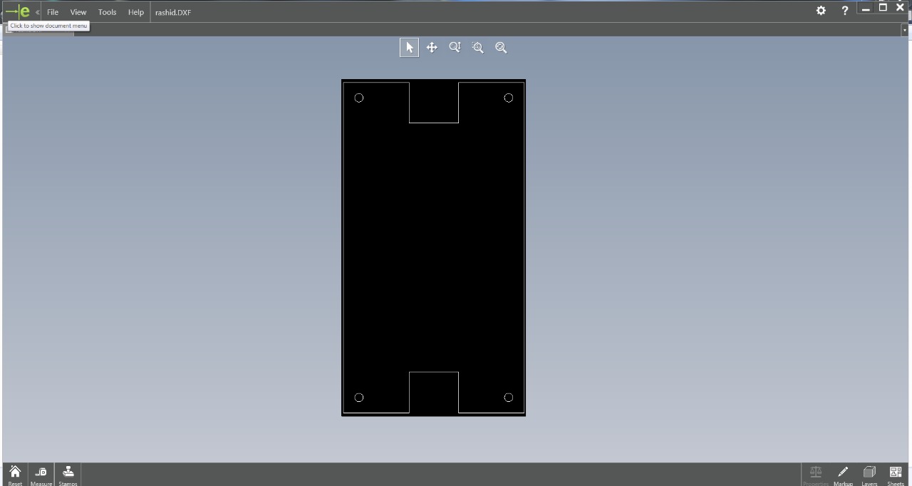
We design the the chassis and the support for the robot ain the solid work then we cut through the laser cutter.
so starting from the beginning :
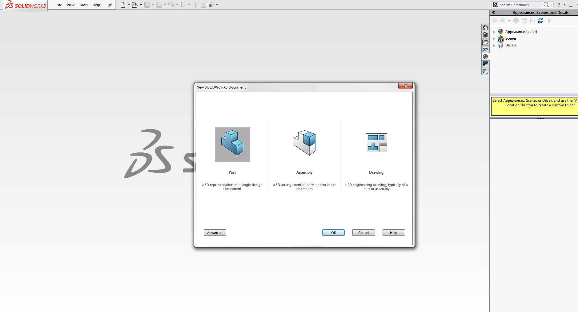
Fig; opening the solid work.
fig: screen shot of the base for the motor driver.
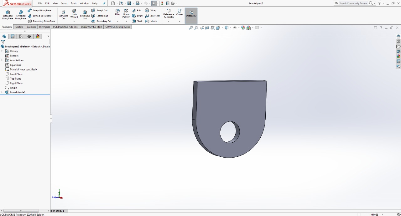
fig: screen shot of support wheels.
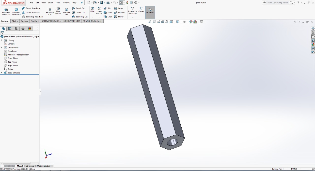
fig: screen shot of the pillar used as support for the chassis wheels.
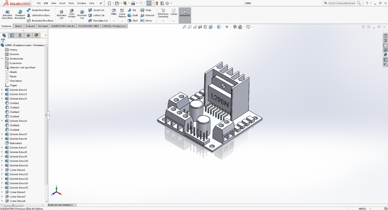
fig: screen shot of openning the motor driver in solid work.
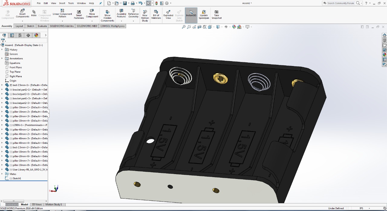
fig: screen shot of the battery holder
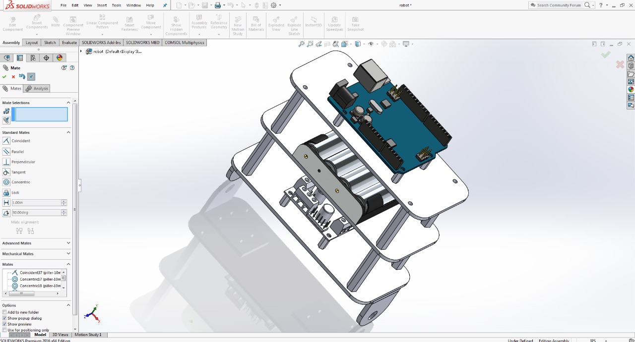
Now assemble all the part to see the final 3d view of the Self-balancing robot
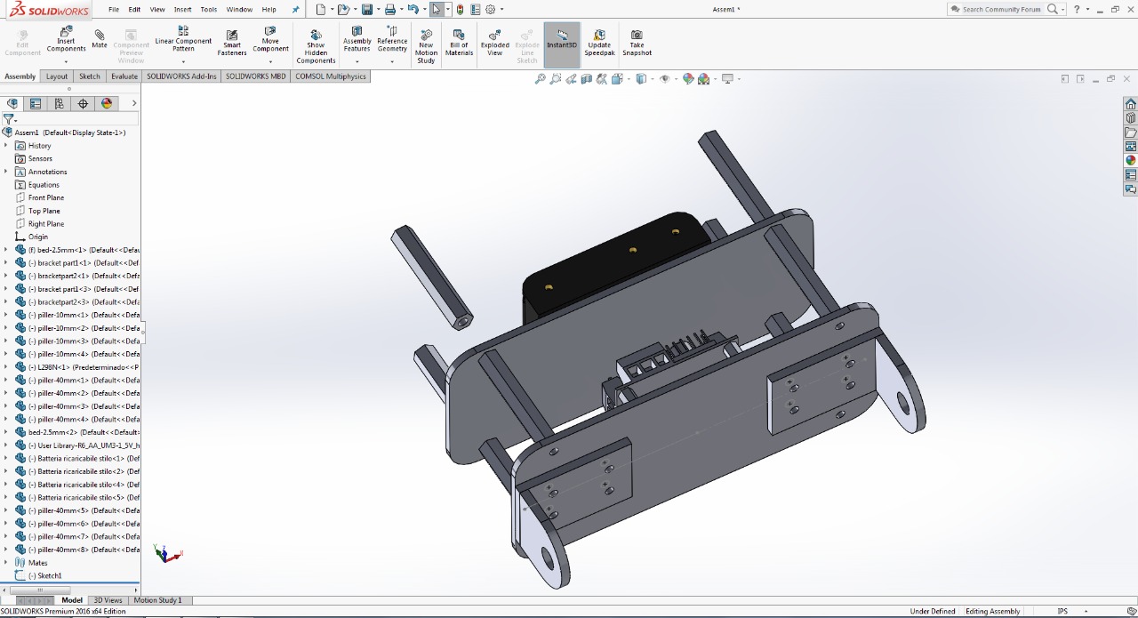
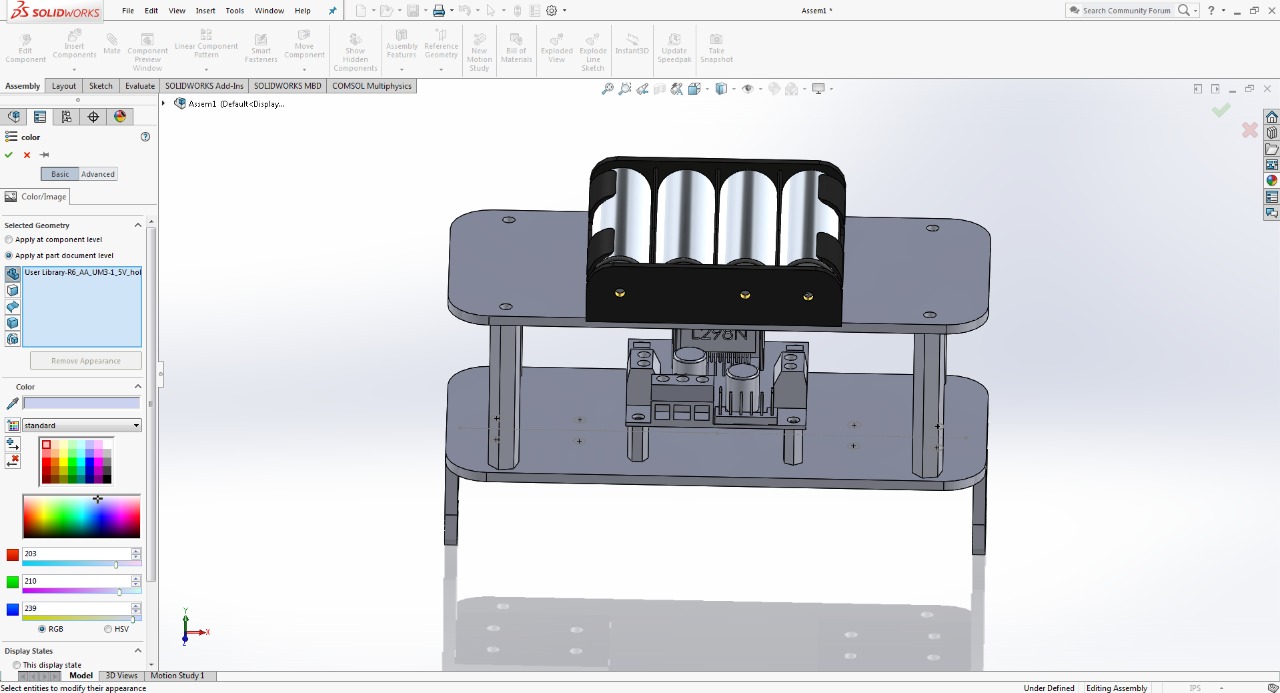
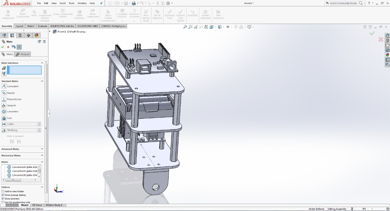
fig: screen shot of the opening and mating different parts of the robot in solid work.
the final look of our self-balancing robot will look as:
After designing the model in the solid work we moved toward the laser cutting machine to cut the parts of the projects.
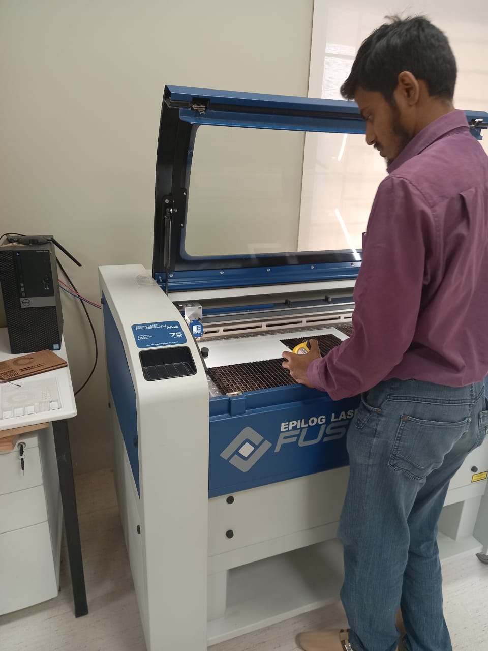
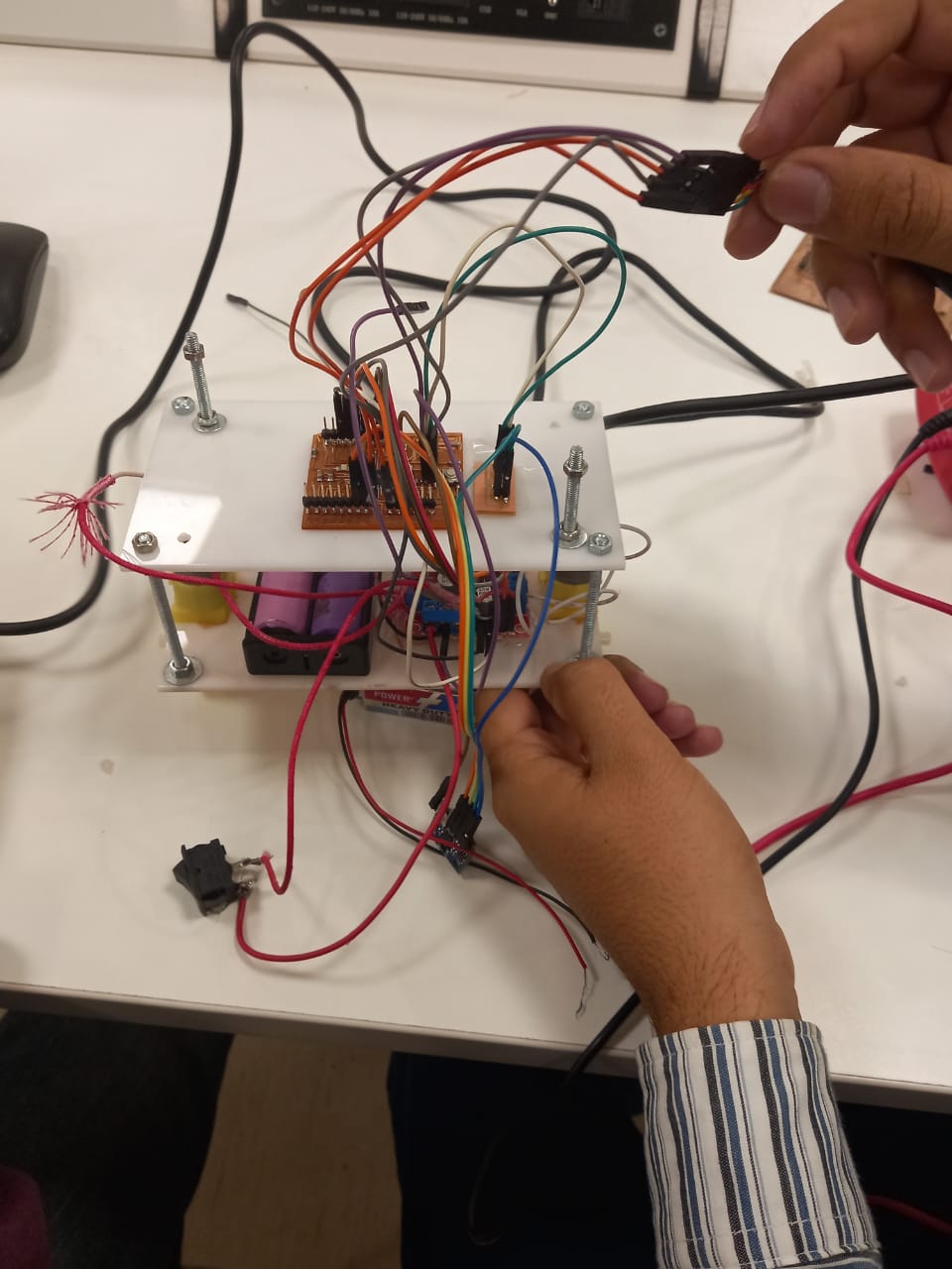
once the cutting is done we aseemble the parts and add the electronic components and wirring the project.
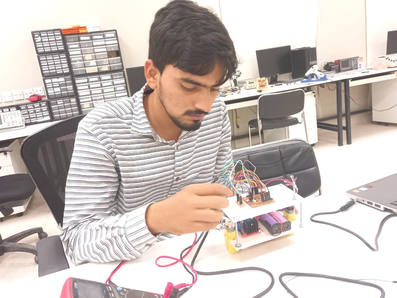
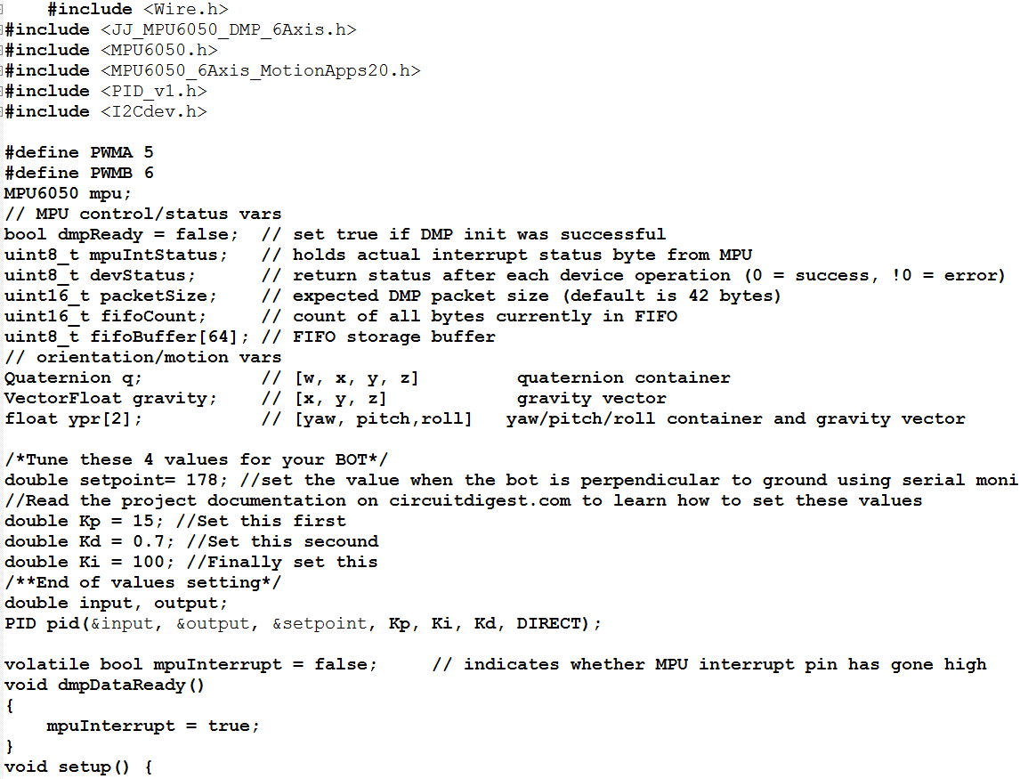
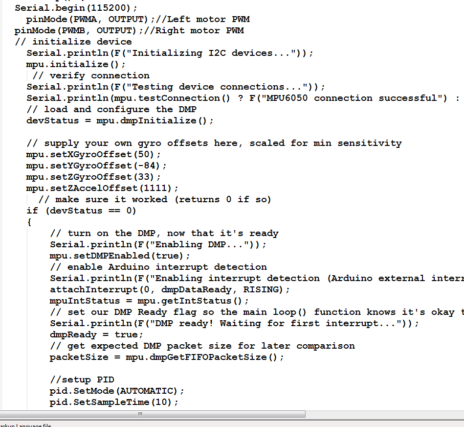
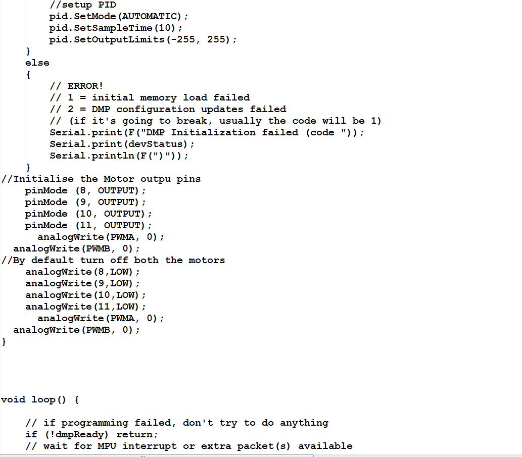
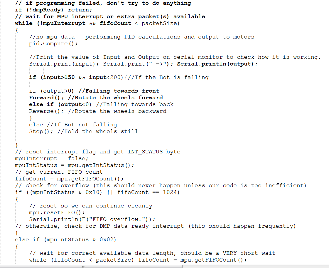
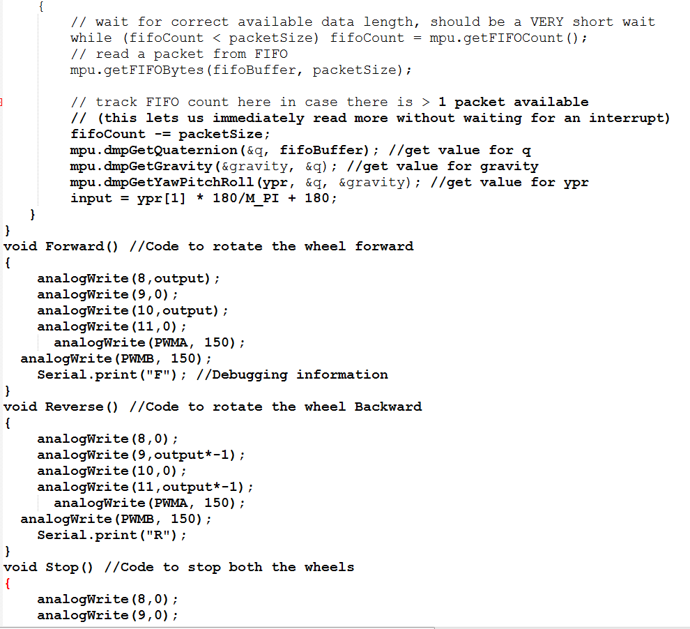
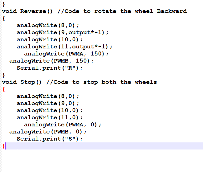
Now we upload the programming