
Group Assignment
Design a machine that includes mechanism + actuation + automation, Build the mechanical parts and operate it manually. Actuate and automate your machine,Document the group project.
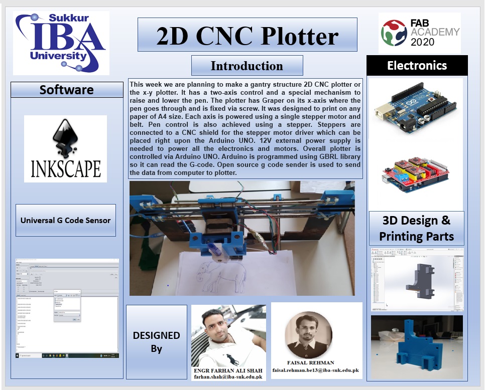
2D CNC Plotter
This week we are planning to make a gantry structure 2D CNC plotter or the x-y plotter. It has a two axis control and a special mechanism to raise and lower the pen. The plotter has graper on its x-axis where the pen goes through and is fixed via screw. It was designed to print on any paper of A4 size. Each axis is powered using a single stepper motor and belt. Pen control is also achieved using a stepper. Steppers are connected to a CNC shield for the stepper motor driver which can be placed right upon the arduino UNO. 12V external power supply is needed to power all the electronics and motors. Overall plotter is controlled via arduino UNO. Arduino is programmed using GBRL library so it can read the G-code. Open source g code sender is used to send the data from computer to plotter. all documents and detail are FAB LAB KHAIRPUR Machine Design Week.
Gantry structure
A gantry is defined as any of various spanning frameworks, as a bridge-like portion of certain cranes. In other words, it is a structure that bridges over an area. Like gantry cranes, the word is often used to refer to a structure that moves on wheels, often riding on a set of parallel rails. For more example on gentry CLICK.
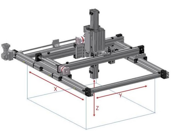
Model of our plotter
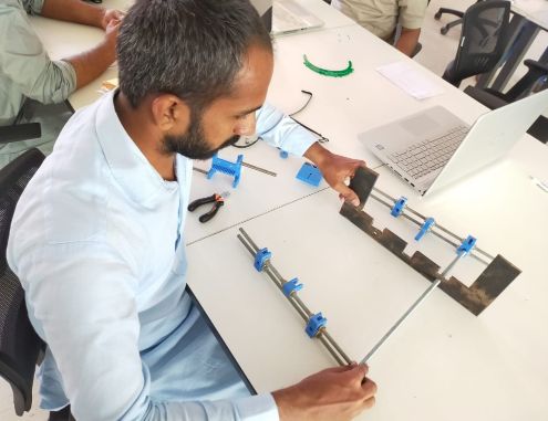
The present model is the first prototype created for gantry structure CNC plotter with steel rode and 3D parts. There are still several problems to solve, mainly of precision, and on the other hand there are also many ideas that can be made from this model. Our model consist of 3D printed parts along with metal rode and threaded rods. 3D printed parts are used to join metal rods and also used to fix the motorr.End factor is completly made of 3D printed parts.
3D Design
3D Design parts,We have designed in Solid work and we have divided our work into Two parts some of the parts were designed and Printed by my Group Mamber Farhan Ali Shah. and some were designed and Printed by me. So here these parts are designed in Solidwork.So I have started work from the STAND FOR THE X AXIS MOTOR and to the Pin holder.
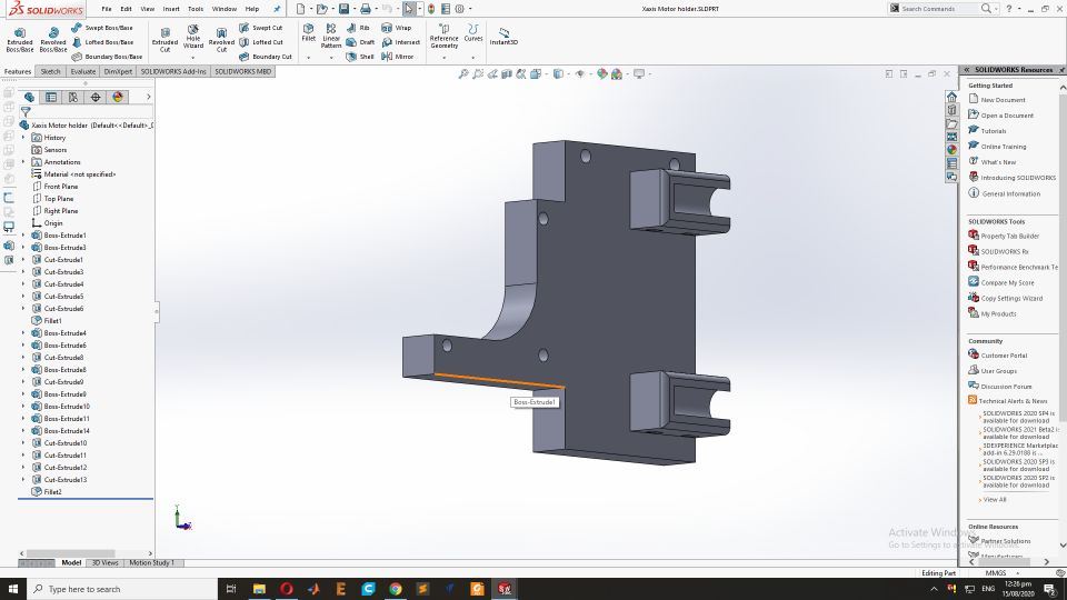
Stand for the X axis Motor
Now design the Stand for the X axis Stepper motor by above same process in solid work. This is the final resul
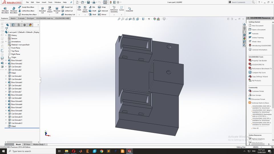
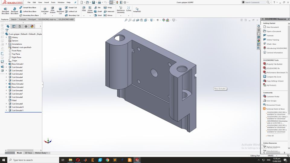
Pully stand on the opposite side of for the X axis Motor
This is part of X-axis. It lays in the opposite of X-axis motor where belt of X-axis will be connected with pully.
Z-axis motor connecting part
This part will be connected with Z-axis motor on which end factor(pen holder) will be placed.
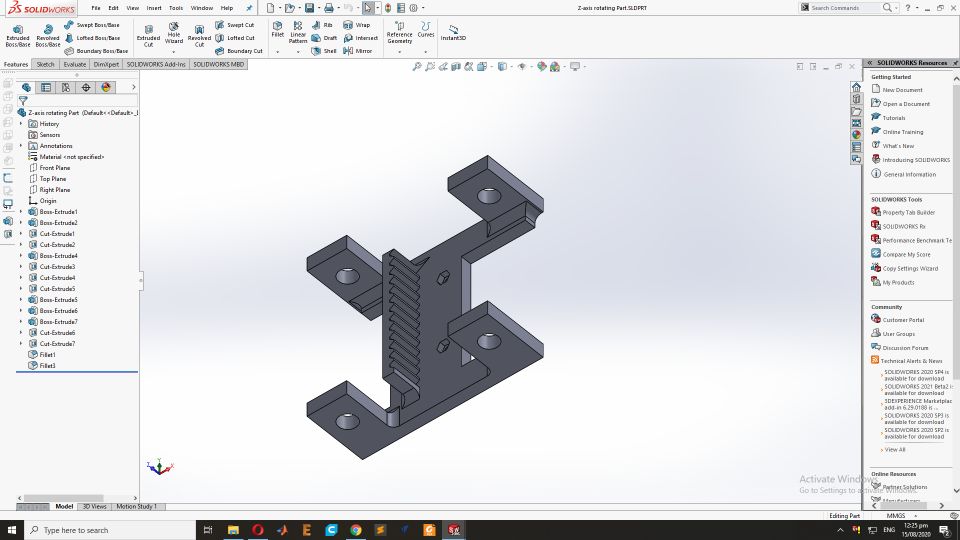
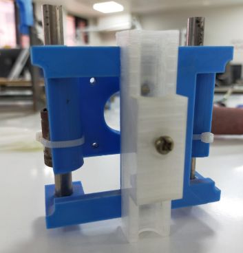
Moving part of Z-axis
This part will be connected with above part and pully on the z-axis motor will make it move up down.
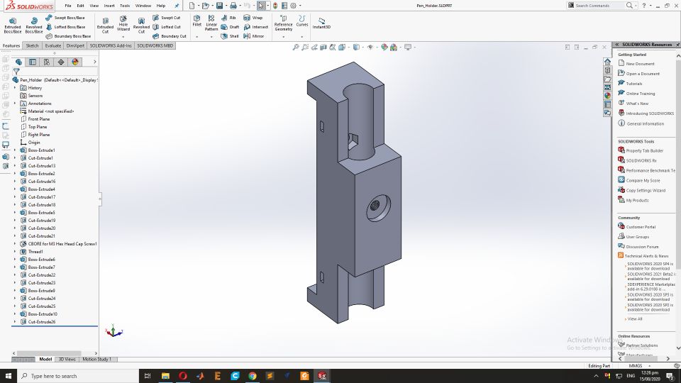
Pen holder
This part will hold the pen. Using screw pen will be fixed. This part will be connected with above part to make complete end factor.
Assembly
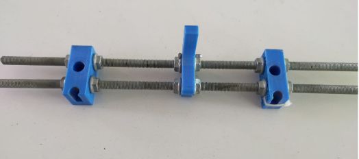
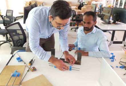
The Assambly Process we have work to gether to assambled it so First we need to setup the threaded rods and 3D printed parts. Insert the 3D printed parts into the threaded roads for the base and pully support.for more detail FAB LAB KHAIRPUR.
the Second side of the base stand for the Stepper motor that used as the Y axiss.
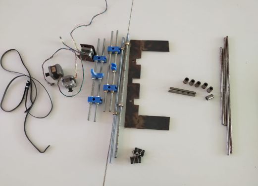
this is the overall Iron material required for the 2D CNC plotter and with steper motors.
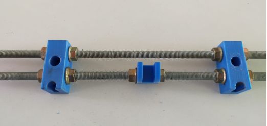
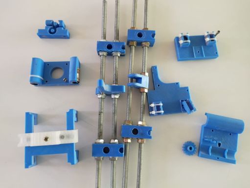
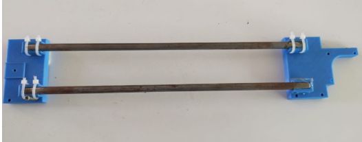
3D printed parts after printing and Assembling the with threaded rods
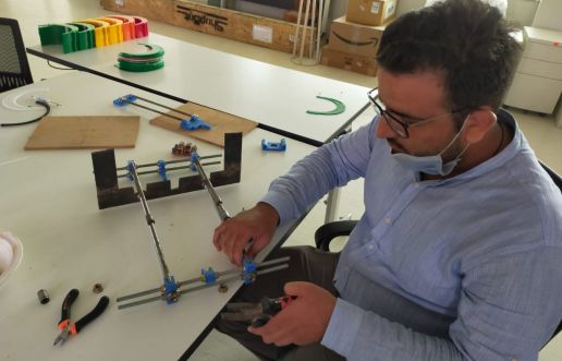
Now we have start to assamble the base of the plotter so first we have assembled Iron rodes with 3D stand parts and then fixed with U shaped Stand.
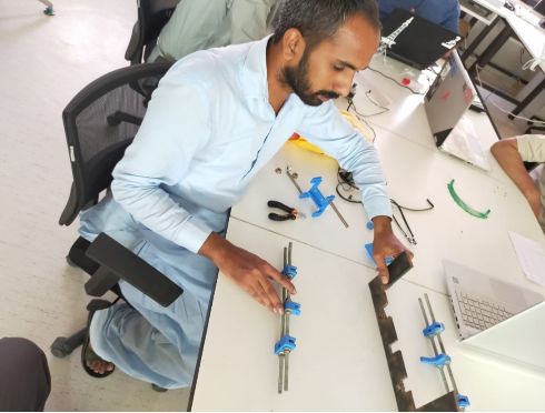
While the Assambly of the Base.
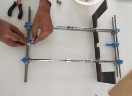
We have fixed base stand and rodes with Nuts.
Fixed the stand with nuts. Now the Base of Plotter is alomost ready.
Now we have fixed the Pully for the Y axis.
Now time to fixed the Stepper motor for the Y-axis movements.
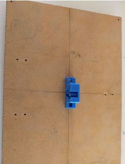
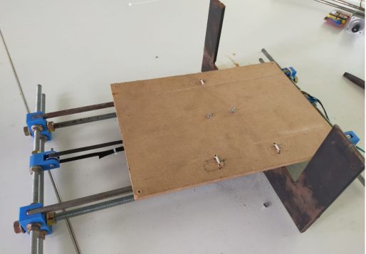
This is the Paper stand where paper is fixed for the sketch.
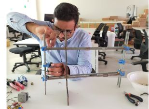
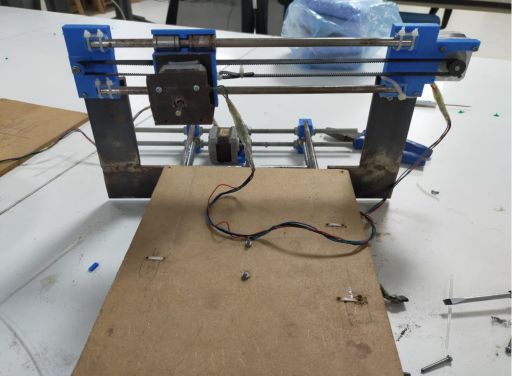
We have complete the Gantry Structure of the 2D plotter.
Now we have fixed the Stepper Motor for the X-axis dircetion. This is the upper Arm after the fixing the Iron Rods.
Now we have fixed upper Arm with the Plotter Stand.
After the Fixing the Upper Arm now we have also fixed the Stepper motor for the Z-axis(end factor motor).
Assembly for end factor(Pen holder). This will be fixed to the z-axis motor.
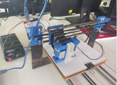
Complete Assembly
Manual working of plotter
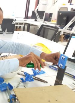
For the manual we have move the all dimenissions to check that the designed Plotter is working well.Here is demo given and other details given FAB LAB KHAIRPUR.
G-Code Generation
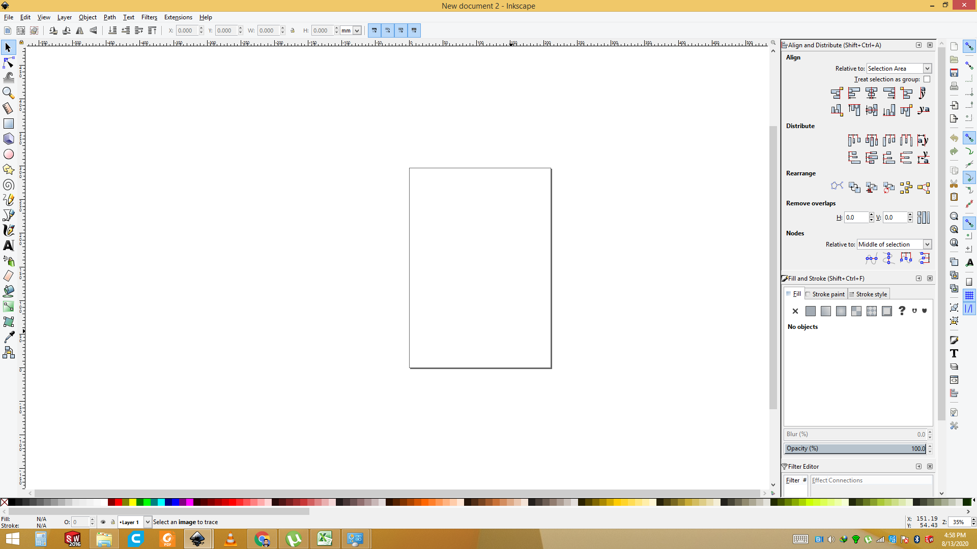
This is also my part and I have use the inkspace software to generate the G-code. Open the Inkspace software
Import the Image that you want to plot.
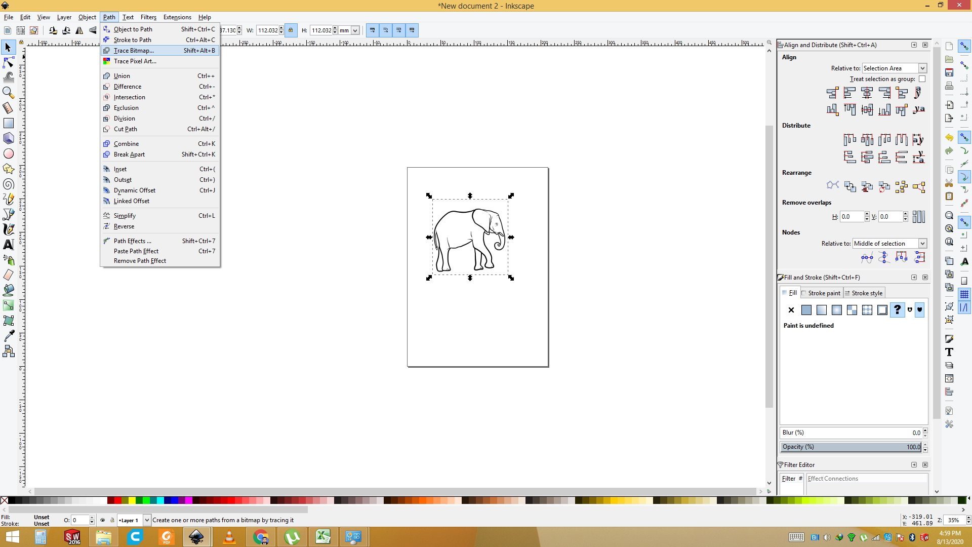
Now we have set the Bit map trace to generate the Vector of the Image.
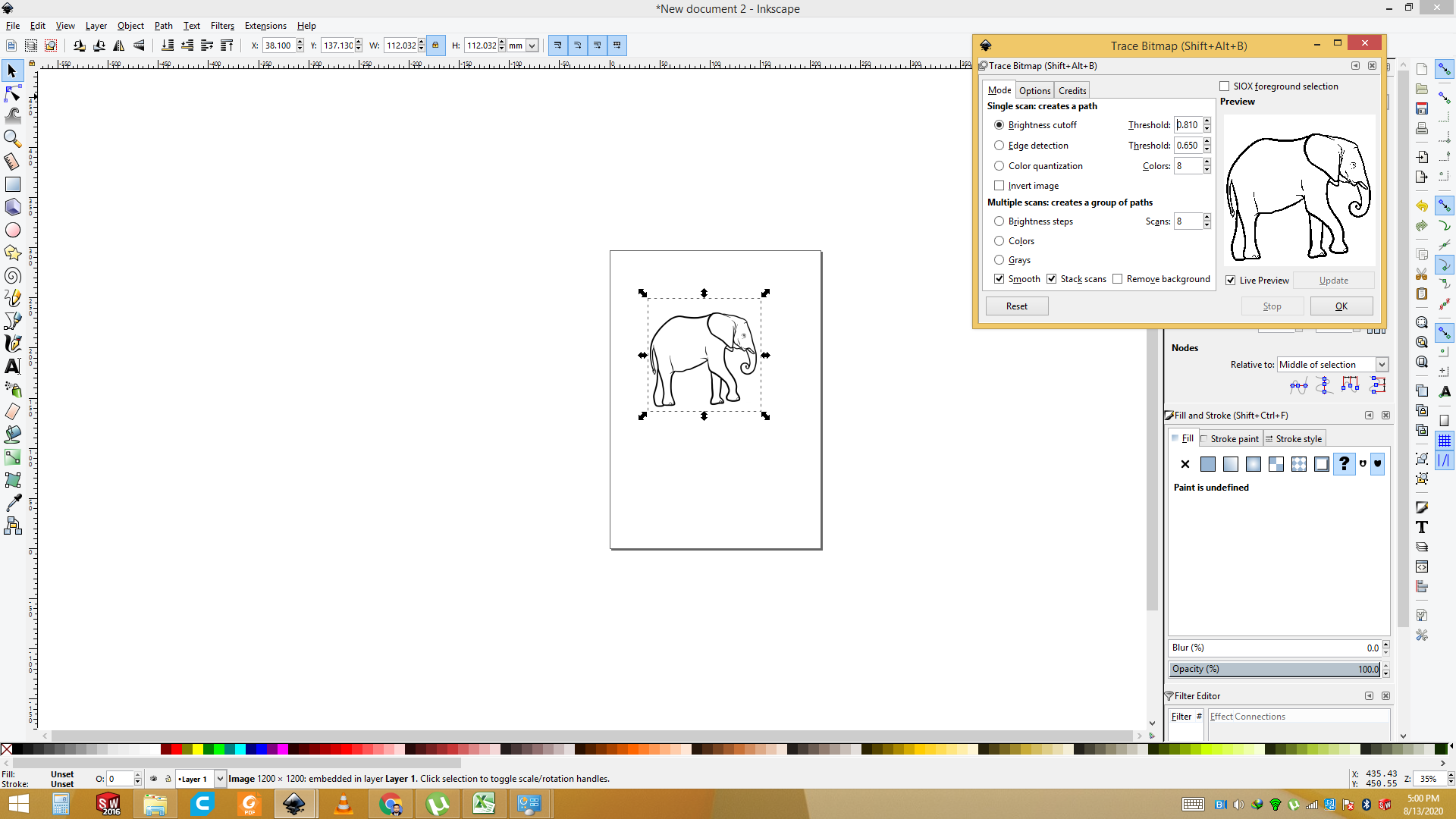
Go to the Tool and select the Bitmap trace and press OK command and add to the layer .
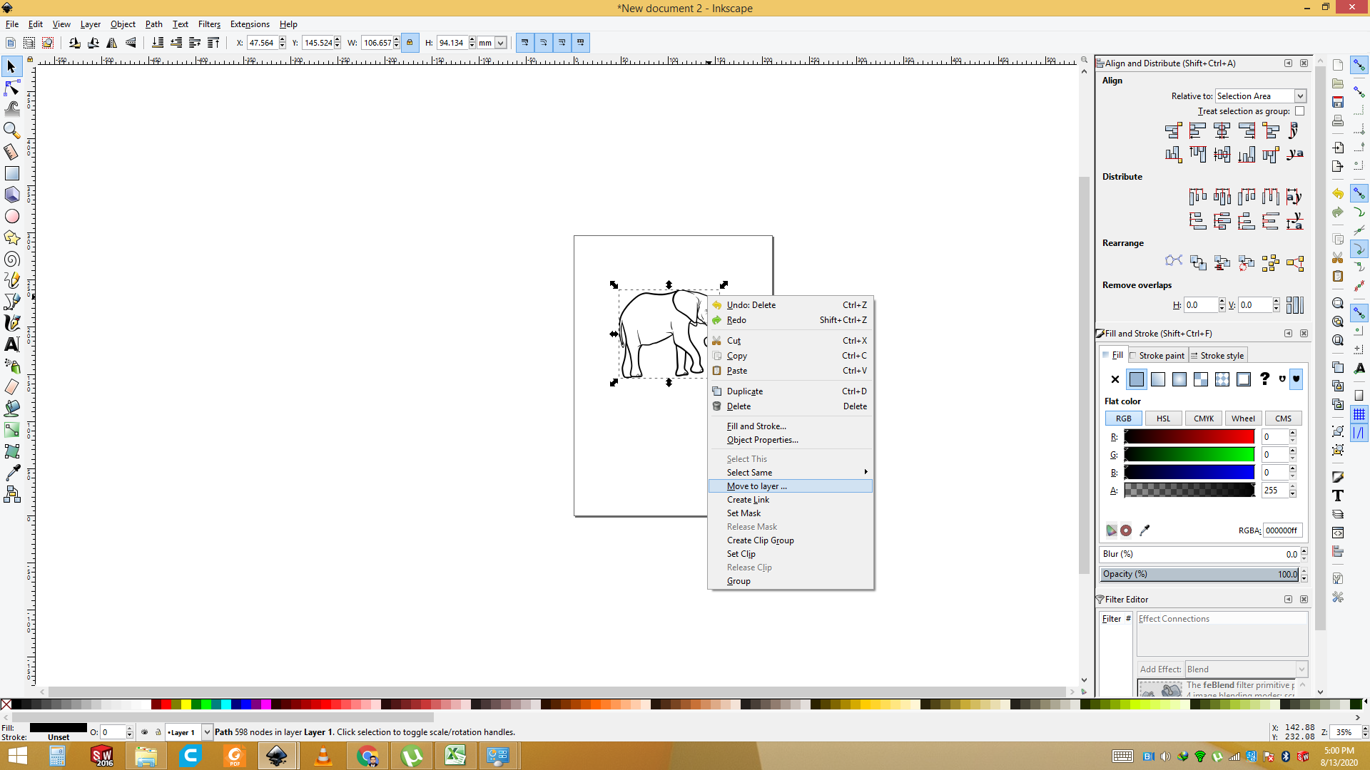
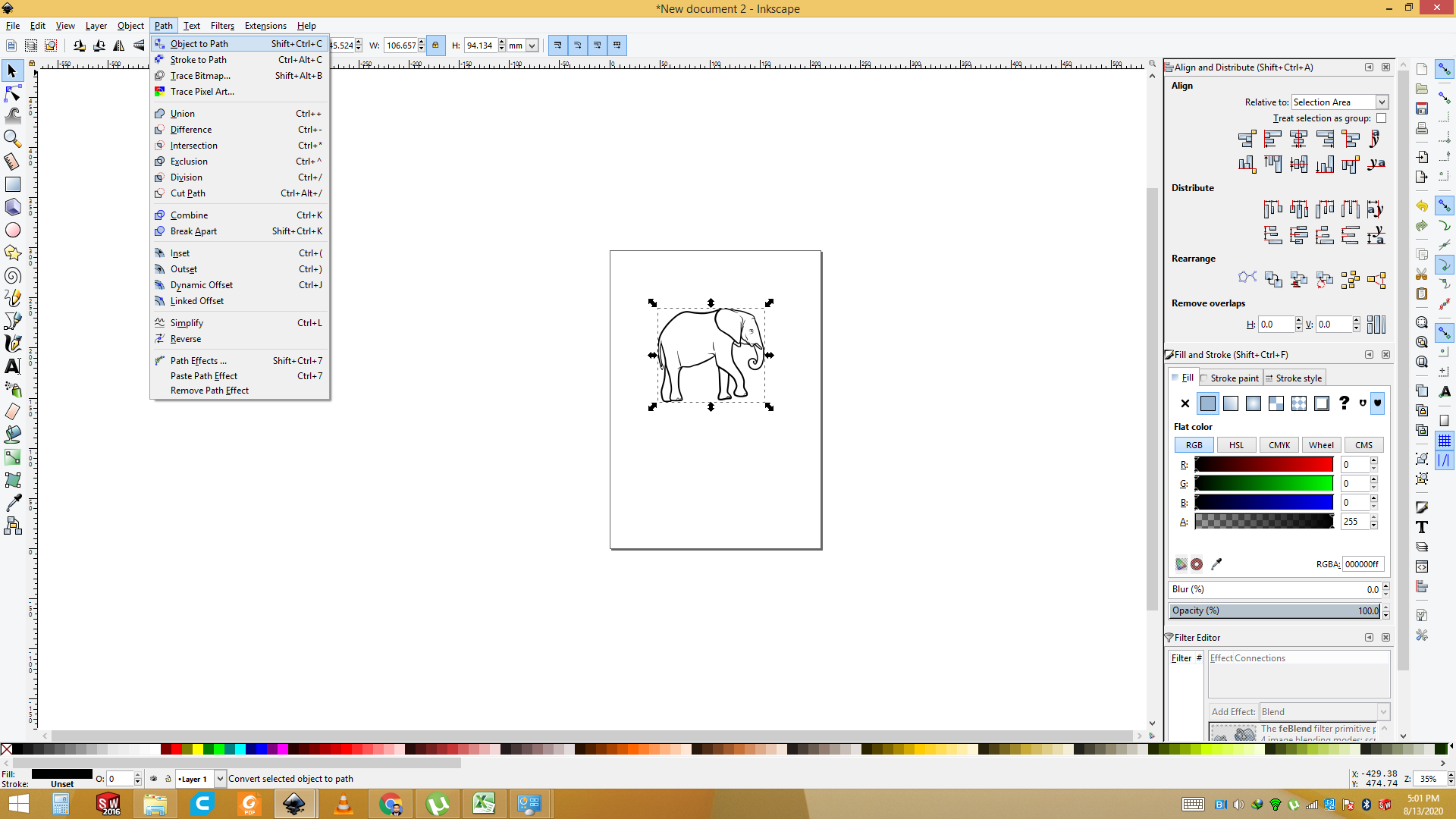
Now add the Object to path so first select the Image then go to path and select the "add to the path".
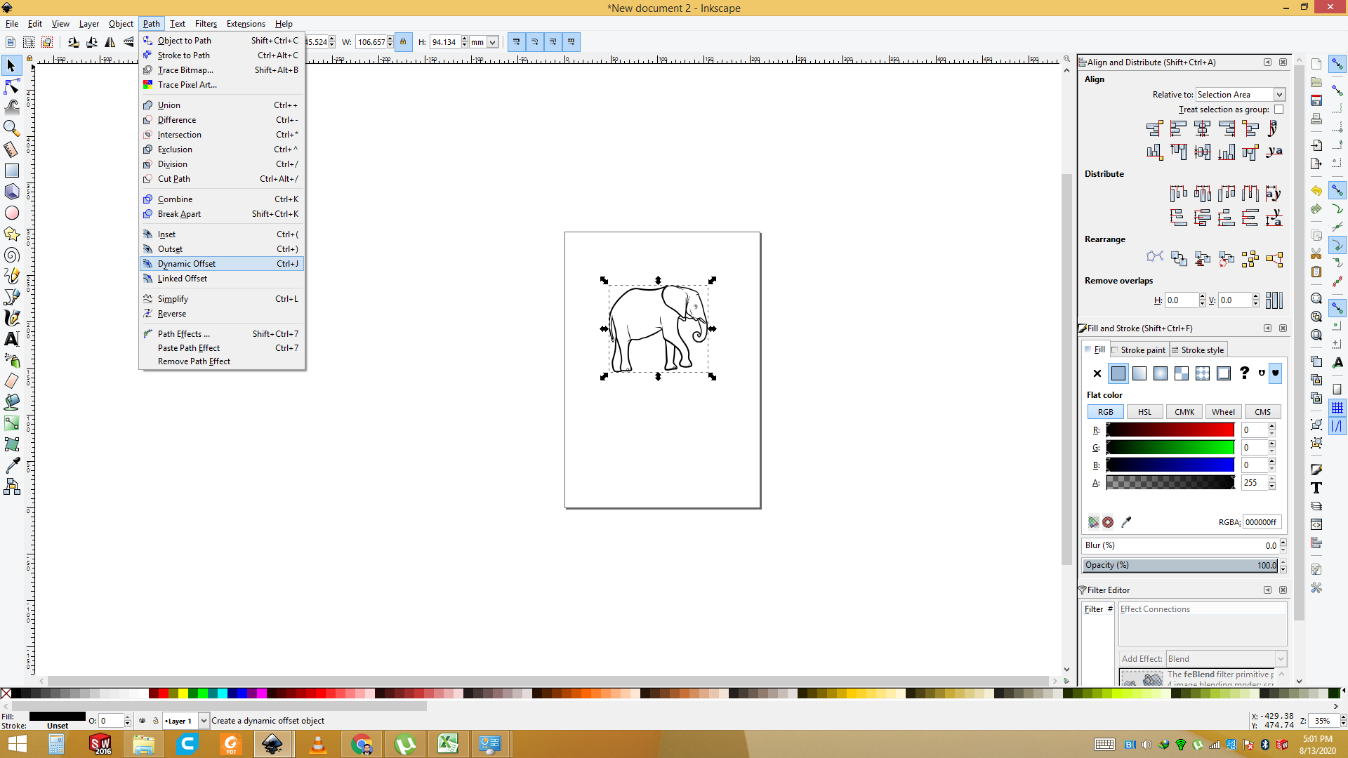
Now go to the path and select the dyamics Offset or press the "ctrl+J".
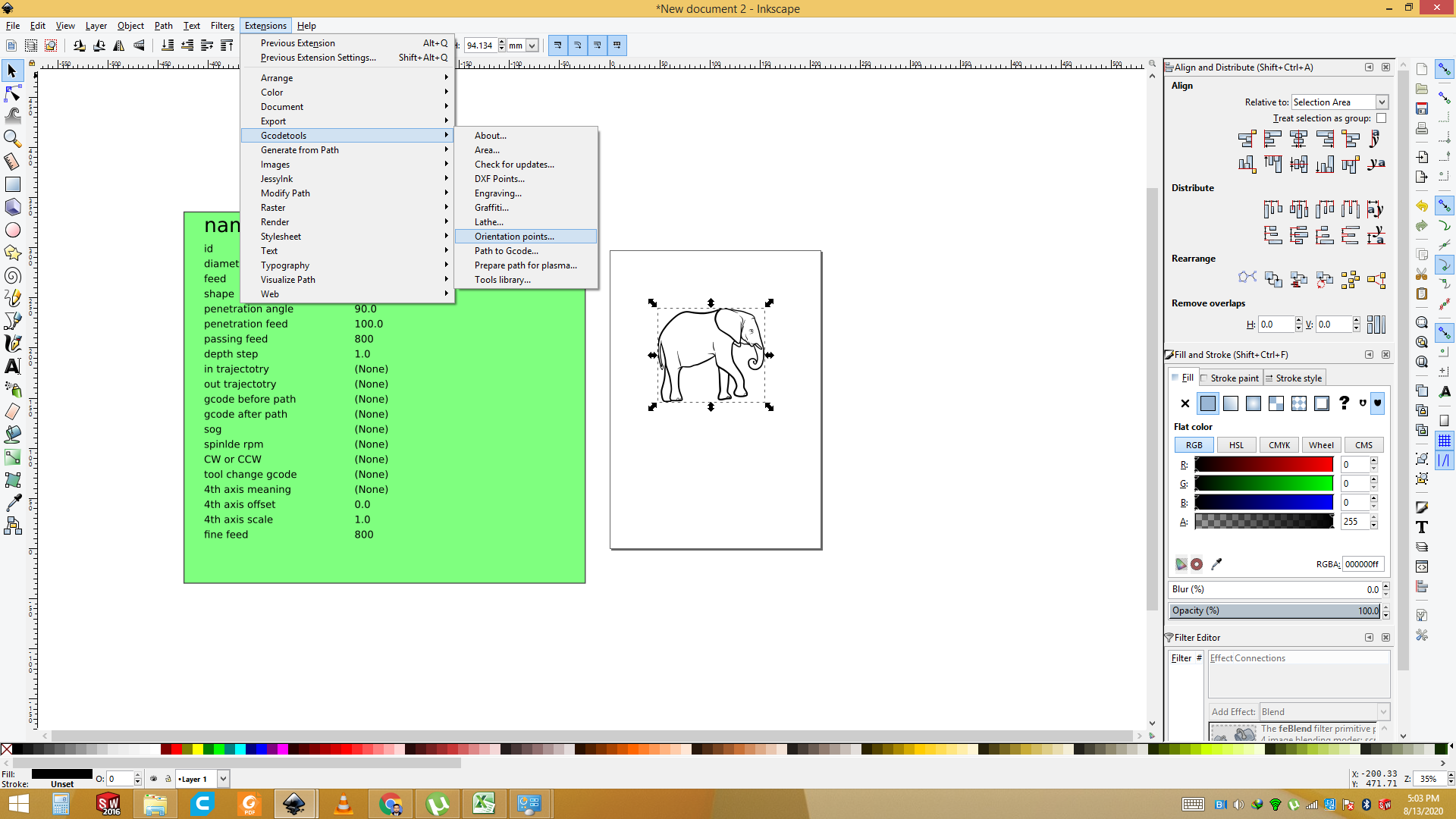
Now go to the Extension sand select GcodeTool for the G code generate.
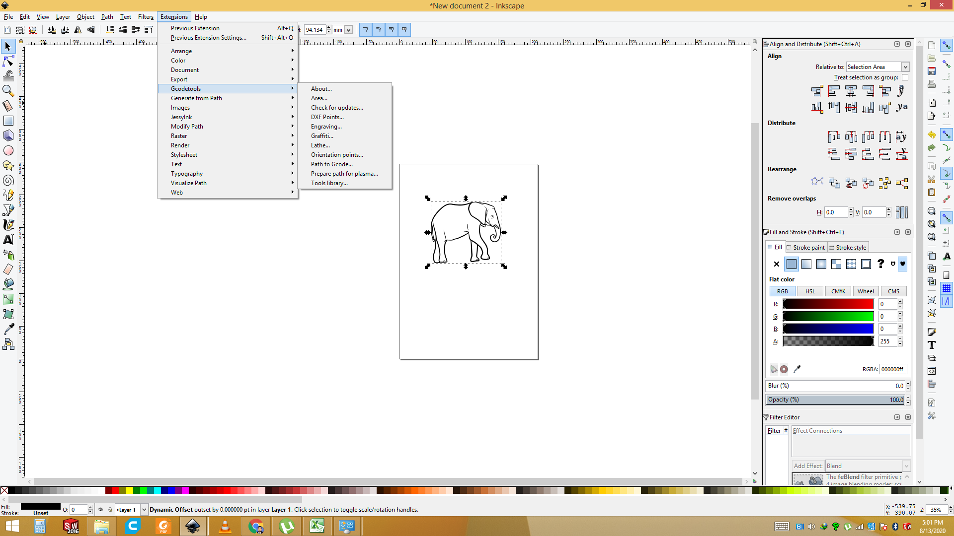
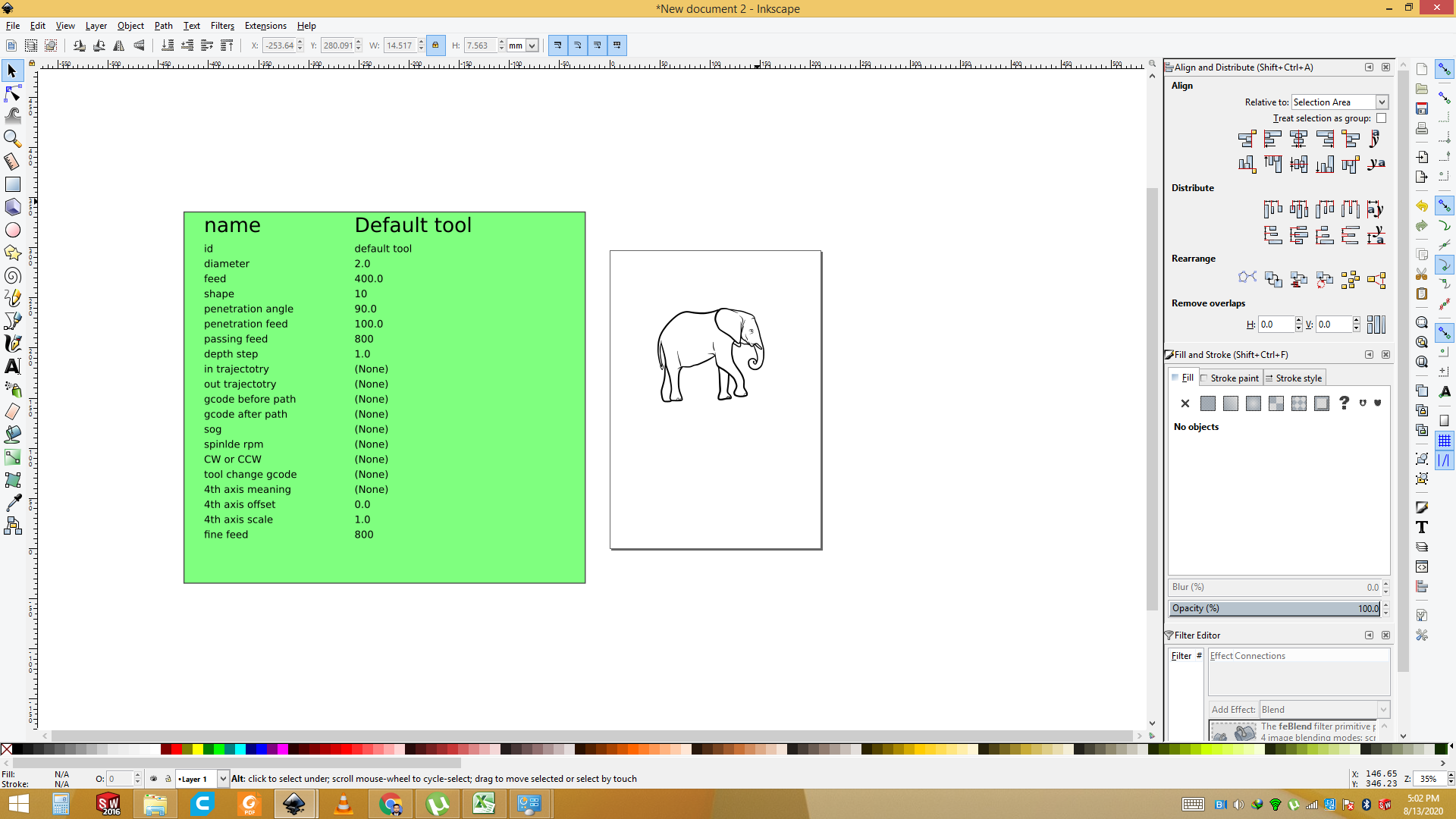
Now go to the Extension sand select GcodeTool and Select the " Tool library ".

Now set the diameter " 2.00"
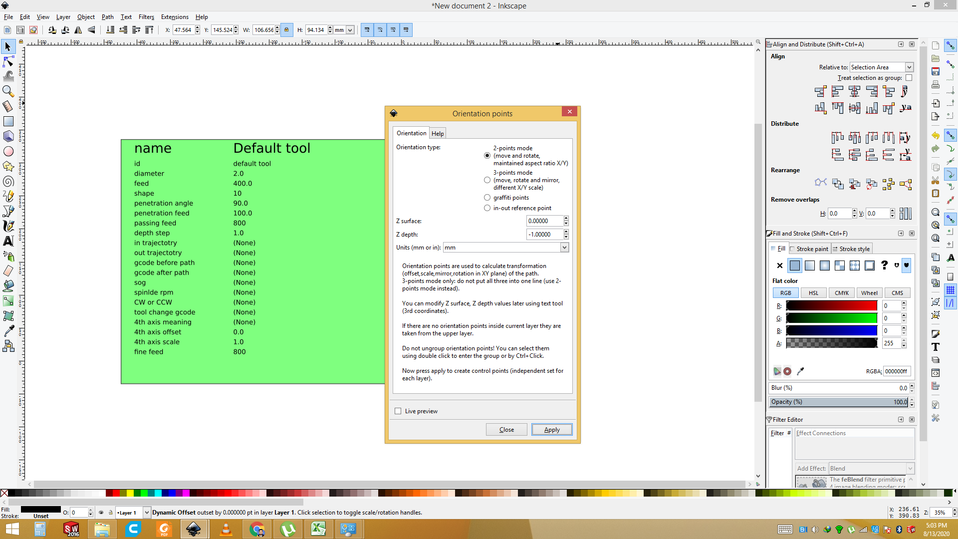
Goes to the Extension and select the "G code Tool " and set the Orientation point of the Image.
set the Orientation point of the Image and Apply it.
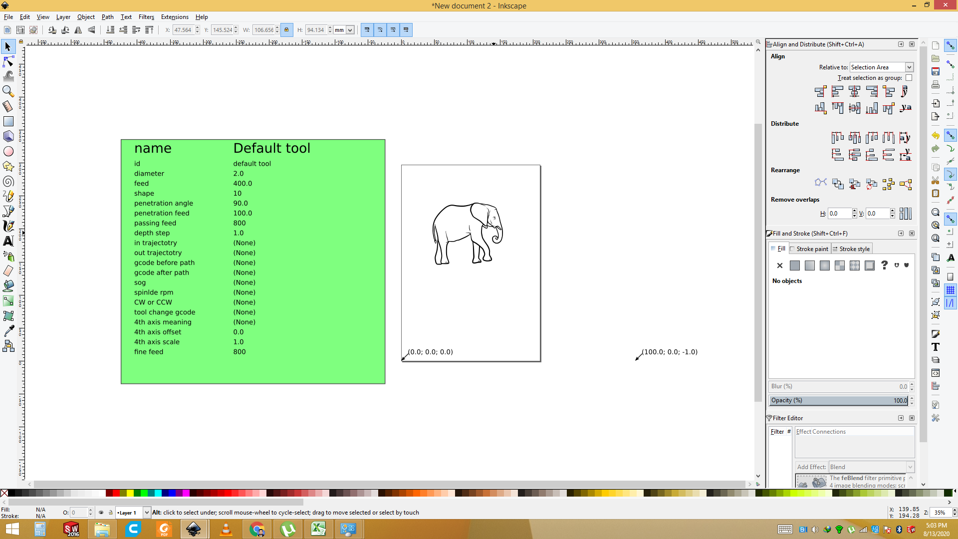
the result of the set the Orientation point of the Image.
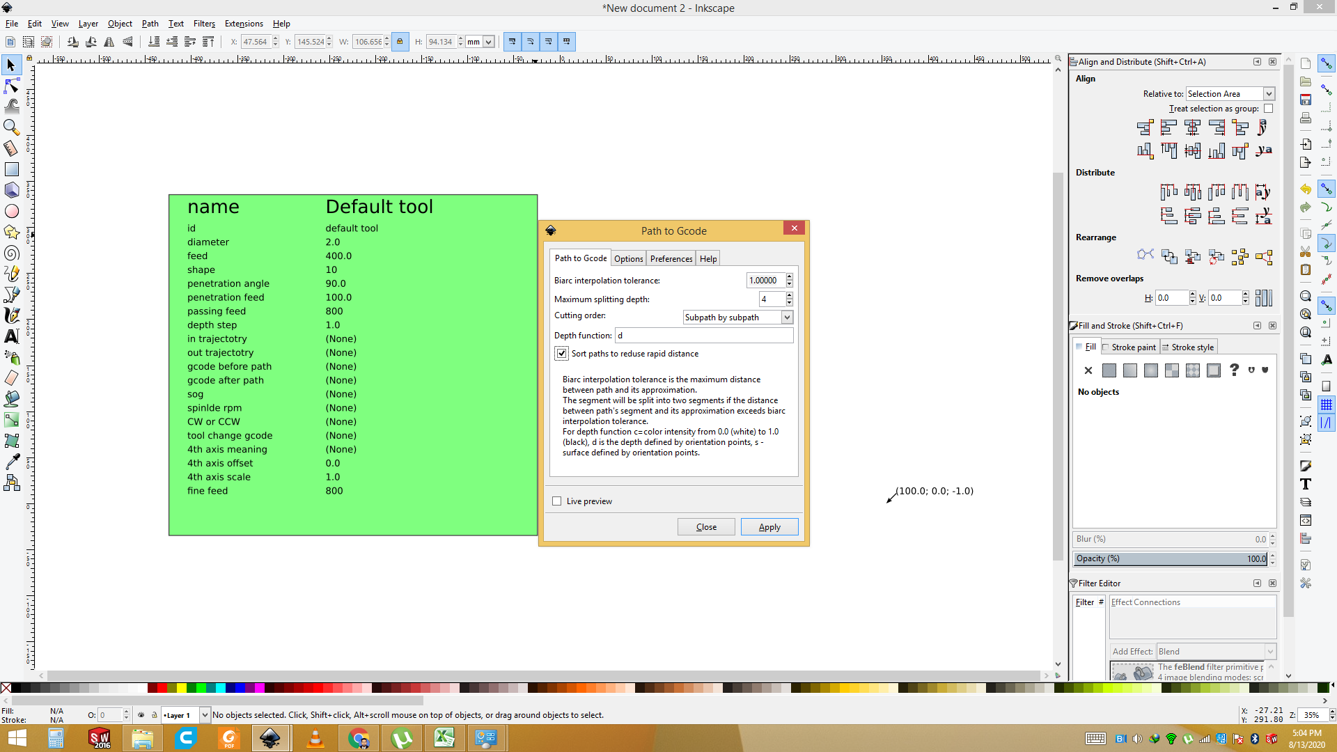
Goes to the Extension and select the "G code Tool " and set the path to G code.
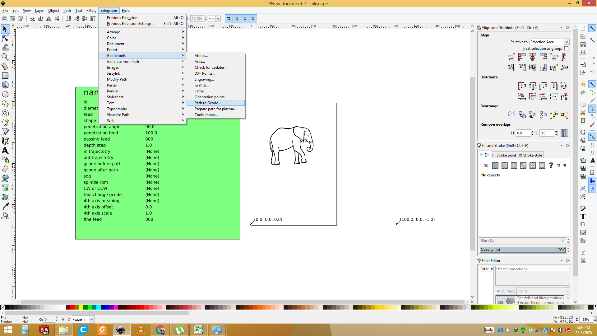
Now Press the Key "apply".
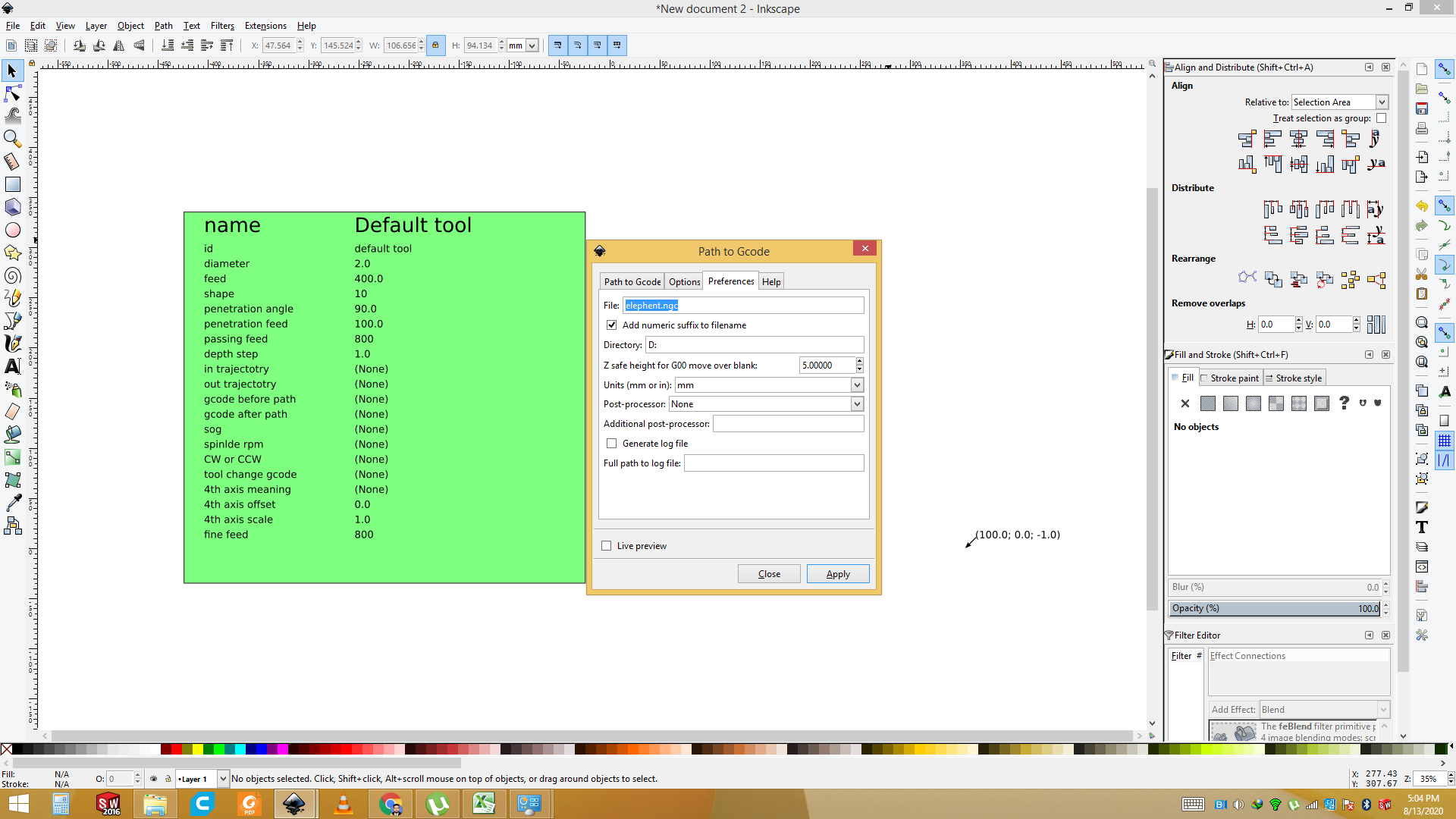
Now set the "Preferances " and name the file then apply it.
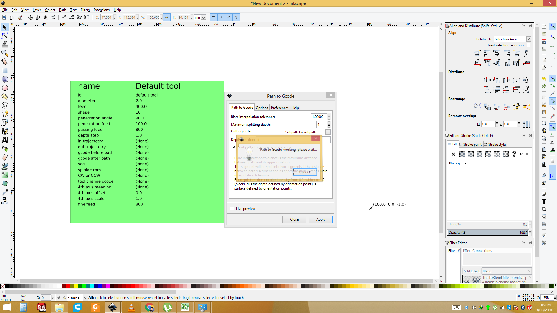
Now G code is generate and its working.
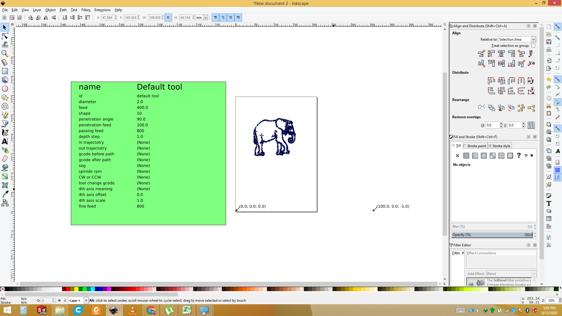
Now File is ready change the name save it.
DEMO
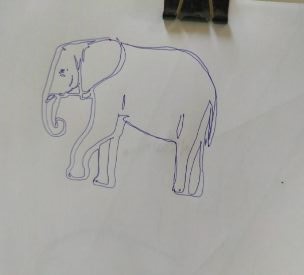
This the Demo in which 2D CNC Plotter is Printing the Elephant on the White paper.
Final Demo after the Printing.for Further more details are given on the FAB LAB KHAIRPUR MACHINE DESIGN WEEK.
Conculsion :
This week we have designed the Mechanical Design of the 2d CNC Plotter and also Design the 3D Parts and Also Print them, after that we have also tested it for the different images.and for more information and Complete documents are FAB LAB KHAIRPUR.
Improvements in Future
This is the first version of the plotter. It is working fine but can be improved in many areas. First thing which we want to see in future if any other person wants to work on it, is to add multiple pens in the header. It will be great thing to watch if the sketch made of multi-color pens. Automatically one pen goes up and the other comes down and starts sketching. Another thing is smoothness in movement. It is working smoothly but sometimes there is some jerk in it. Stepper motor can be replaced with BLDC motor for faster working. Writing area is A4 size. This can be increased as well.
Download All file of this week Here.

This work is licensed under a Creative Commons Attribution-NonCommercial-ShareAlike 4.0 International License