
Smart IoT based Energy Metering Devices using the ADE7757.
Project Introducation
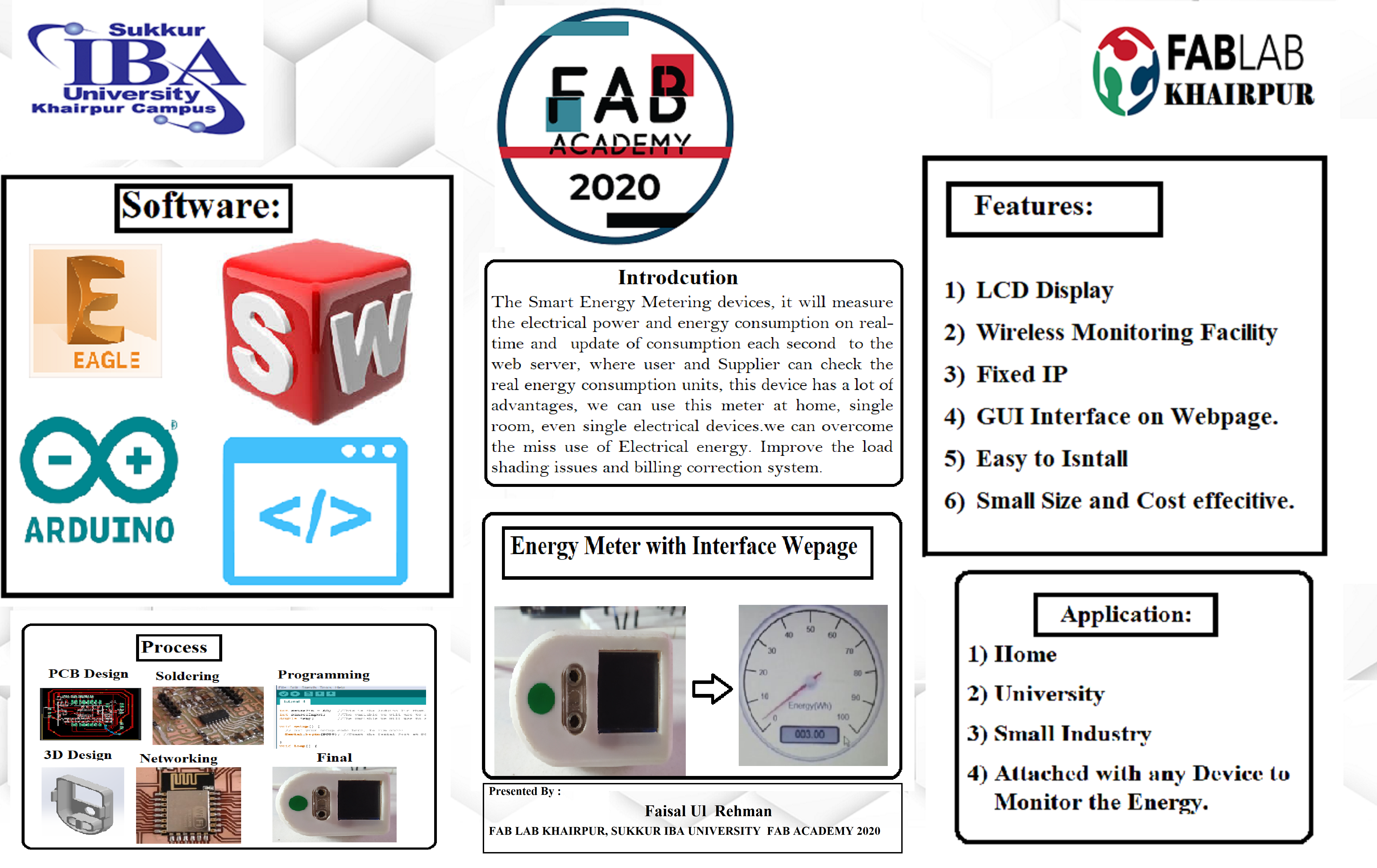
My project is to design the Smart IoT Based Energy Metering devices, This device will measure the electrical power and energy consumption on real-time and at update each second consumption on web server, where user and Supplier company can check the real energy consumption units, this device has a lot of advantages, we can use this meter at home, single room, even single electrical devices like AC, Iron, electric heater etc.by using this meter we can overcome the miss use of Electrical energy. Improve the load shading issues and billing correction system, we all are familiar with Android technology so it's very easy to every one can monitor their units.and they will try to don't miss use of Energy.
Poster Presentation of Final Project" Energy Meter".
Final Demo
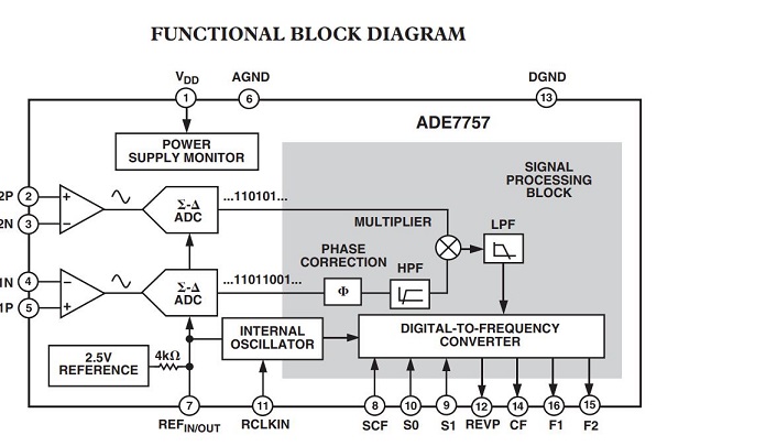
ADE7757- Signle phase Energy Monitoring ICS
The ADE7757 is a high accuracy electrical energy measurement IC. It is a pin reduction version of the ADE7755 with an enhancement of a precise oscillator circuit that serves as a clock source to the chip. The ADE7757 eliminates the cost of an external crystal or resonator, thus reducing the overall cost of a meter *U.S. Patents built with this IC. The chip directly interfaces with the shunt resistor and operates only with ac input.Here.
The ADE7757 specifications surpass the accuracy requirements as quoted in the IEC 61036 standard. The AN-679 Application Note can be used as a basis for a description of an IEC 61036 low cost watt-hour meter reference design.All other signal processing (e.g., multiplication and filtering) is carried out in the digital domain. This approach provides superior stability and accuracy over time and extreme environmental conditions.ADE7757 Single Phase Energy meter Data Sheet is Available
The ADE7757 supplies average real power information on the low frequency outputs F1 and F2. These outputs may be used to directly drive an electromechanical counter or interface with an MCU. The high frequency CF logic output, ideal for calibration purposes, provides instantaneous real power information.Here.
Internal phase matching circuitry ensures that the voltage and current channels are phase matched while the HPF in the current channel eliminates dc offsets. An internal no-load threshold ensures that the ADE7757 does not exhibit creep when no load is present.
Specifications & Features of ADE7757 IC:
The Energy Meter IC ADE7757 Data Sheet is Available for more Deatils HERE and I will use this IC to design the Energy meter.
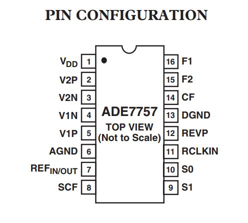
This meter IC has two channels that are Input AC Channel for the measuring the Power.
Input AC Channel:
Output Channel:
This is the circuit diagram of Energy meter ADE7757 IC which is help full for the design final project of Energy Meter. HERE
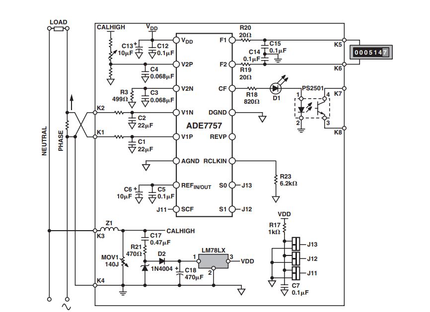
Now the phase is to design the PCB circuit using the Eagle CAD Software , First download the ADE7757 Library From HERE and add/install in eagle Software.
PCB Design :
The new phase is to design the electronics printed circuit board So I am working on the CAD Eagle Sofatware to design the Energy meter Board. as I also use in Electronics Design, and Electronics Production. also use an other weeks.
Few step are required for the CAD design.
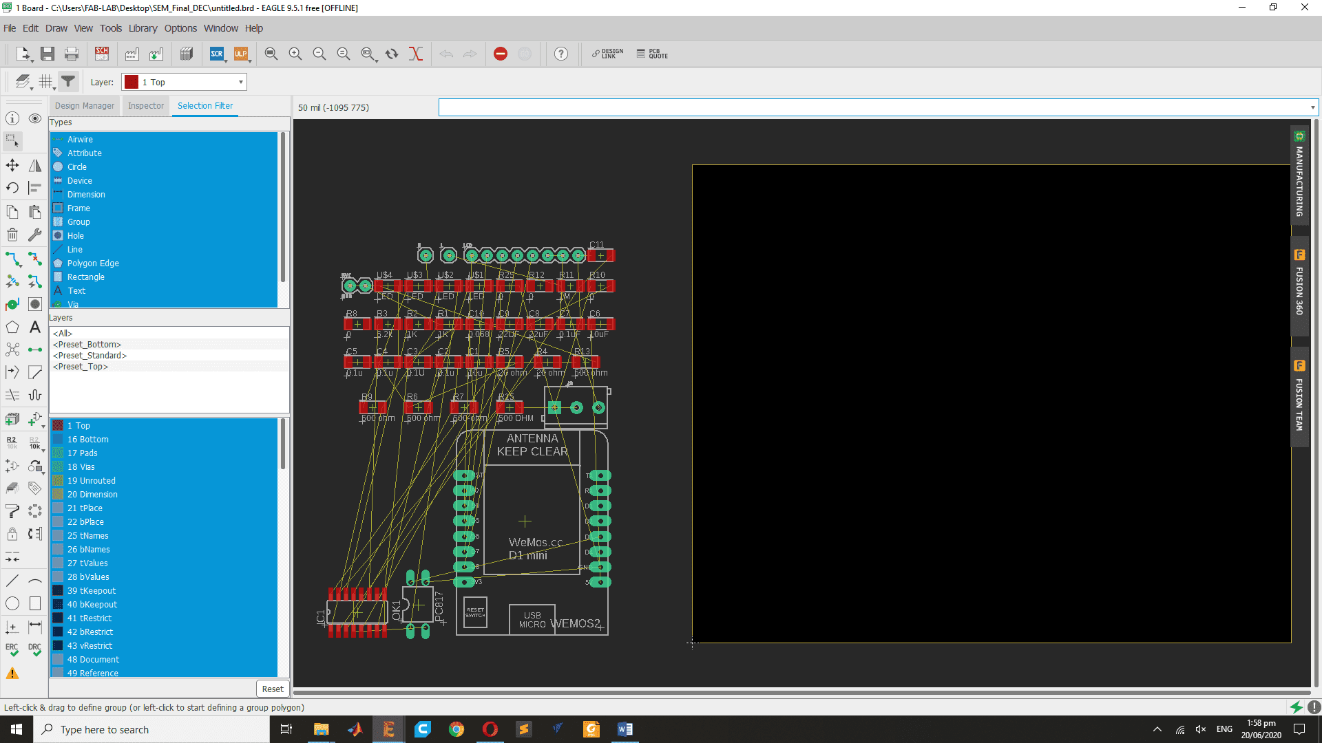
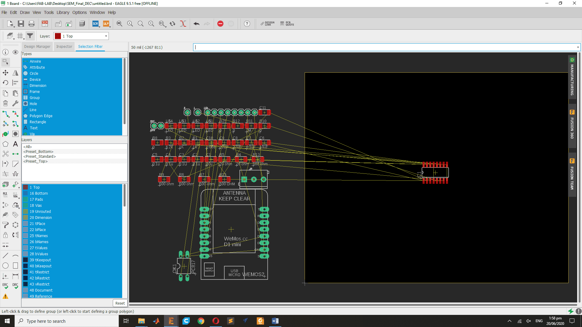
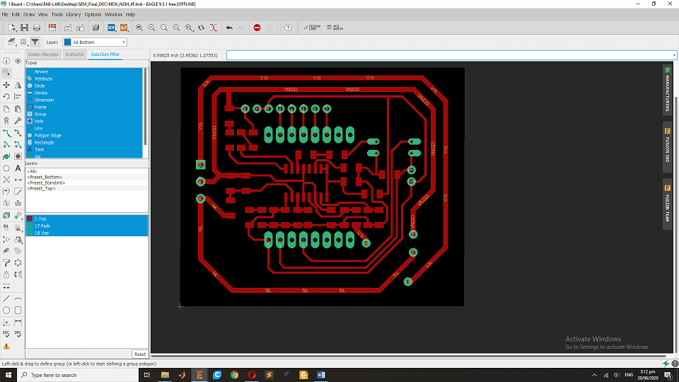
After the over all setting and adding the important library now eagle CAD is able to design the disaired design of Meter.So here is the ADE7757 energy meter IC in eagle CAD.Here.
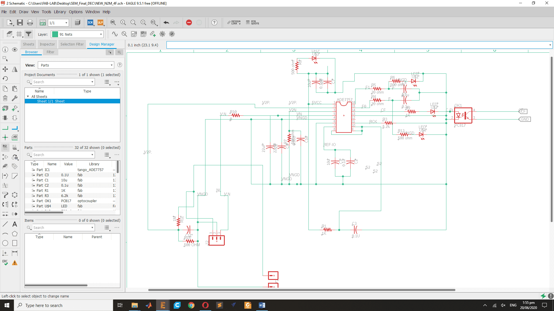
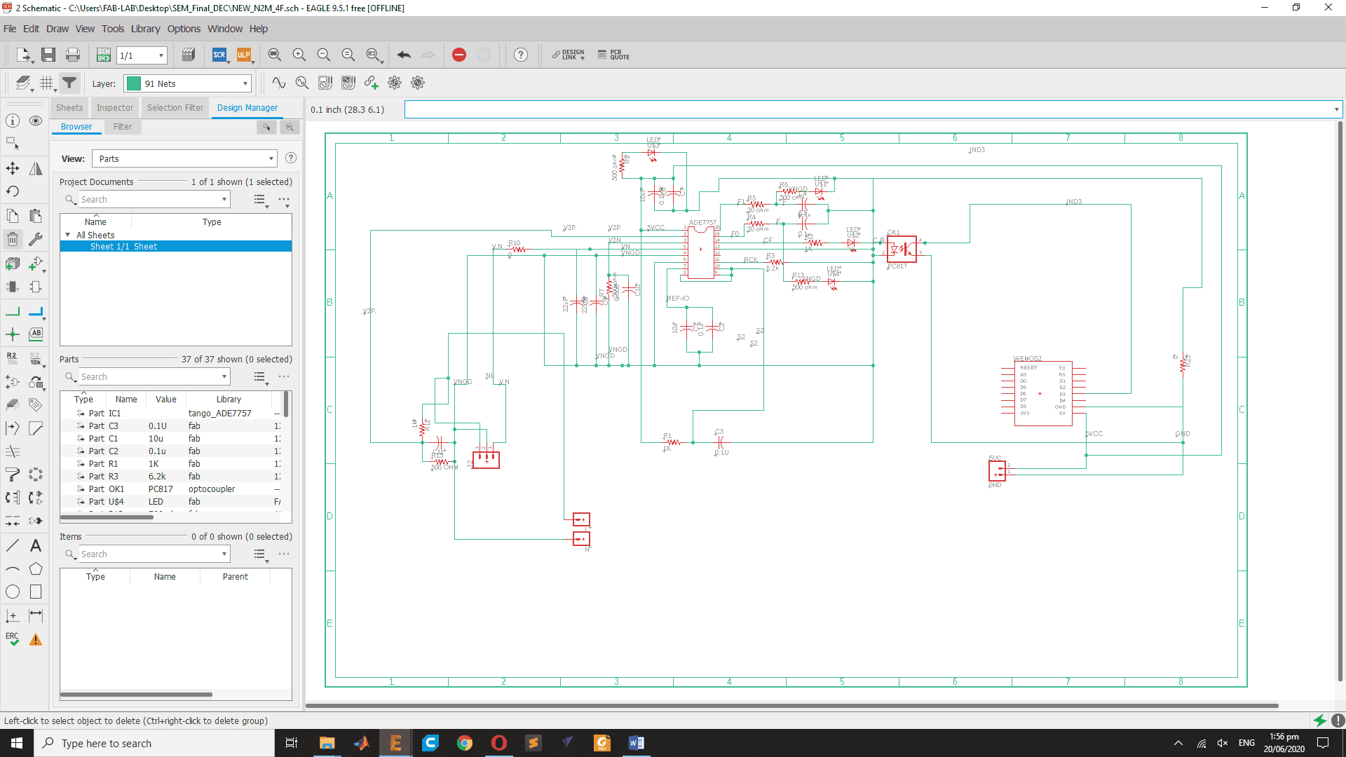
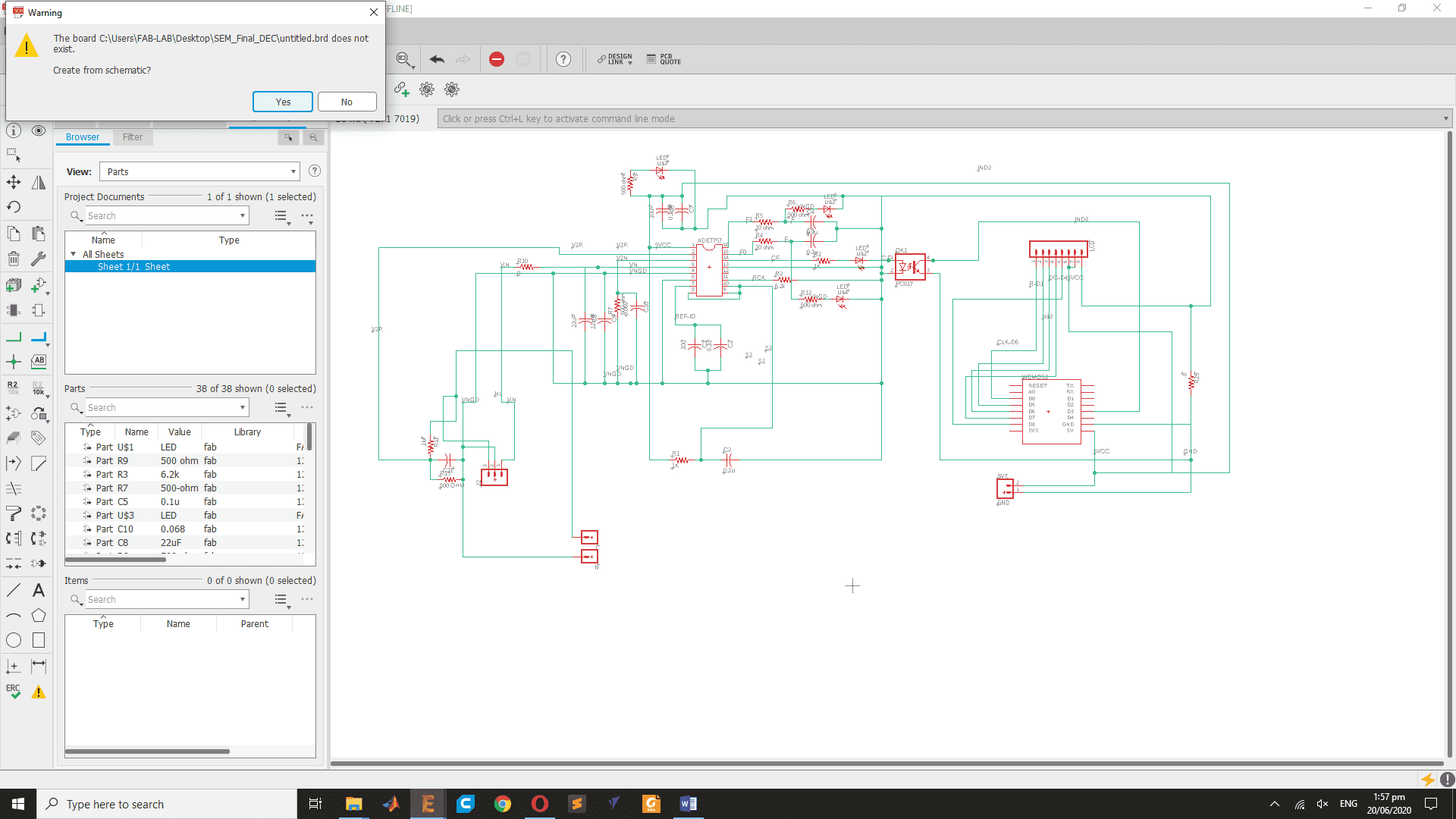
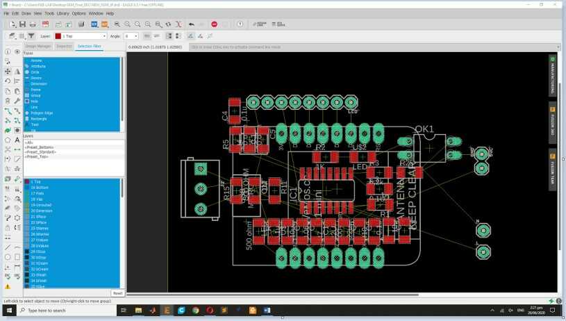
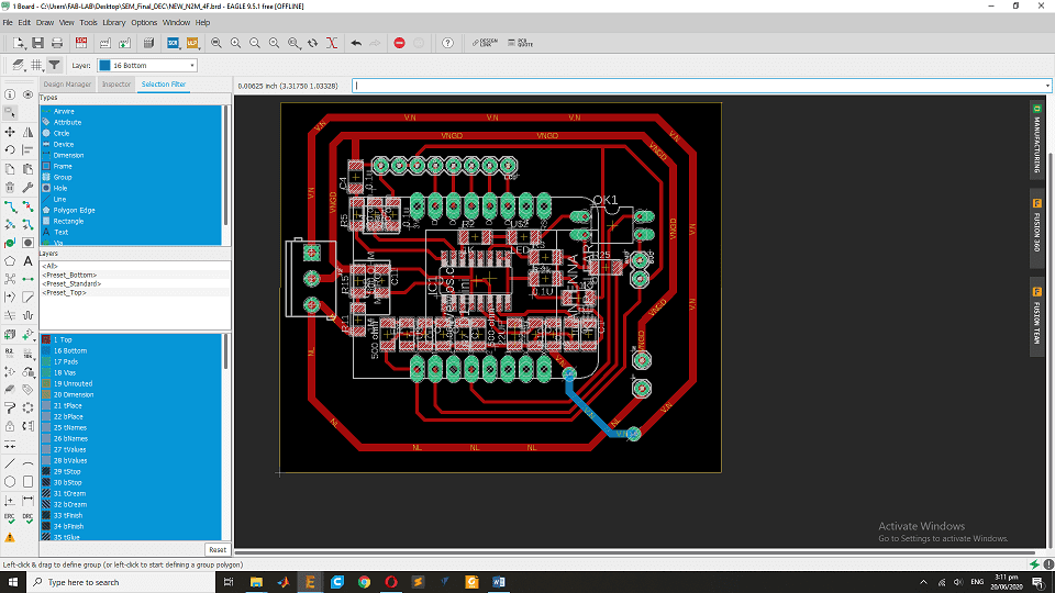
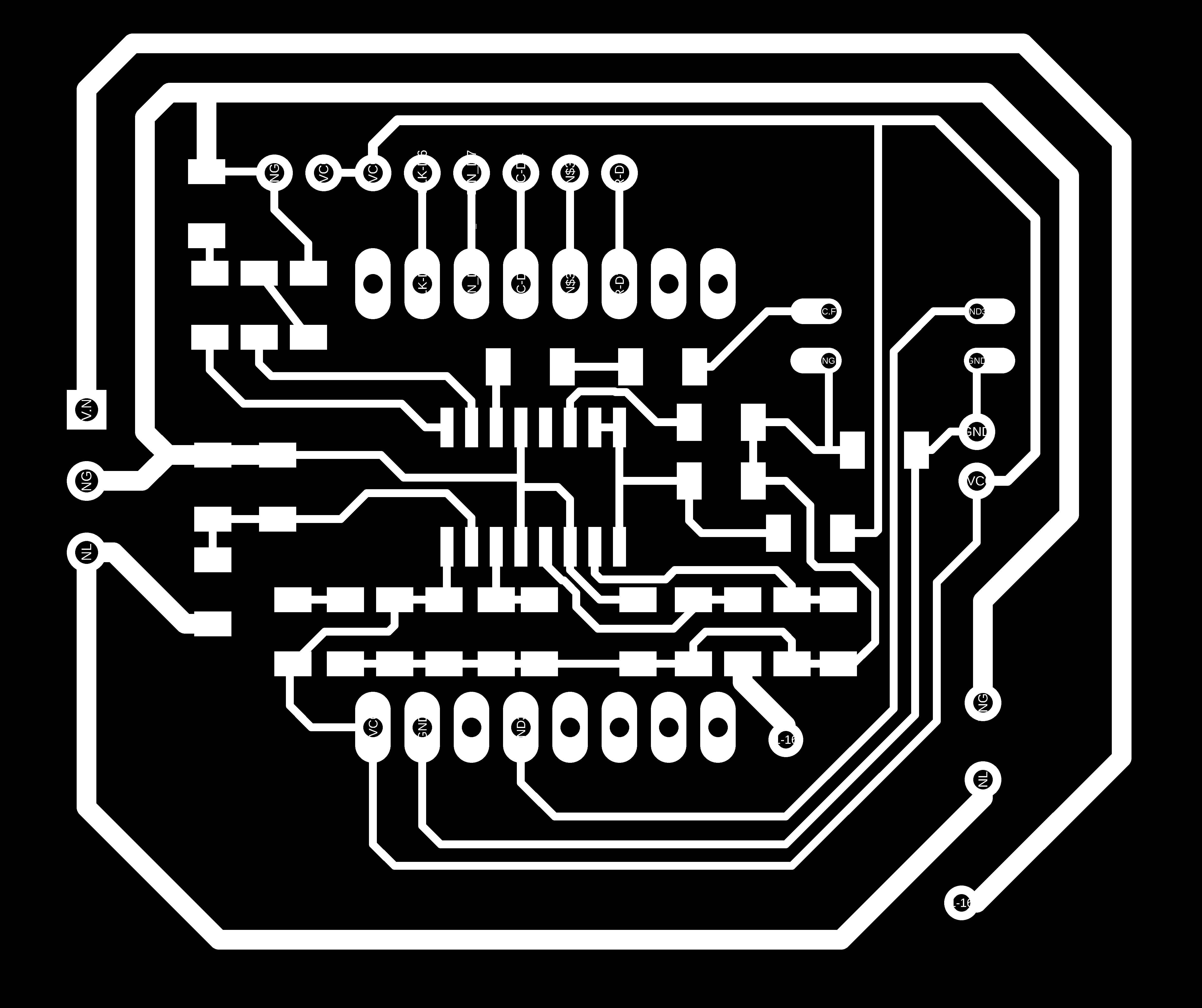
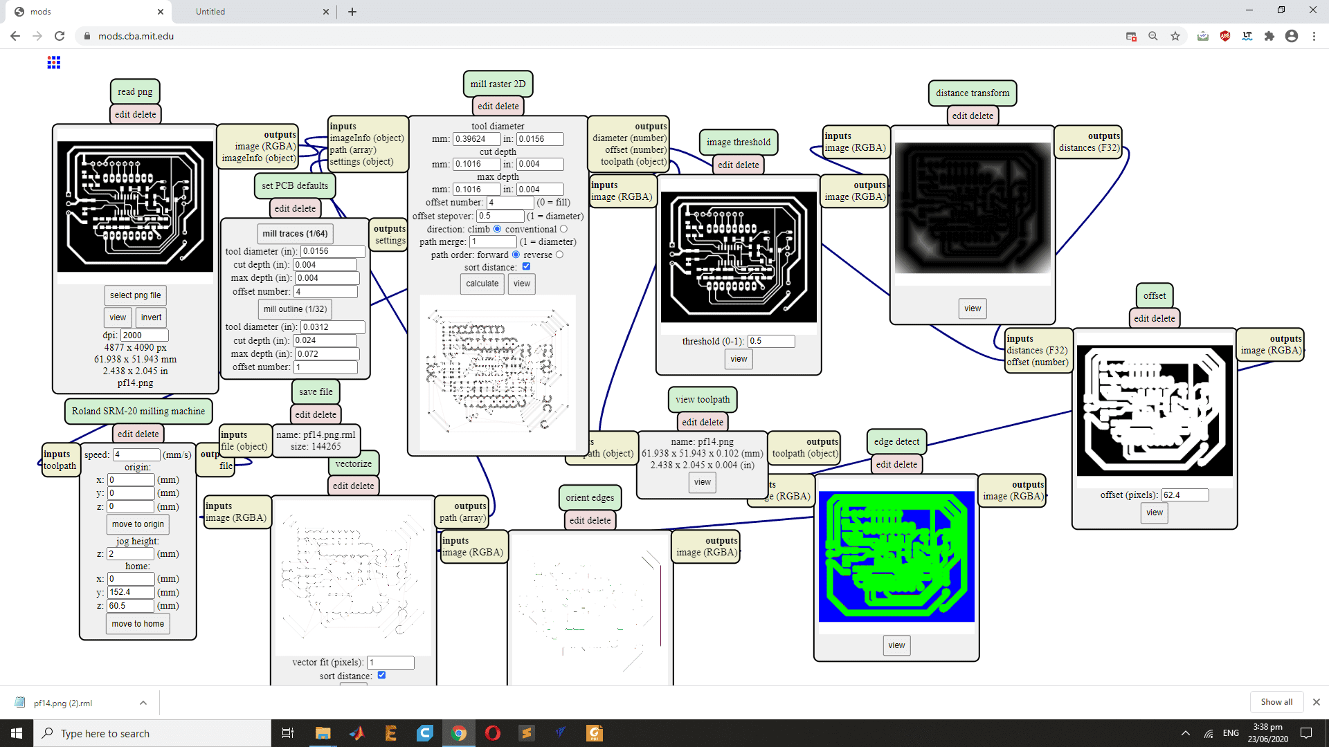
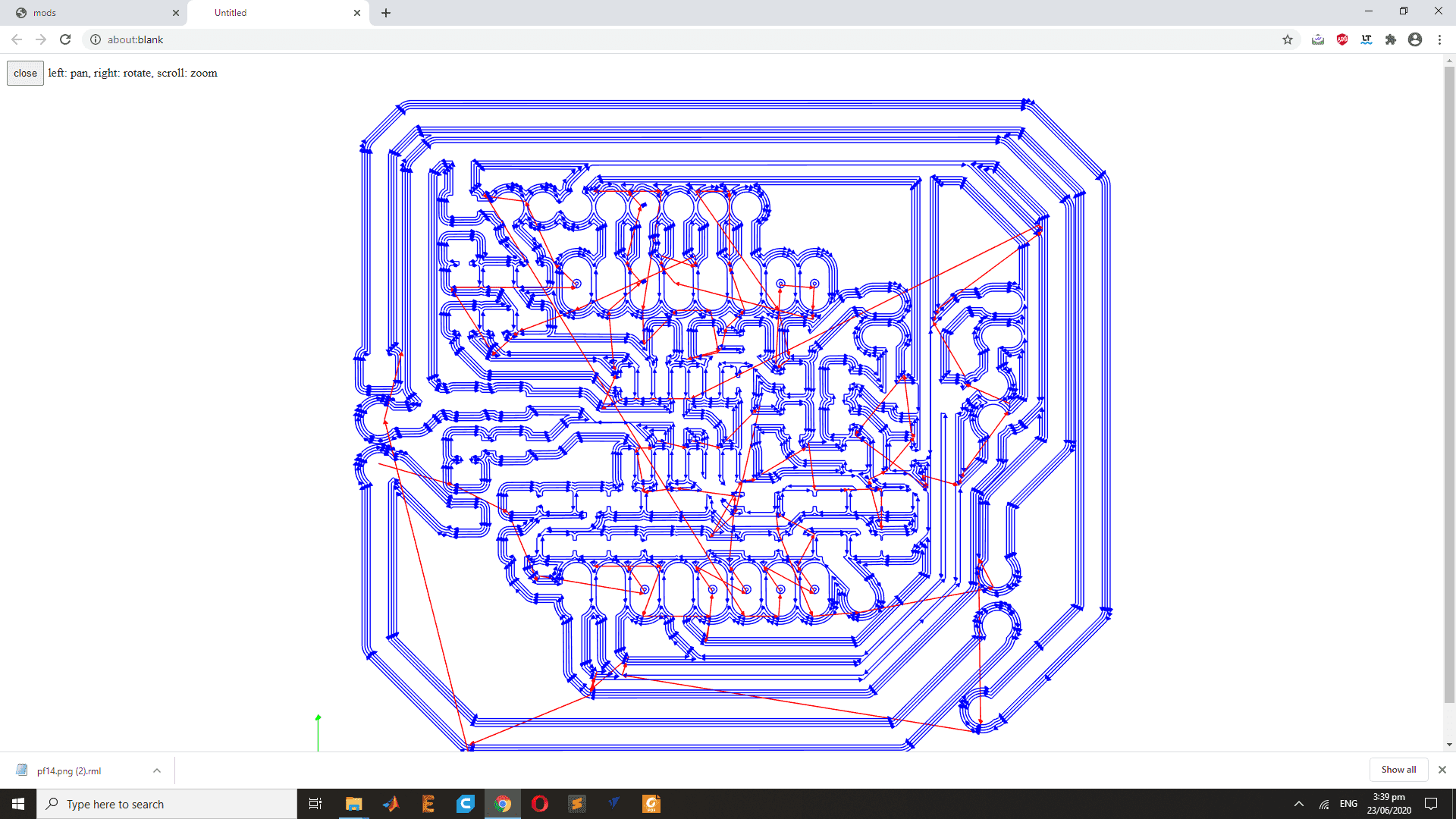
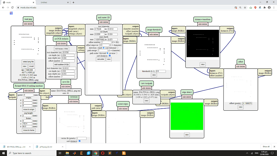
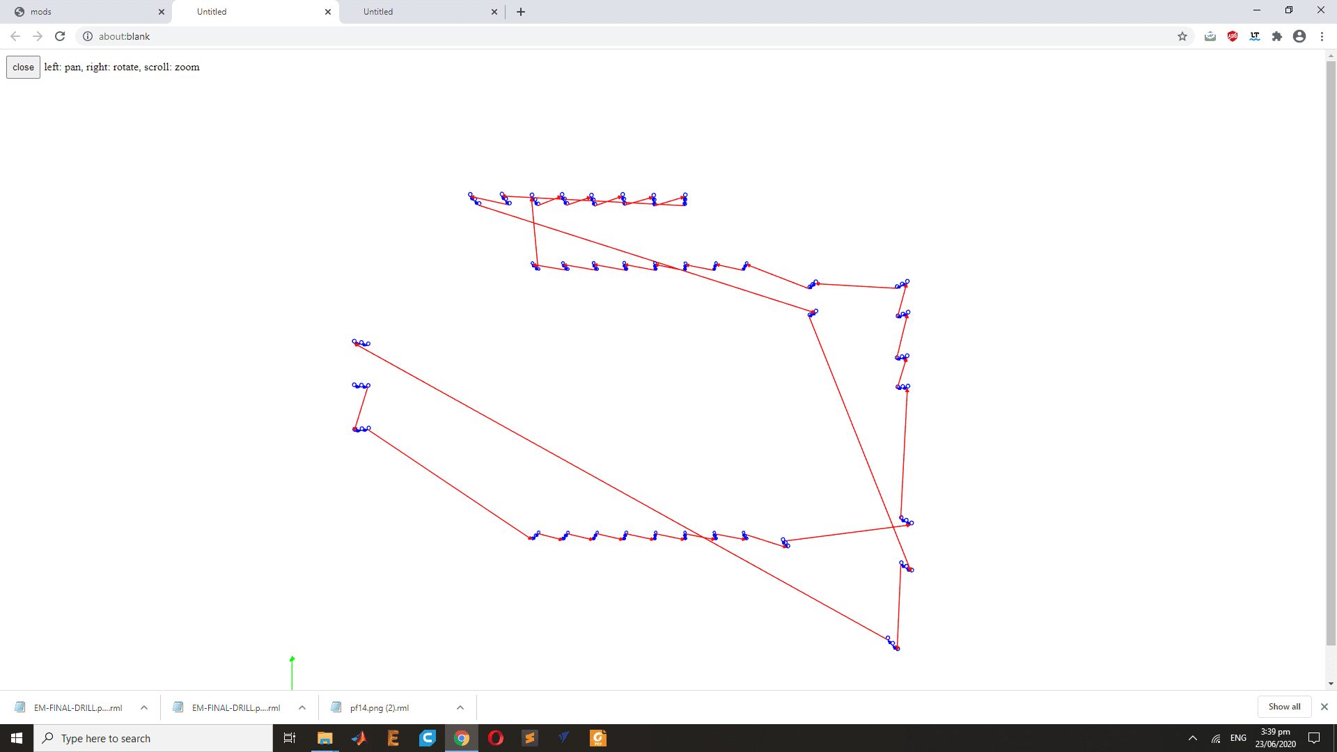
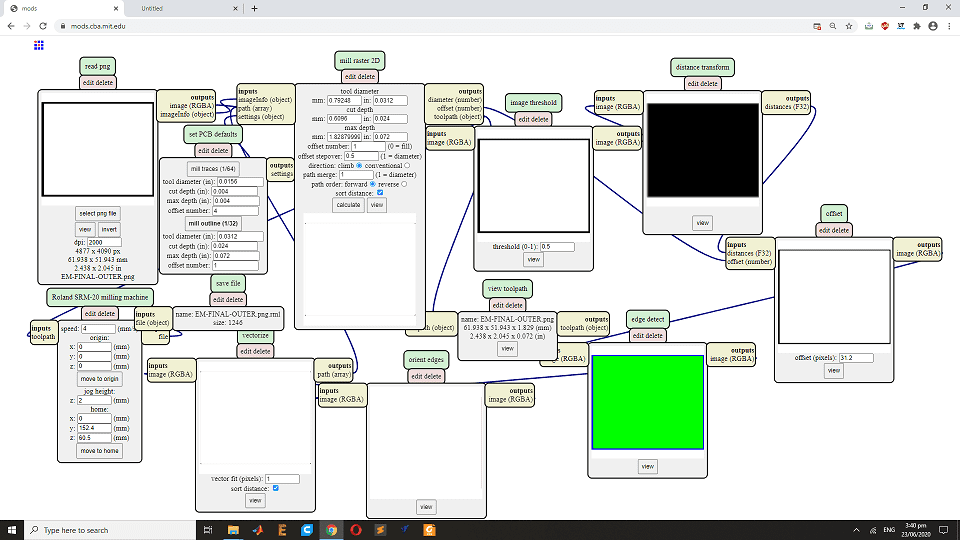
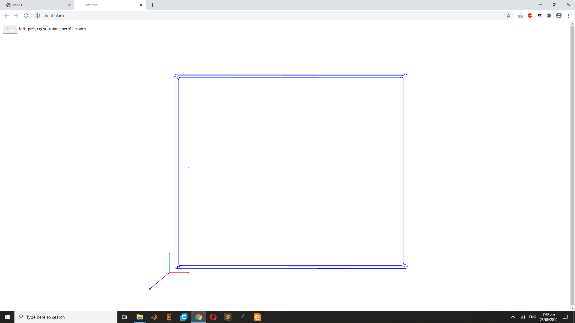
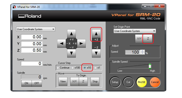
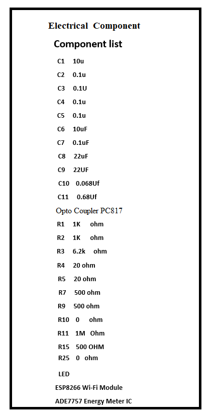
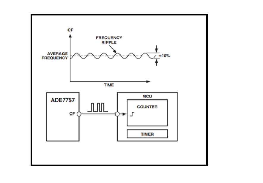
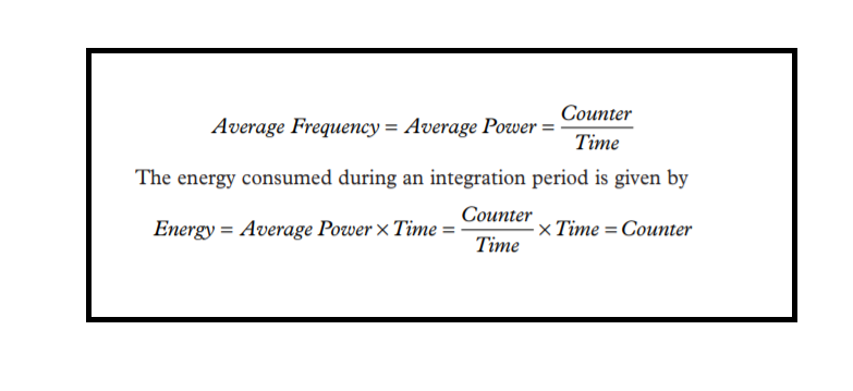
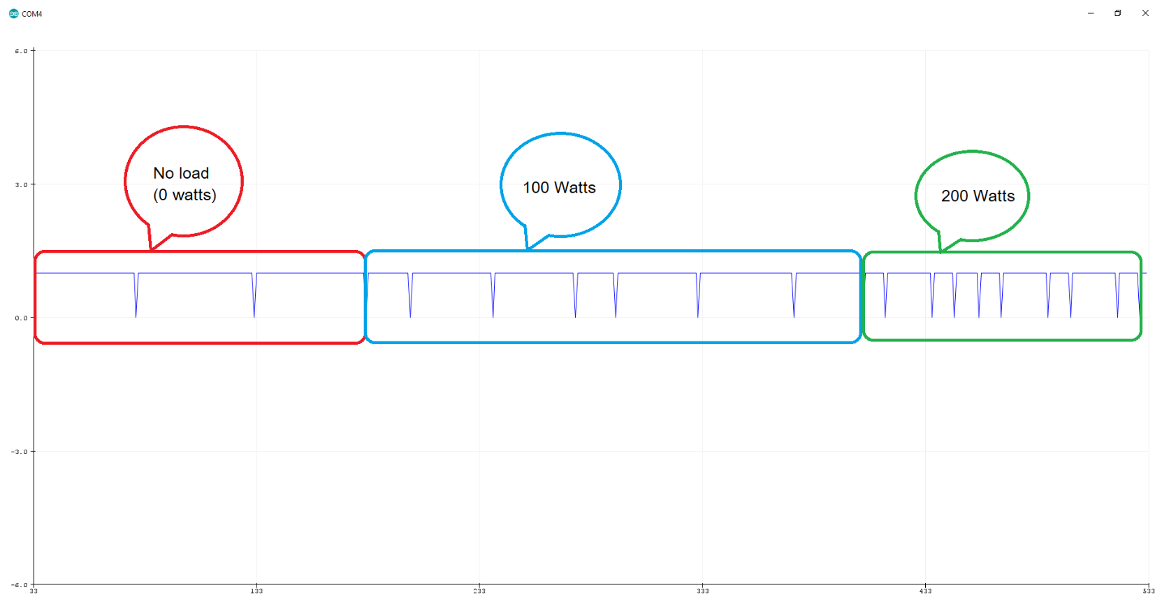
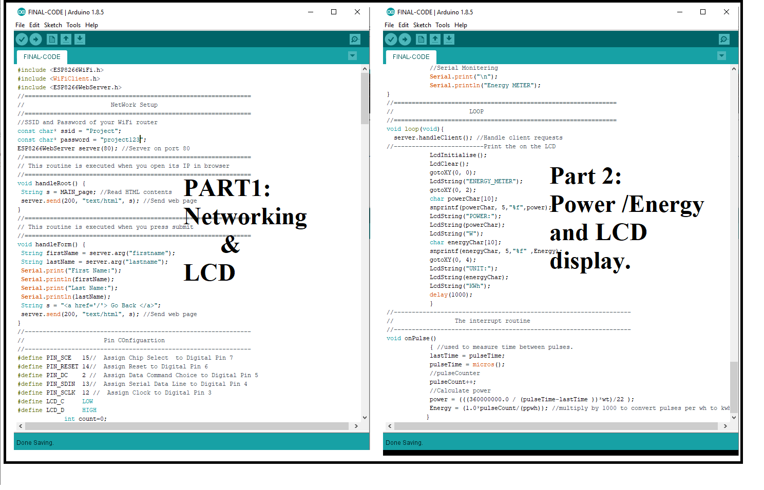
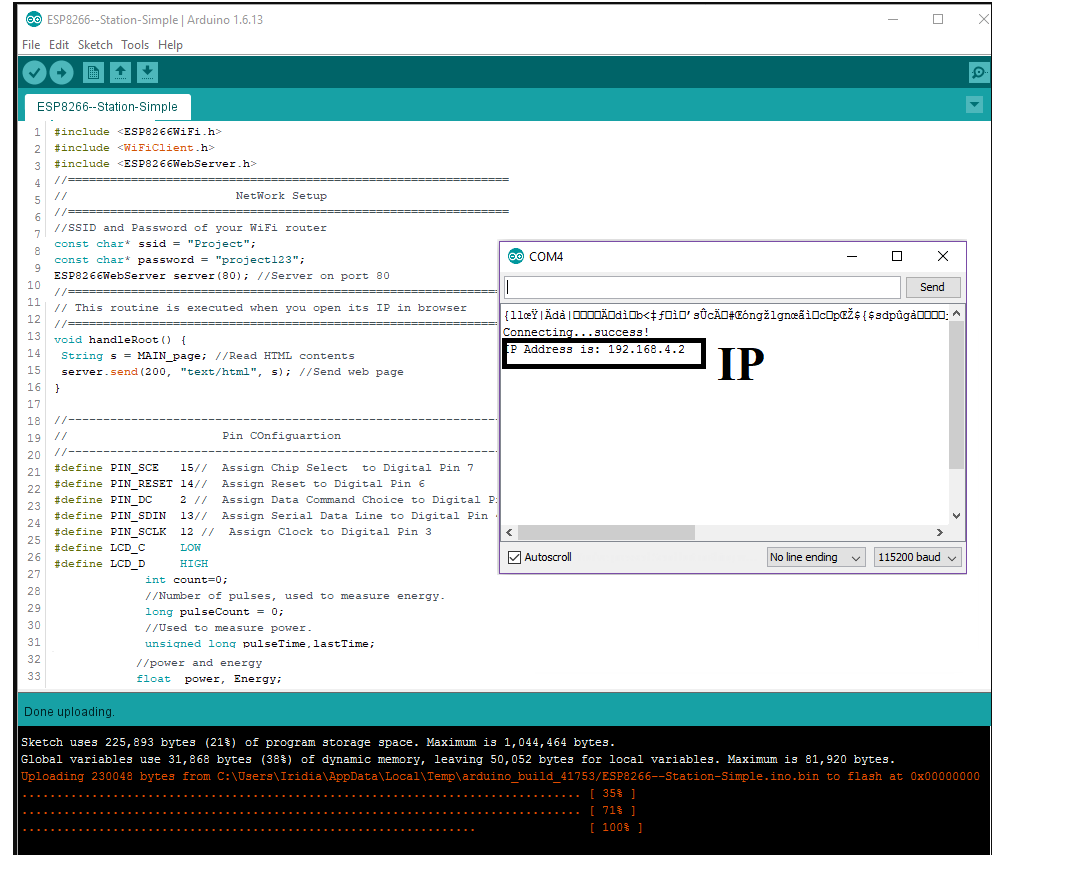
Now add all required components like a Resistor, Capacitor, Connectors, LEDs Shunt Resistor,optocoupler and other smd Components and connect the Connections by using wire.and this is the complete Breakout circuit of the Energy Meter. Now I will add microcontroller ESP 8266 Module for the communication.and connect the meter out putpin with the ESP8266 Digital pin D3 and Ground. After Connections of ESP-8266 with Energy meter and Now phase to connect the LCD.and it will change schematic to PCB board. After the Schematic design now phase to Placing and Routing to the PCB , So first placing and than Routing. Placing is the very important phase of the PCB design, after the completing the this now next phase is to rout the Circuit. Now this is the placing of the PCB board. Finale Look of the Energy Meter PCB. After the Routing and now I will generate the PNG for the rml code.so First set the layers Click to file goes to export images and then set the dot per inch (dpi) 2000,select the Mono chrome and click to save it. PNG file for the other Process For the generating the RML code we will use the MODs so HERE there are few Step reuired to run the Mods so here are thses Few parameters are required : First set the origion at axis on zeros. Second for milling of traces we use tools bit of 1/64. Now I will generate the rml code of the Trcae file. The result of the RML Toolpath . Now I will generate the rml code of Drill file. Now use the mods to Generate the tool path for the drill we use the toolbit of 1/32. The result of the RML Toolpath . Now I will generate the rml code of outer/boundary. Now use the mods to Generate the tool path for the drill we use the toolbit of 1/32. The result of the RML Toolpath . Milling is very senstive process for the PCB design,it gives the real shape to board, we we must work with care and select the required tools, for the trace we use the tool bit of (1/64) while for the drill and outer layer we will change the tool and (1/32). Hold the milling bit with one hand, loose the screw with another, and move the bit right on the surface of the board, and then keep the milling bit still so it can't move up when fastening the screw again. Remember to not tighten too much in order to avoid ruin the milling bit body surface. Now, reset the Z-axis to be zero by Set Origin Point and pressing Z. In order to let the milling bit turn on and speed up freely, move the Z-axis just a little bit up (around 5 steps with the x10) so, don’t leave the milling bit to the surface. Now, the machine preparation is done. While Milling the Board: When trace file finish the job then I have change the toolbit and use the 1/32 for the Drill and outer layer, After milling next pashse is to solder the PCB board. Before we are going for the solder the PCB first we know about the Bill of material list.Here is the list that we need to solder and up the Board. For the soldering we need solder Gun,Sodler material for soldering "lead-free rosin core solder" ,flux and Towser etc, and While soldering the Board : After Soldering this the result of the Board,Now looks. After the finishing Soldering part,Now phase to test the energy meter.So there are some instruction which we have to follow. Now last phase when all input section are connected and power up the board the fill will get the response on the PIN 14, 15, 16. Where these pins are called output pins. Hardware is working So the next step to program the device, for the programing I have divided my work in few steps, like LCD, Digital Input for the Energy and Power Calculation and in last cloud server or webpage. So, the first I will consider to stat work on the Power and Energy Calculation. Now for the Energy and Power calculation, we interface the pin 14 of out pin of IOC as a input for the Energy and power calculation , where Pin 14 is called CF calibration frequency, this pin of energy meter IC produce the Square pulse/ low Frequency that is easy to interface with the micro controller as a PCB Board design I have also connected with ESP-micro controller Circuit. The pulse output CF (calibration frequency) is intended for calibration purposes. The output pulse rate on CF can be up to 2048 times the pulse rate on F1 and F2. The lower the F1–4 frequency selected, the higher the CF scaling (except for the high frequency mode SCF = 0, S1 = S0 = 1). Table III shows how the two frequencies are related, depending on the states of the logic inputs S0, S1, and SCF. Due to its relatively high pulse rate, the frequency at CF logic output is proportional to the instantaneous real power. As with F1 and F2, CF is derived from the output of the low-pass filter after multiplication. However, because the output frequency is high, this real power information is accumulated over a much shorter time. Therefore, less averaging is carried out in the digital-to-frequency conversion. With much less averaging of the real power signal, the CF output is much more responsive to power fluctuations. In formula calculation first we calculate the Average Frequency is known as an Average power and its calculate with the help of the Counter and count the frequency or Square pulse which is comes from the Energy meter out pin to the micro controller digital pin. In this code I have just design the code of Power and Energy Calculation upload the code in Micro Controller and check the serial monitor for the Result and try to Fixed the values of Power and Energy and Here is the Code Snip in Arduino this Code is for the just Serial Monitoring and Plotter. Result on Serial Plotter and Serial Monitor using an Arduino: In this graph when no load then the pulse width is high , when the load is 100w then the pulse width is decrease small , in Particle I have load is 200w then the pulse width is small. this fact we will use to calculate the power and Energy. Now the Part is to design code for the Output LCD, Click, I have define LCD Pins and Upload it LCD Show the Display Power and Energy in KWh ,In the final Code will be combine Code. In this part First I will connect try to connect the Wi-Fi code and then design the cloud GUI, So lets start with the Wi-Fi code, we need to set ISSD “Project” and wi-fi Password”project123”.and uplad it after few second I will connect and give us this IP result. After the upload the combine code of LCD display ,Power and Energy Calculation and WiFi with Webpage Based GUI code.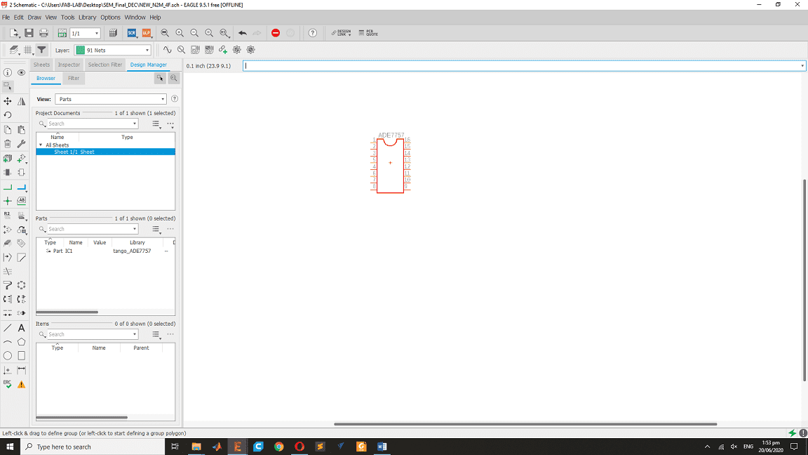

RML code


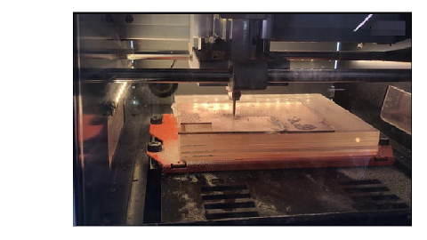
Milling Process
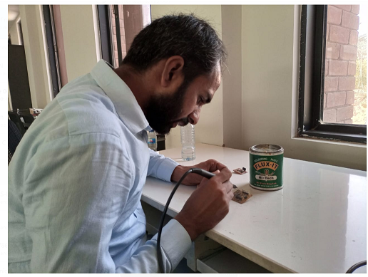
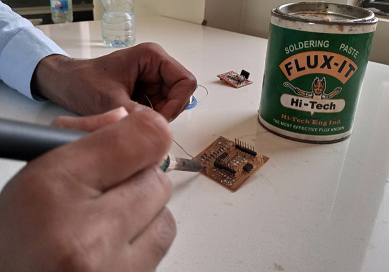
Soldering
Energy Meter Testing Process:
Programing
float count=0;
//Number of pulses, used to measure energy.
long pulseCount = 0;
//Used to measure power.
unsigned long pulseTime,lastTime;
//power and energy
float power, Energy;
float wt=1.16 ;// Factor: 1.18
//Number of pulses per wh - found or set on the meter.
float ppwh = 1000; //1000 pulses/kwh = 1 pulse per wh
void setup(){
Serial.begin(115200); // KWH interrupt attached to IRQ 1 = pin3
attachInterrupt(0,onPulse, FALLING);
void loop() {
float onPulse:
}
void onPulse()
{ //used to measure time between pulses.
lastTime = pulseTime;
pulseTime = micros();
//pulseCounter
pulseCount++;
//Calculate power
power = (((3600000000.0 / (pulseTime-lastTime ))*wt)/22 );
Energy = (1.0*pulseCount/(ppwh)); //multiply by 1000 to convert pulses per wh to kwh
Serial.println("\n");
Serial.println(power,2);
Serial.println("W");
Serial.println(Energy,4);
Serial.println("Wh");
}
}
#include ESP8266WiFi.h
#include WiFiClient.h
#include ESP8266WebServer.h
//===============================================================
// NetWork Setup
//===============================================================
//SSID and Password of your WiFi router
const char* ssid = "Project";
const char* password = "project123";
ESP8266WebServer server(80); //Server on port 80
//===============================================================
// This routine is executed when you open its IP in browser
//===============================================================
void handleRoot() {
String s = MAIN_page; //Read HTML contents
server.send(200, "text/html", s); //Send web page
}
//---------------------------------------------------------------
// Pin COnfiguartion
//---------------------------------------------------------------
#define PIN_SCE 15;// Assign Chip Select to Digital Pin 7
#define PIN_RESET 14; // Assign Reset to Digital Pin 6
#define PIN_DC 2; // Assign Data Command Choice to Digital Pin 5
#define PIN_SDIN 13;// Assign Serial Data Line to Digital Pin 4
#define PIN_SCLK 12; // Assign Clock to Digital Pin 3
#define LCD_C LOW
#define LCD_D HIGH
int count=0; //Number of pulses, used to measure energy.
long pulseCount = 0; //Used to measure power.
unsigned long pulseTime,lastTime; //power and energy
float power, Energy;
float wt=1.16 ;// Factor: 1.18 //Number of pulses per wh - found or set on the meter.
int ppwh = 1000; //1000 pulses/kwh = 1 pulse per wh
//---------------------------------------------------------------------
// LCD Setup
//---------------------------------------------------------------------
#define TFT_CS 16
#define TFT_RST 8
#define TFT_MISO 09
#define TFT_MOSI 10
#define TFT_CLK 1
//===============================================================
// This routine is executed when you press submit
//===============================================================
void handleForm() {
String firstName = server.arg("firstname");
String lastName = server.arg("lastname");
Serial.print("First Name:");
Serial.println(firstName);
Serial.print("Last Name:");
Serial.println(lastName);
String s = " Go Back ";
server.send(200, "text/html", s); //Send web page
}
void handleRoot(){
server.sendHeader("Location", "/index.html",true); //Redirect to our html web page
server.send(302, "text/plane","");
}
//==============================================================
// SETUP
//==============================================================
void setup(void){
Serial.begin(9600);
WiFi.begin(ssid, password); //Connect to your WiFi router
Serial.println("");// Wait for connection
while (WiFi.status() != WL_CONNECTED) {
delay(500);
Serial.print(".");
}//If connection successful show IP address in serial monitor
Serial.println("");
Serial.print("Connected to ");
Serial.println("WiFi");
Serial.print("IP address: ");
Serial.println(WiFi.localIP());
//-------------------------------------------
//IP address assigned to your ESP
server.on("/", handleRoot); //Which routine to handle at root location
server.on("/action_page", handleForm); //form action is handled here
server.begin(); //Start server
Serial.println("HTTP server started");
// KWH interrupt attached to IRQ 1 = pin3
attachInterrupt(0, onPulse, FALLING);
//Serial Monitering
Serial.print("\n");
Serial.println("Energy METER");
}
//==============================================================
// LOOP
//==============================================================
void loop(void){
server.handleClient(); //Handle client requests
//-------------------------Print the on the LCD
tft.begin();
LcdInitialise();
LcdClear();
gotoXY(0, 0);
LcdString("ENERGY_METER");
gotoXY(0, 2);
char powerChar[10];
snprintf(powerChar, 5,"%f",power);
LcdString("POWER:");
LcdString(powerChar);
LcdString("W");
char energyChar[10];
snprintf(energyChar, 5,"%f" ,Energy);
gotoXY(0, 4);
LcdString("UNIT:");
LcdString(energyChar);
LcdString("Wh");
delay(1000);
}
//------------------------------------------------------------------
// The interrupt routine
//------------------------------------------------------------------
void onPulse()
{ //used to measure time between pulses.
lastTime = pulseTime;
pulseTime = micros();
//pulseCounter
pulseCount++;
//Calculate power
power = (((360000000.0 / (pulseTime-lastTime ))*wt)/22 );
Energy = (1.0*pulseCount/(ppwh)); //multiply by 1000 to convert pulses per wh to kwh
}
After that I have design the GUI for Webpage using the C++/ HTML langauge using Arduino and its look like that.
// This code is design for the webpage .
// in this code we have use design for the Power and Energy
// this page will take data in after every one second
!DOCTYPE html
html
head
script src="\jquery.min.js">
script src="\d3-gauge.js">
link rel="stylesheet" href="\style.css"
/head
body
script
setInterval(function() {
//Gets ADC value at every one second
//ADC is file that is store tha used In Arduino ide Main final code.
GetADC();
}, 1000);
function GetADC() {
var xhttp = new XMLHttpRequest();
var adc=0;
xhttp.onreadystatechange = function() {
if (this.readyState == 4 && this.status == 200) {
adc = Number(this.responseText);
gauges.forEach(function (gauge) {
console.log(adc)
gauge.write(adc);
});
}
};
xhttp.open("GET", "/getADC", false);
xhttp.send();
}
var gauges = [];
var small = {
size : 100
, min : 0
, max : 1000
, transitionDuration : 100
, label : 'label.text'
, minorTicks : 4
, majorTicks : 5
, needleWidthRatio : 1
, needleContainerRadiusRatio : 0.7
, zones: [
{ clazz: 'black', from: 0.73, to: 0.9 }
, { clazz: 'white', from: 0.9, to: 1.0 }
]
};
function createGauge (opts) {
var el = document.createElement('div');
el.setAttribute('class', 'gauge-container');
document.body.appendChild(el);
var g = d3Gauge(el, opts);
g.currentValue = g._range / 2;
gauges.push(g);
}
createGauge({ clazz: 'simple', label: 'Power (watts)' });
createGauge({ clazz: 'simple', label: 'Energy (Wh)' });
/script
/body
/html
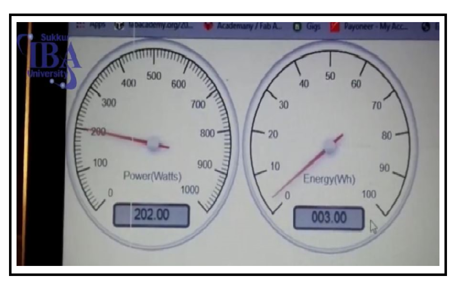
This is the GUI of Energy Meter that is receive the data from the Energy meter board wireless by ESP Micro controller.
3D Design and Printing
Now the last step is to design the Energy meter Casing, it's very hard time for me to design the CAD design nonetheless I have design the CAD in solid work,as I have planed to design the Casing looks as I have mentioned in week Principles and Practices as I have also use the CAD in Week CNC Make some thing big Week Composite Wildcard and Week of Molding and Casting so lets Start the CAD design.
First I have open the Solidwork and set the plan and draw the Sketch and Design the Front/Top View of the Energy Meter in top view I have add the output whole and LCD display View.
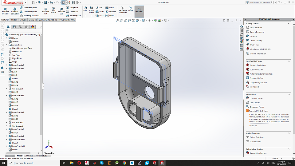
This is Top View of the Casing.
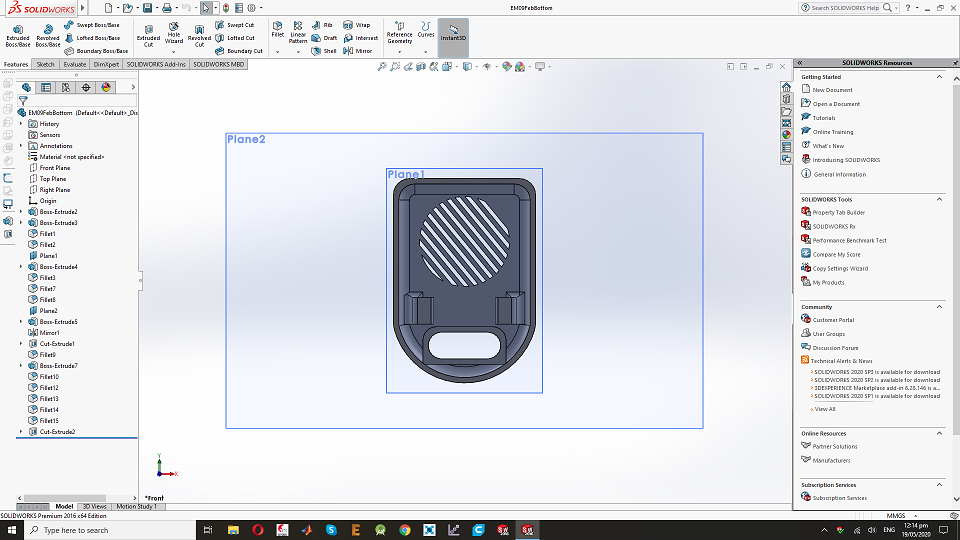
After the front design I have design the back view of the Energy meter and put Two wholes for the Input AC 220V.
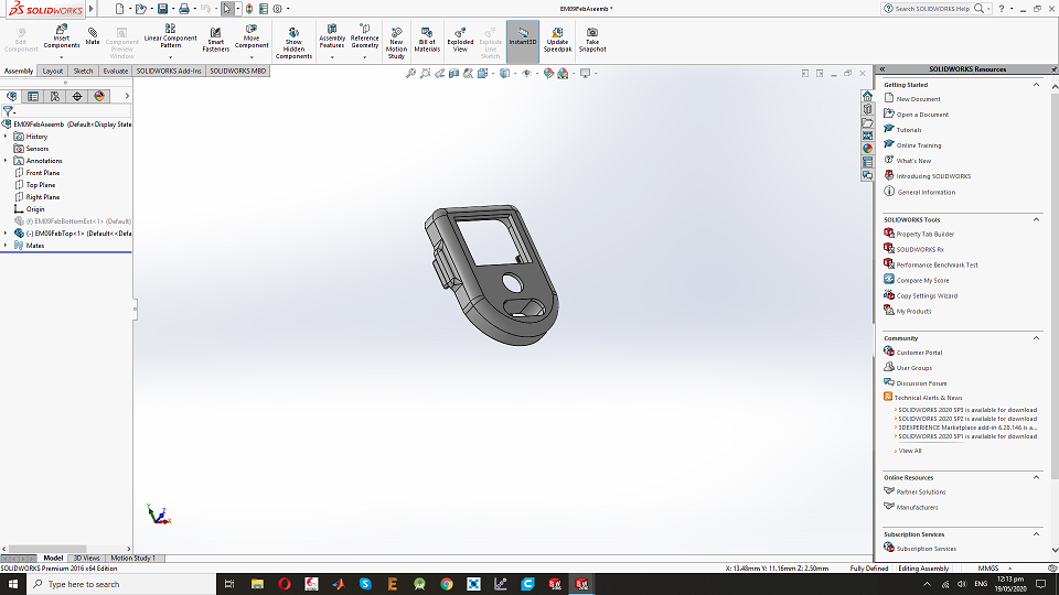
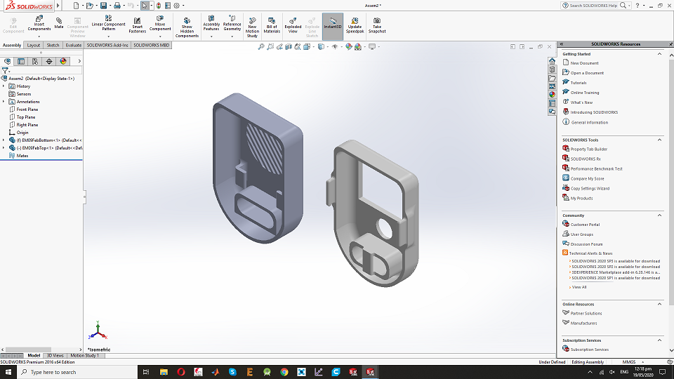
Now I have mate them in one plane.
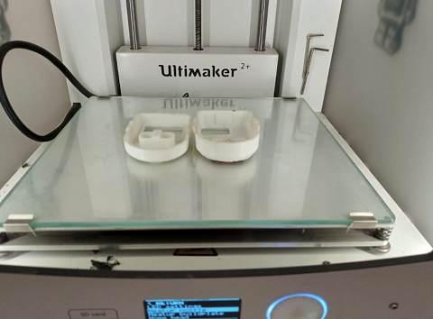
After the CAD design now phase is to Print it,I have save the in .stl from the solid work , for the Printing I am using the ultimaker S3 Click on User maunal. this is the printing file.
This is the view of the 3D printing after the printing.
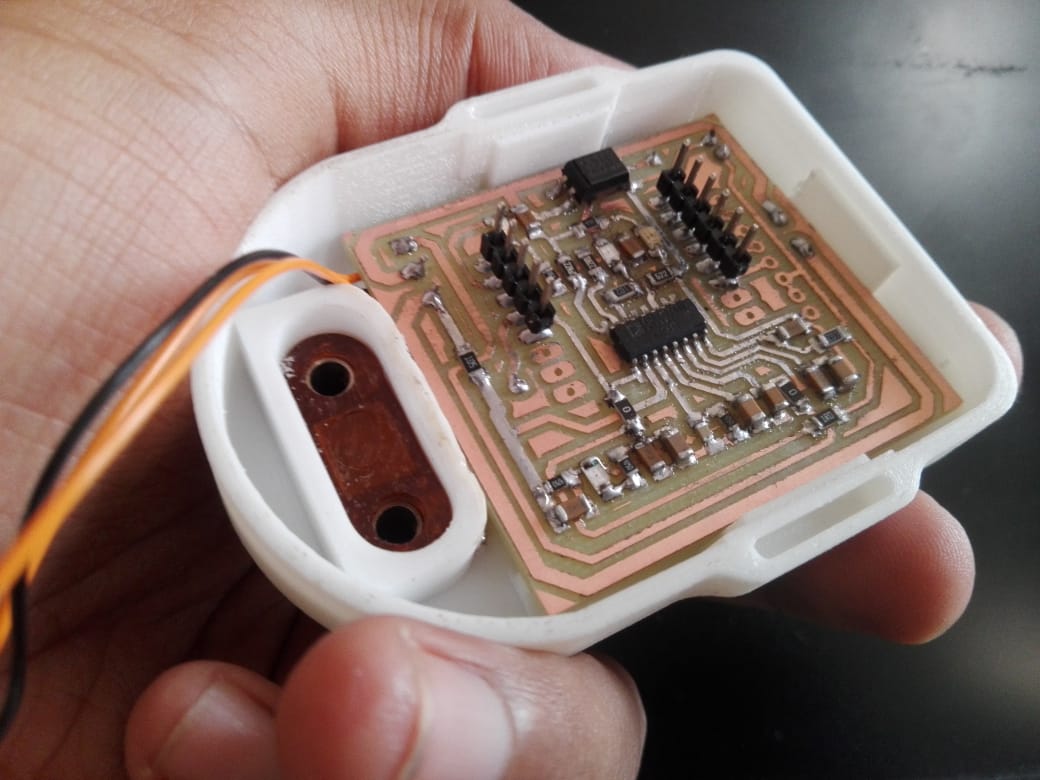
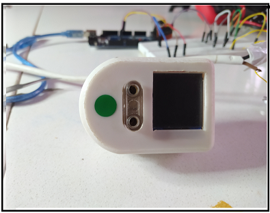
Final assembling of the Devices : " Energy Meter ".
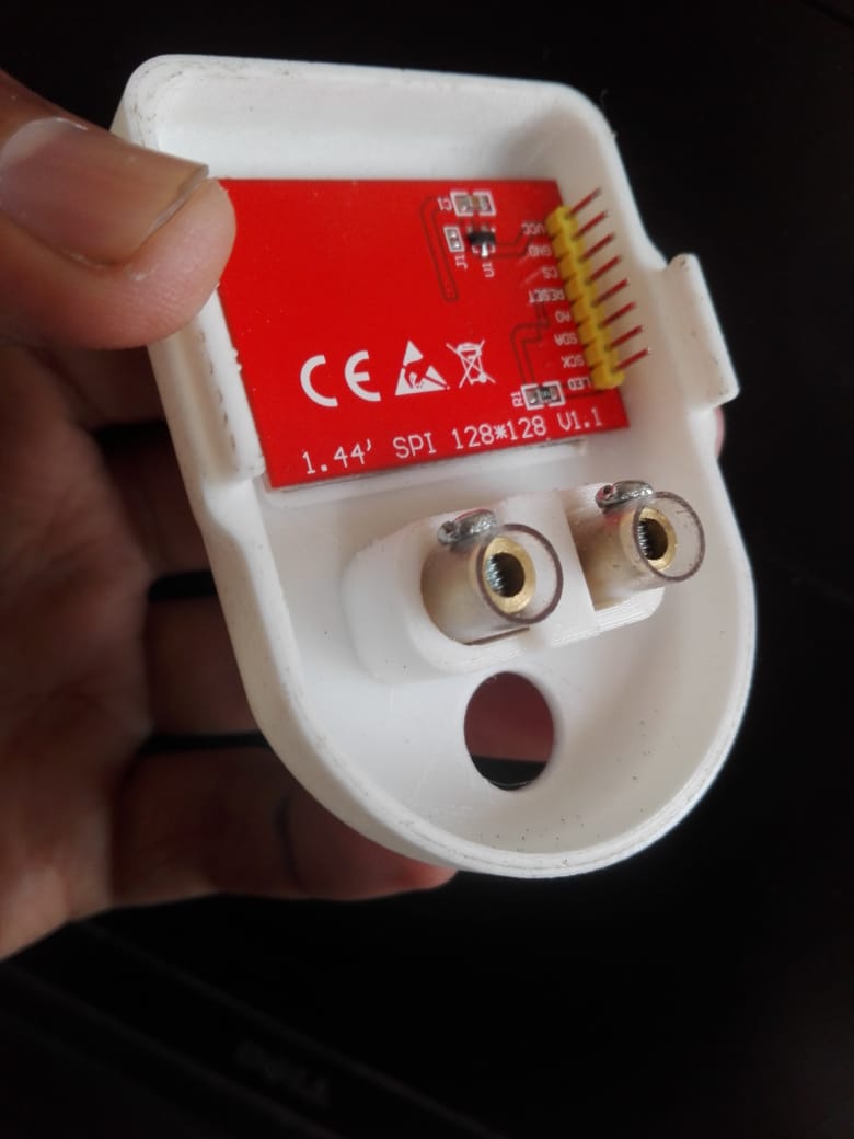
Break out board circuit assembly
In final Back of the Energy Meter.
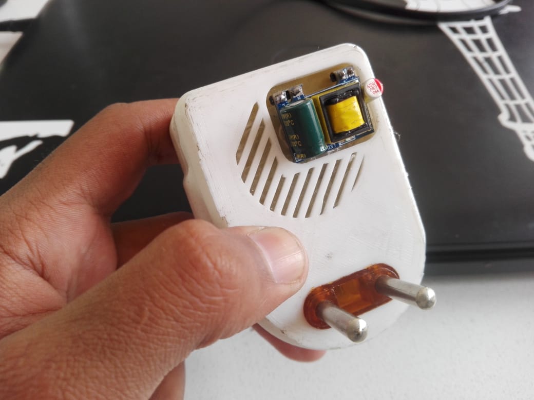
Final Look of the Energy Meter :
Bill of material that required to design the Energy meter . Principles and Practices. as well as week Applications and implications
Conclusion
My final project is to design the Smart Energy meter,I have divided my project in parts , first I have design the PCB board and Milling, Second part is testing and programing and third one is the 3D design and Printing.So First I have design the PCB board and mill it after that i have solder the Board,after the soldering I have test my board with 100w nad 200w load.In programing I have first work on the pulse detection code than LCD interface after WiFi the Code and combine it and upload.last phase is to design the 3D casing and printing .in final I have assembled the devices.
Acknowledgment:
First and foremost "Syukur Alhamdulillah" to Allah SWT ,the Most Gracious and Most Merciful for ensuring myself to be healthy to carry out my study and to complete my final project.
Secondly, I would like to express my warmest gratitude to my supportive supervisor, Dr. Professor, Neil Gershenfeld,Dr Muhammad Asim ,Engr. Sohail Ahmed , Fab lab Co-coordinator Engr. Fida Hussain Memon , My FAB Instructors Engr. Noor Ahmed Raza , Engr. Rasheed Ahemd Qazi , who has provided support and Guidance for This Digital Fabrication Diploma.
I would like to thank my loved ones, who have supported me throughout entire process, both by keeping me harmonious and helping me putting pieces together. I will be grateful forever for your love and Kind Support.

This work is licensed under a Creative Commons Attribution-NonCommercial-ShareAlike 4.0 International License