Group Assignment
Design a machine that includes mechanism + actuation + automation.
Build the mechanical parts and operate it manually.
Actuate and automate your machine.
Document the group project.
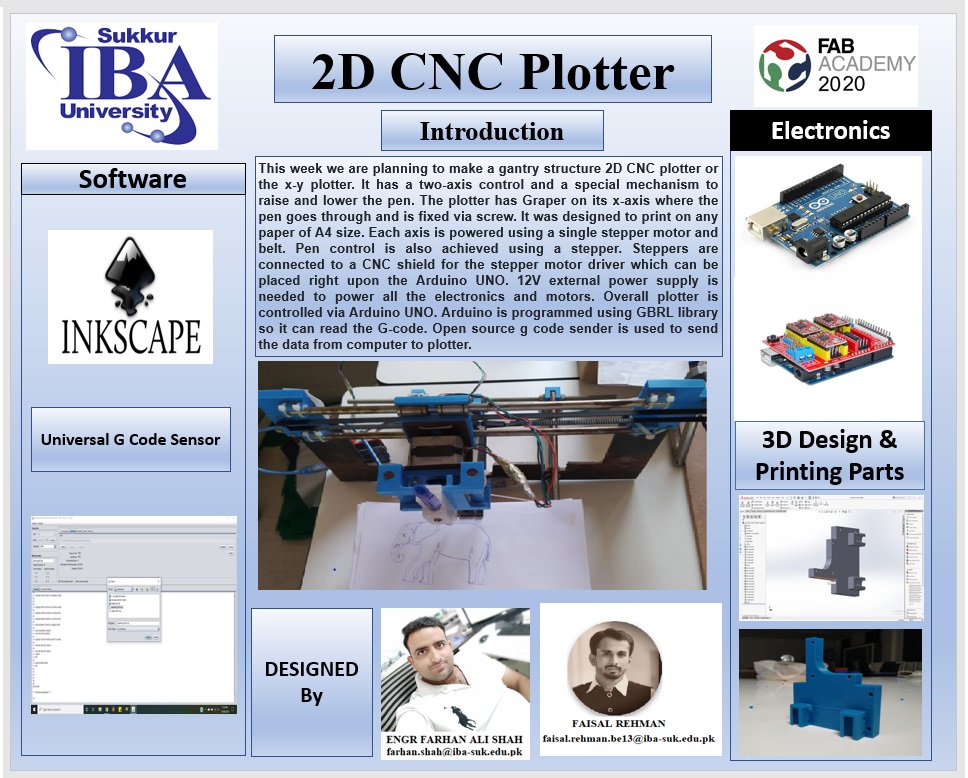
2D CNC Plotter
This week we are planning to make a gantry structure 2D CNC plotter or the x-y plotter. It has a two axis control and a special mechanism to raise and lower the pen. The plotter has graper on its x-axis where the pen goes through and is fixed via screw. It was designed to print on any paper of A4 size. Each axis is powered using a single stepper motor and belt. Pen control is also achieved using a stepper. Steppers are connected to a CNC shield for the stepper motor driver which can be placed right upon the arduino UNO. 12V external power supply is needed to power all the electronics and motors. Overall plotter is controlled via arduino UNO. Arduino is programmed using GBRL library so it can read the G-code. Open source g code sender is used to send the data from computer to plotter.
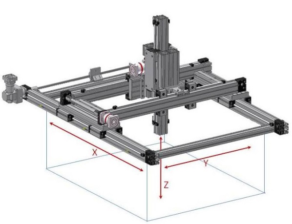
Gantry structure
A gantry is defined as “any of various spanning frameworks, as a bridge-like portion of certain cranes.” In other words, it is a structure that bridges over an area. Like gantry cranes, the word is often used to refer to a structure that moves on wheels, often riding on a set of parallel rails. For more example on gentry CLICK.
Model of our plotter
The present model is the first prototype created for gantry structure CNC plotter with steel rode and 3D parts. There are still several problems to solve, mainly of precision, and on the other hand there are also many ideas that can be made from this model. Our model consist of 3D printed parts along with metal rode and threaded rods. 3D printed parts are used to join metal rods and also used to fix the motorr. End factor is completly made of 3D printed parts.
3D designing
First of all we have designed the 3D parts for the 2d CNC Plotter by using the Solid Work and Print them by using the 3D Printer Ultimaker 2+.
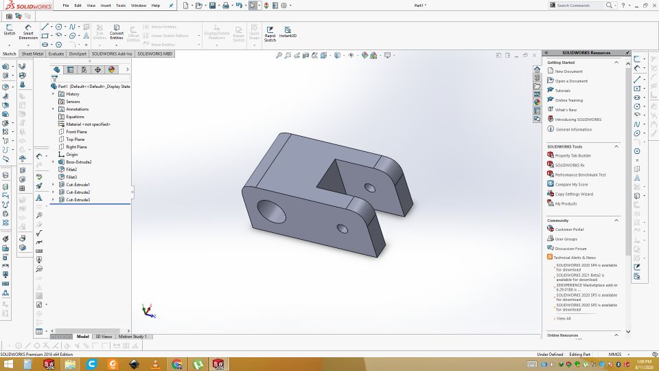
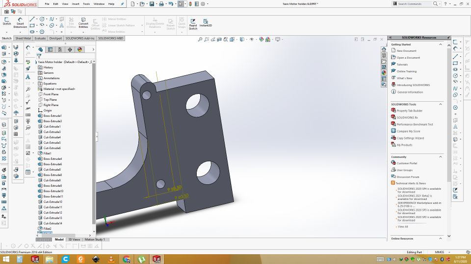
Corner parts of structure
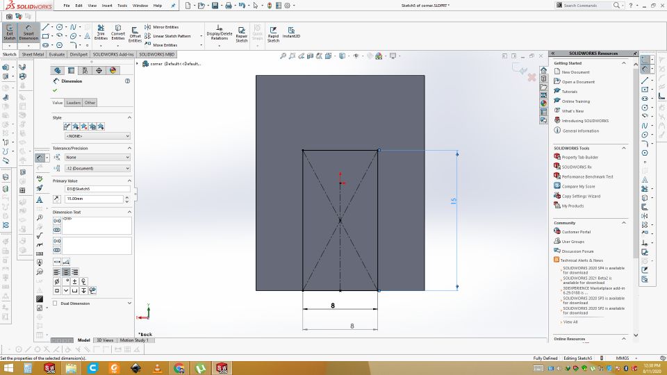
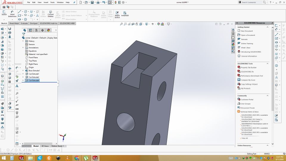
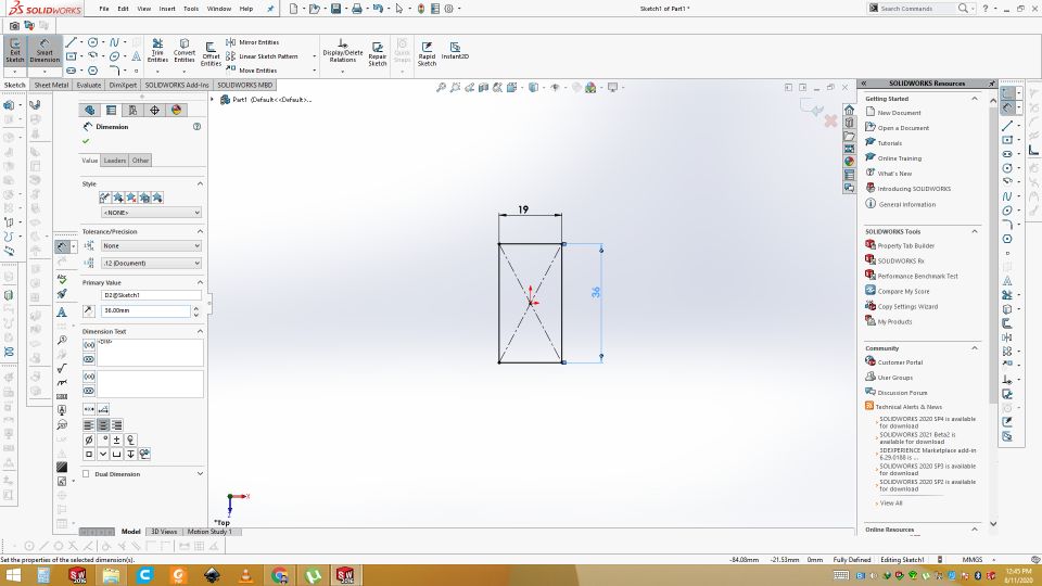
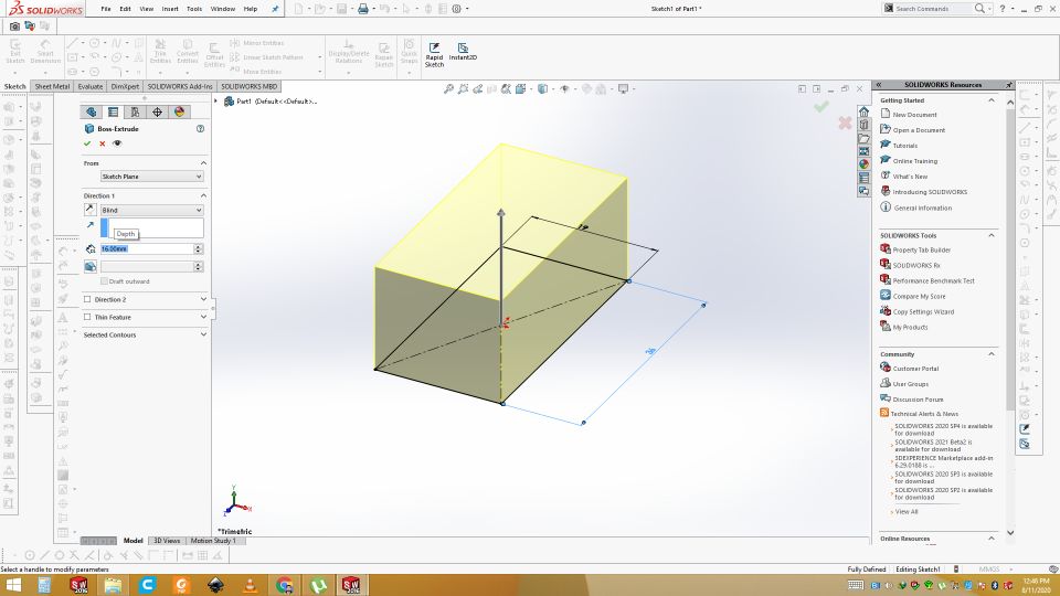
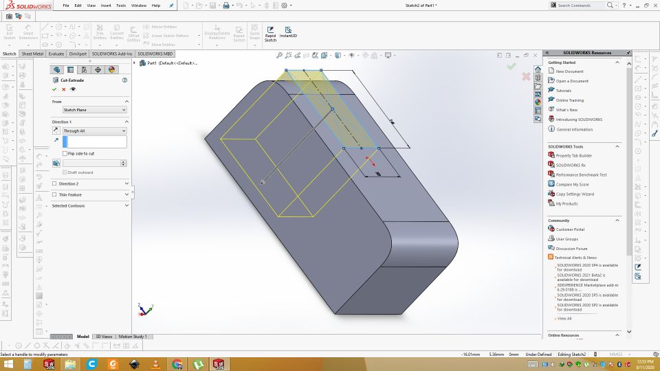
Open the solidworks. Frist, I have designed the Corners 3d parts on which rods will be fixed. We need 4 peice of this part. Frist of all the draw the shape then Extrude it. Draw the throgh hole on center for the corner fixing. Through hole both side for y axis fixing.
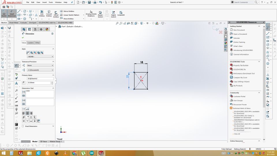
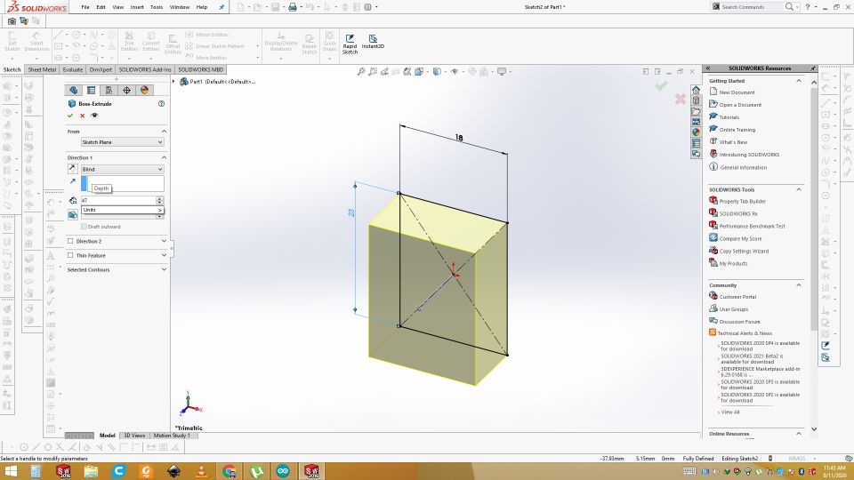
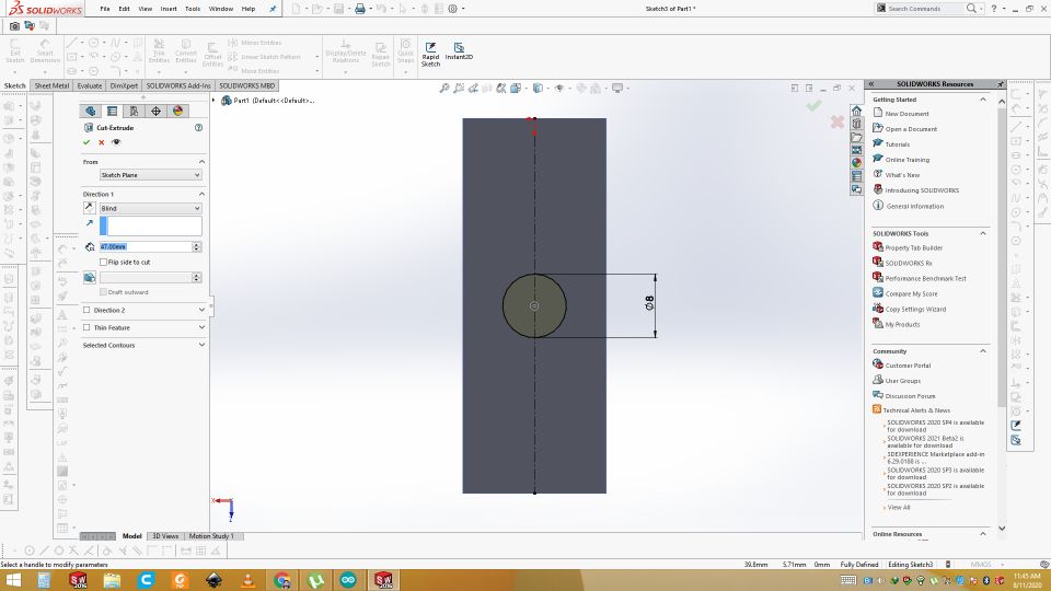
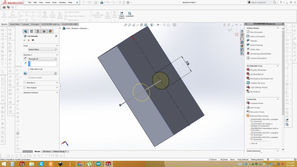
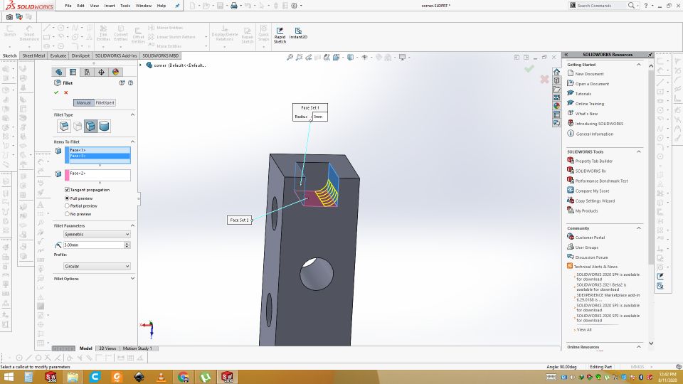
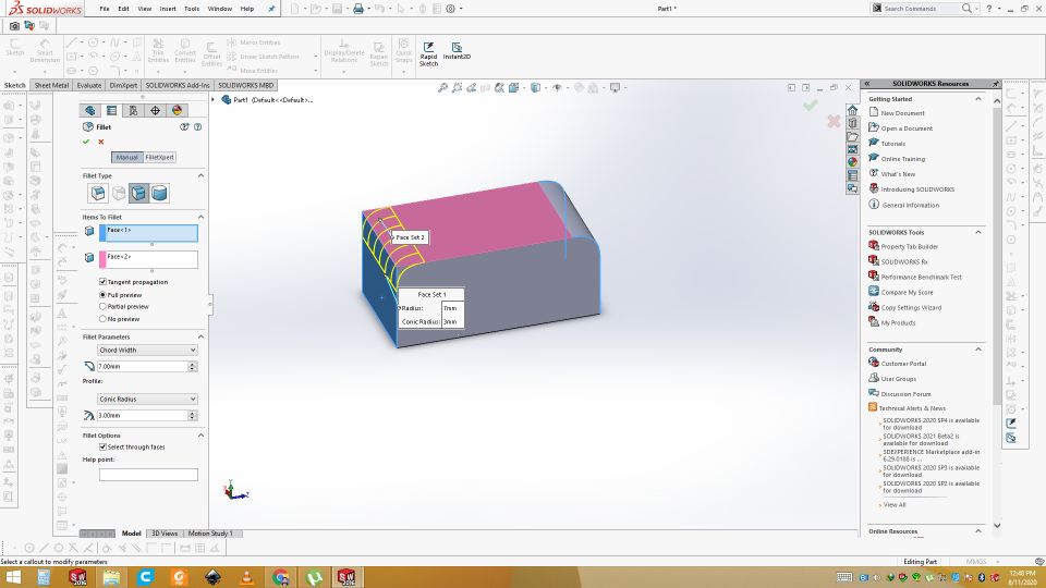
Now draw two circle of 8mm on the side of the part. Extrude though cut the the circle for x axis fixing. Then draw the reactangle of 8mm width. Extrude cut it to 8mm. After that Fillet the Inner side so that rod can be fixed easily.
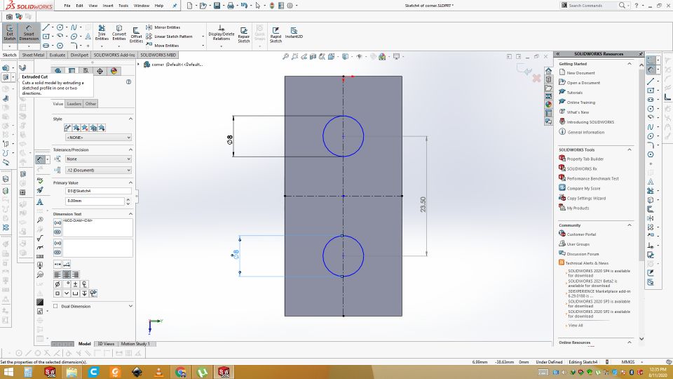
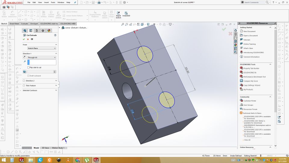
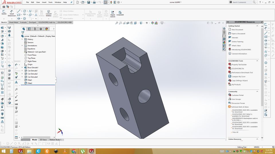
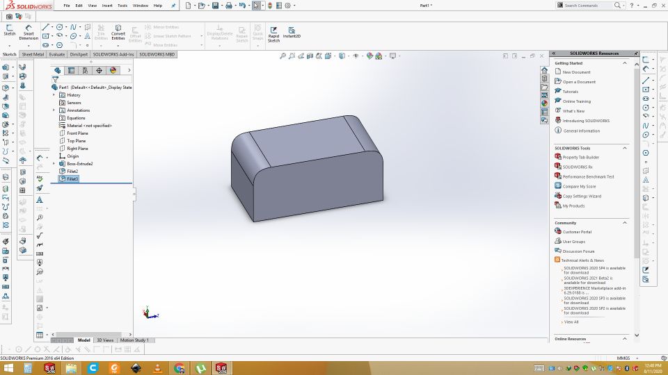
This is the Final Design for the Corners.
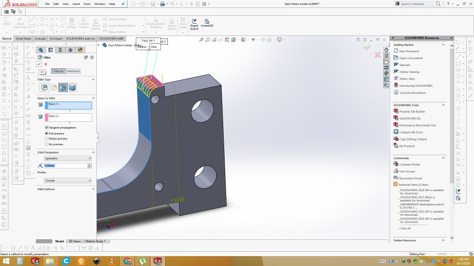
Pully support for the Y axis
Now design the pully support for the y-axis. So draw the rectangle and extrude it. Use the fillet to fillet the both corners.
Draw the rectangle on the top and extrude cut through all. Select the side and draw circle of 3mm on the side and extrude cut through all for the fixing the pully. Draw another circle on other side of 8mm and extrude cut it.
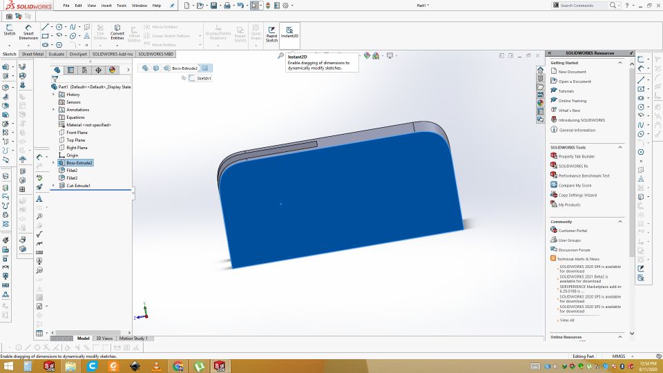
Final design of pully support for the Y axis
Stepper motor stand for the Y axis support
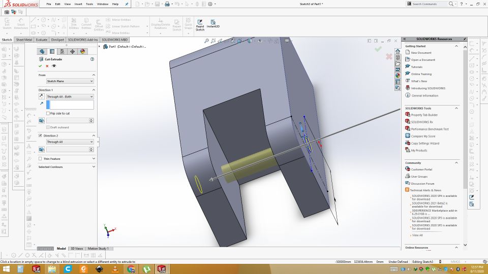
Same Process apply for all design so now design the stepper motor stand for the Y axis support. Draw and extrude cut the two holes for support. Cut the unnecessary area and then fillet the corners.
Final design of stepper motor stand for the Y axis support
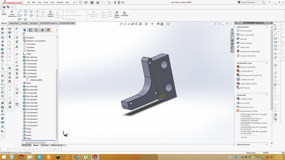
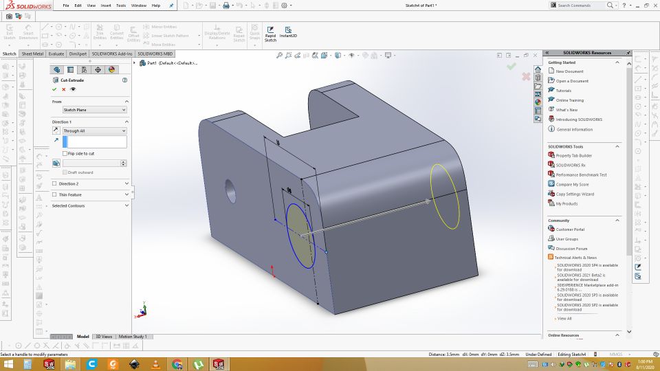
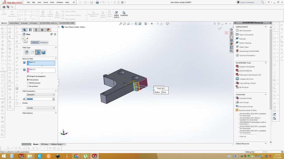
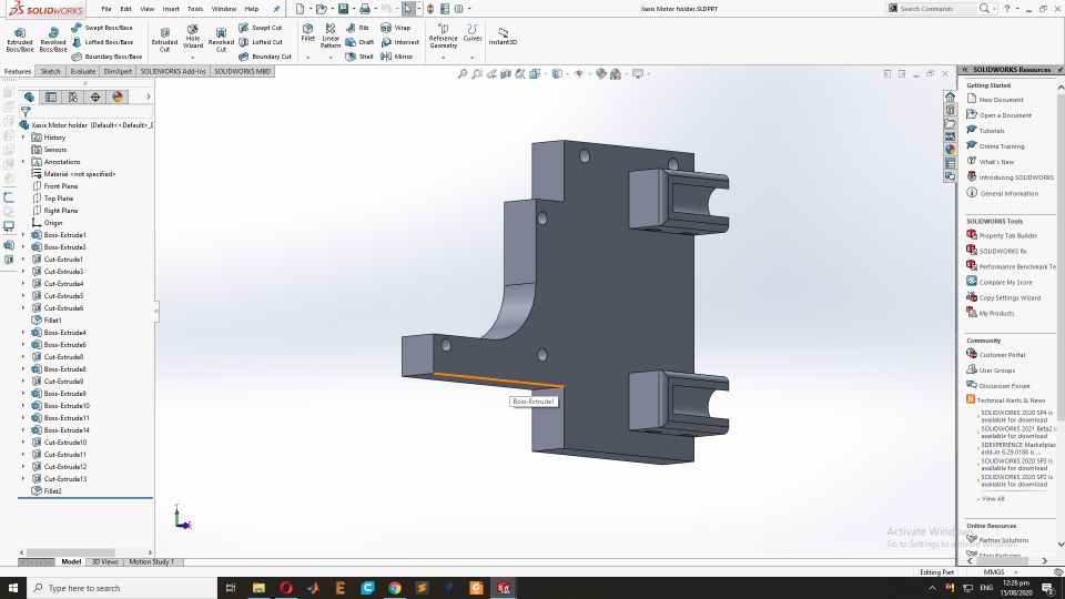
Stand for the X axis Motor
Now design the Stand for the X axis Stepper motor by above same process in solid work. This is the final resul
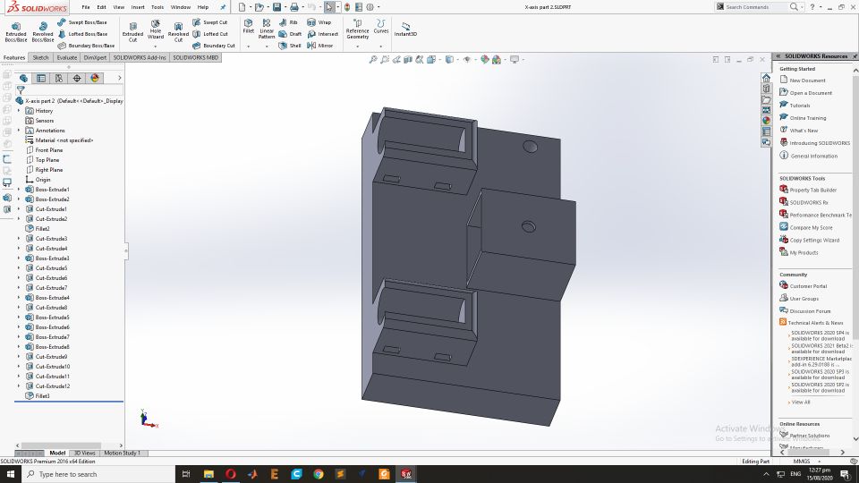
Pully stand on the opposite side of for the X axis Motor
This is part of X-axis. It lays in the opposite of X-axis motor where belt of X-axis will be connected with pully.
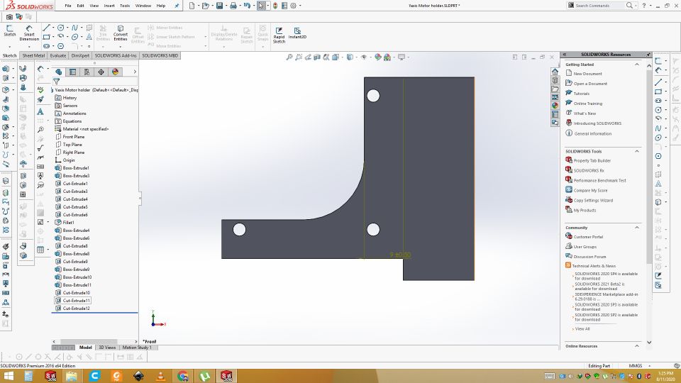
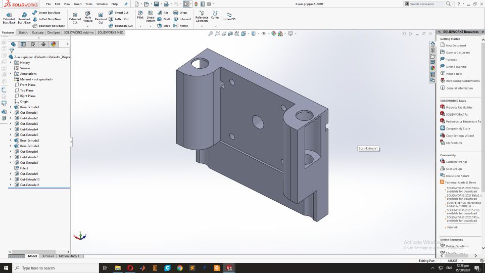
Z-axis motor connecting part
This part will be connected with Z-axis motor on which end factor(pen holder) will be placed.
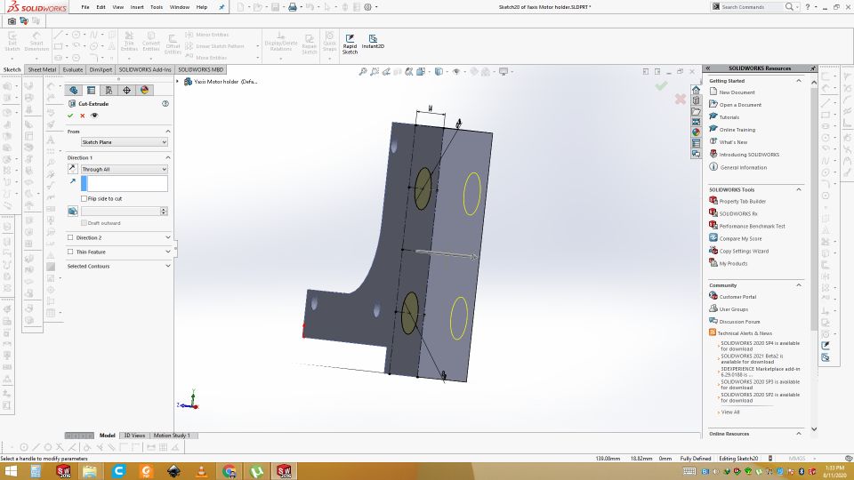
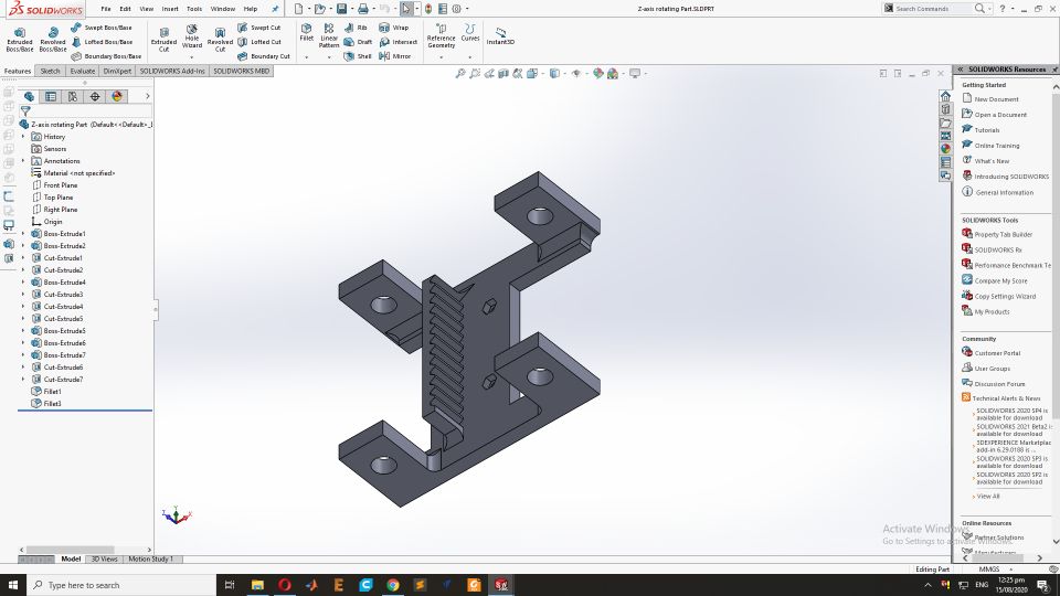
Moving part of Z-axis
This part will be connected with above part and pully on the z-axis motor will make it move up down.
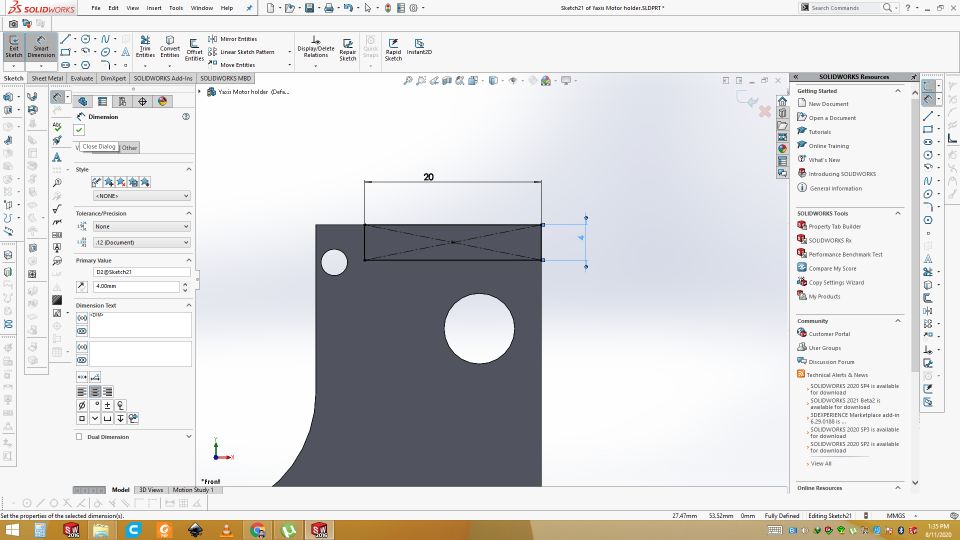
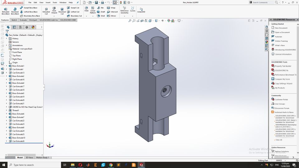
Pen holder
This part will hold the pen. Using screw pen will be fixed. This part will be connected with above part to make complete end factor.
3D printing the parts
These all parts are design in Solid Work and save as .stl formate. Then all these opened in Cura software. From there gcode is generated. That gcode is given to the 3D printer. We are using Ultimaker 2+. Printing of parts of the 2D CNC plotter is shown in video.
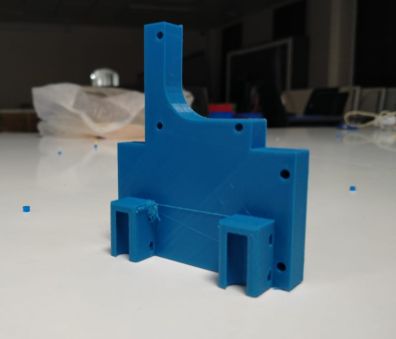
Result
This is result of 3D printing. All the files are printed in this way.
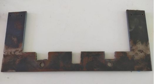
Material Required for the Gantry Structure.
Following are the metalic material which is required to make cnc plotter.
16x16 inches U Shaped Metal Stand for the Plotter support
8mm Iron rods(14inches long and 8 inches) with barrings
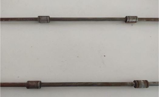
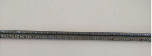
8mm Threaded rods with 16inches long
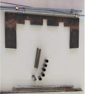
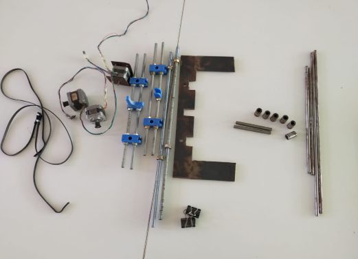
Overall matalic material
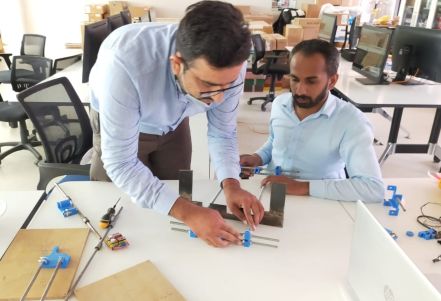
Assembly
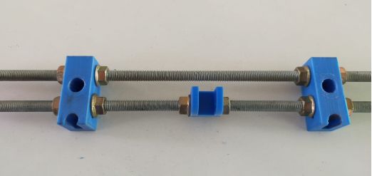
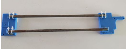
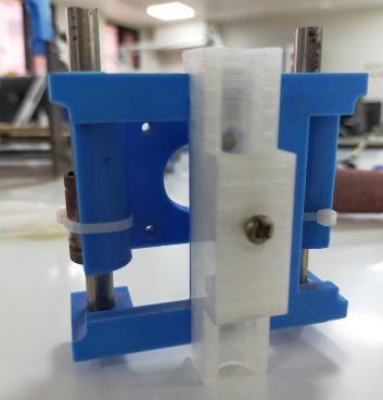
First we need to setup the threaded rods and 3D printed parts. Insert the 3D printed parts into the threaded roads for the base and pully support.
the Second side of the base stand for the Stepper motor that used as the Y axiss.
this is the overall Iron material required for the 2D CNC plotter and with steper motors.
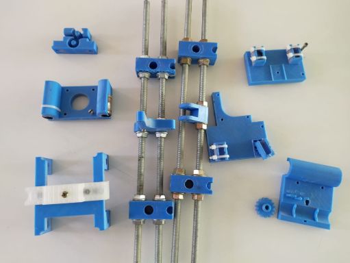
3D printed parts after printing and Assembling the with threaded rods
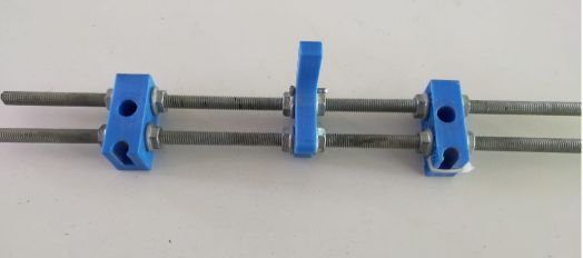
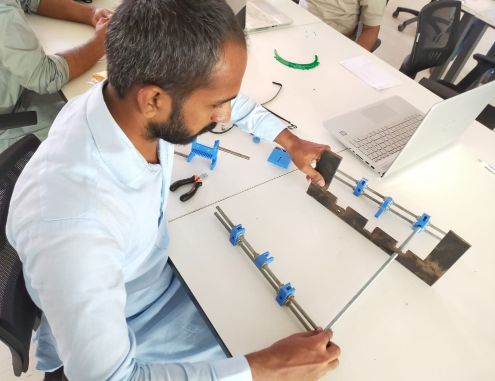
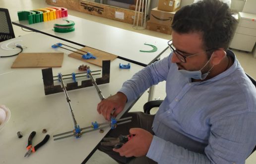
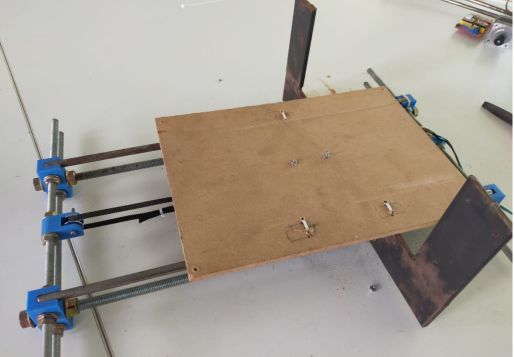
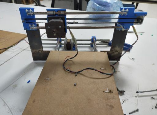
Now we have start to assamble the base of the plotter so first we have assembled Iron rodes with 3D stand parts and then fixed with U shaped Stand.
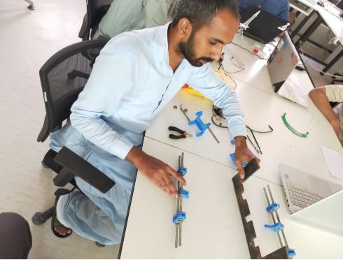
While the Assambly of the Base.
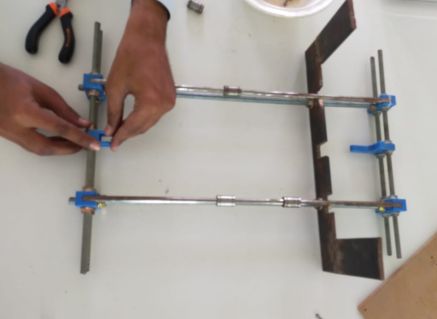
We have fixed base stand and rodes with Nuts.
Fixed the stand with nuts. Now the Base of Plotter is alomost ready.
Now we have fixed the Pully for the Y axis.
Now time to fixed the Stepper motor for the Y-axis movements.
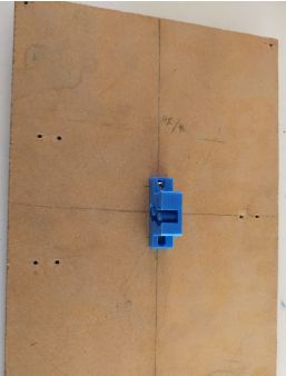
This is the Paper stand where paper is fixed for the sketch.
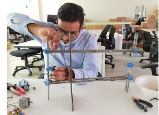
We have complete the Gantry Structure of the 2D plotter.
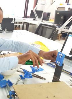
Now we have fixed the Stepper Motor for the X-axis dircetion. This is the upper Arm after the fixing the Iron Rods.
Now we have fixed upper Arm with the Plotter Stand.
After the Fixing the Upper Arm now we have also fixed the Stepper motor for the Z-axis(end factor motor).
Assembly for end factor(Pen holder). This will be fixed to the z-axis motor.
Assembly is done
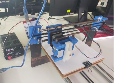
Manual working of plotter
Electronics
Now it is time to add electronics to make it automate and actuate. For microcontroller i am using Arduino UNO board and for motor driver we are using cnc sheild for arduino uno.
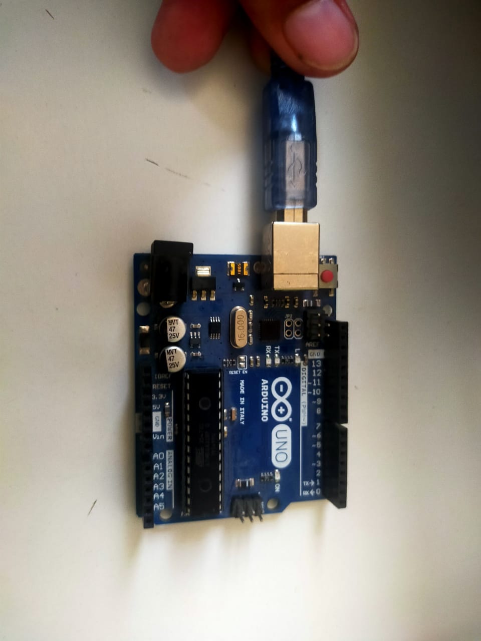
Arduino UNO
The Arduino Uno is an open-source microcontroller board based on the Microchip ATmega328P microcontroller and developed by Arduino.cc. The board is equipped with sets of digital and analog input/output pins that may be interfaced to various expansion boards and other circuits.
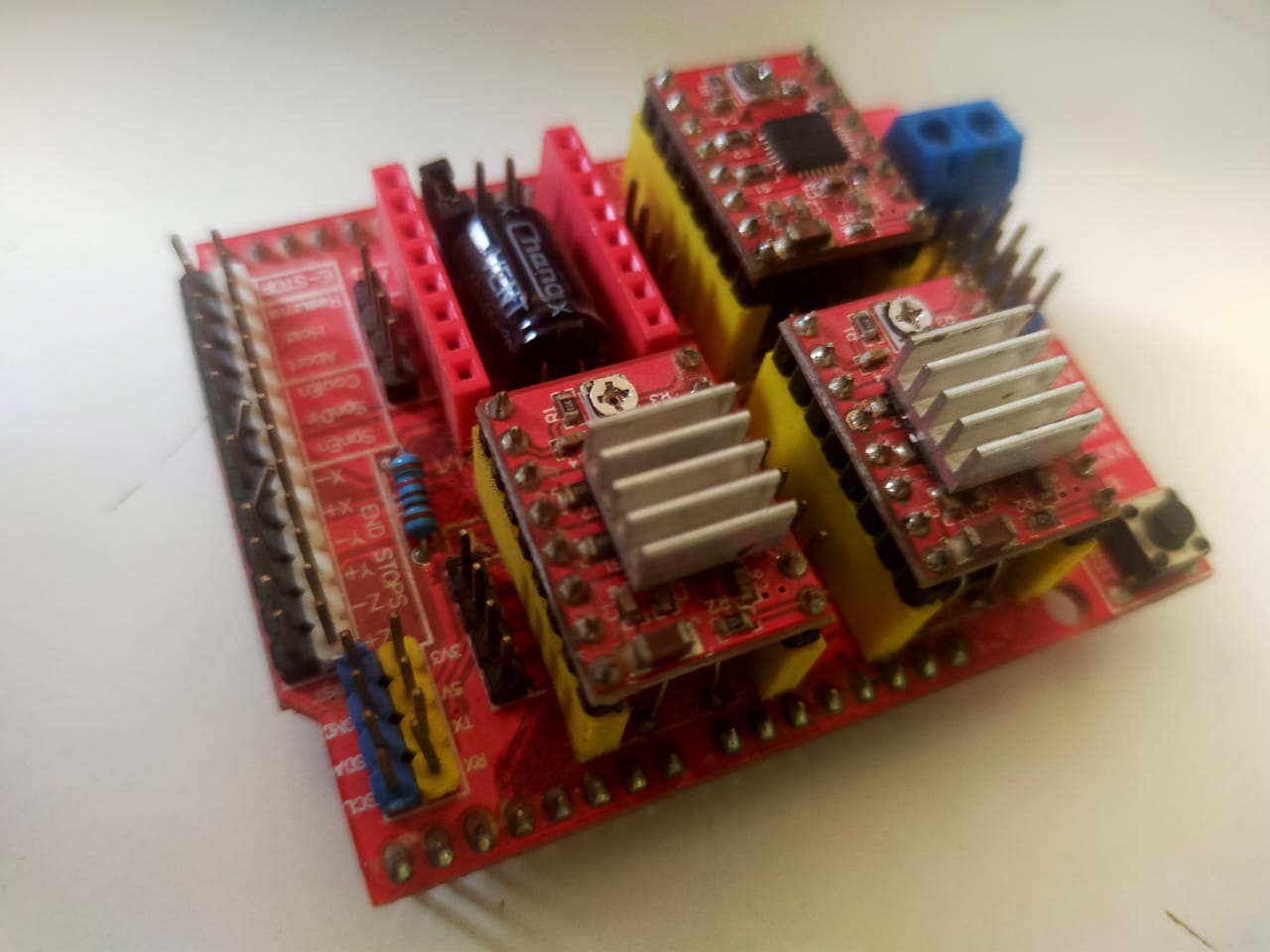
CNC sheild for Arduino UNO
Arduino CNC shields provide an Arduino microcontroller with the power necessary to drive stepper motors and run all the other functions that contribute to a CNC machine's operation. Depending on the shield, this could include end stops, spindle speed control, and probing.
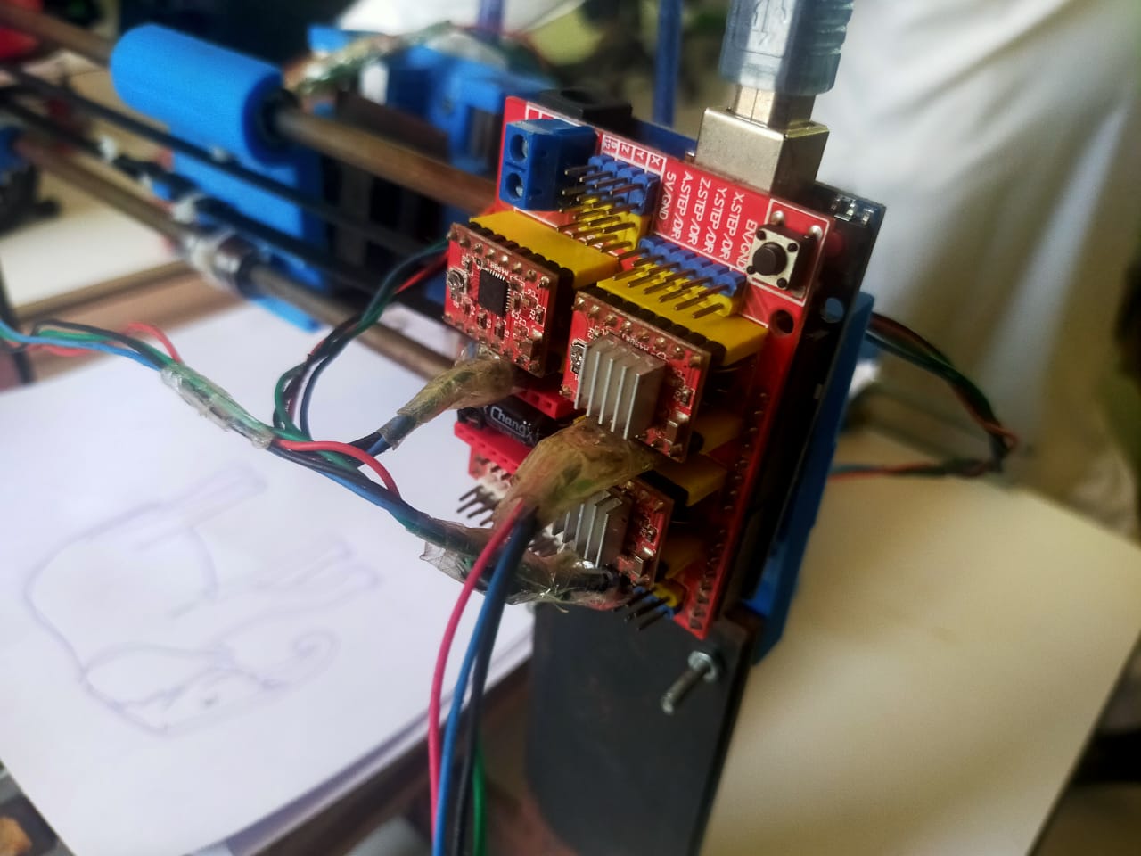
Fixing and Connections
First of all fix the cnc sheild on top of the arduino. Attached it to the CNC plotter and connect the motor wires to the CNC sheild. Connect the arduino with PC via USB cable.
Software
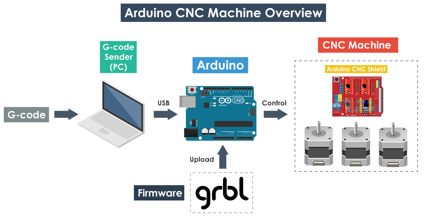
After setting all the hardware connections and assemble, now it is time to setup the software for CNC Plotter. Below attached the Arduino CNC machine overview.
GRBL
GRBL is an open source software or firmware which enables motion control for CNC machines. We can easily install the GRBL firmware to an Arduino and so we instantly get a low cost, high performance CNC controller. The GRBL uses G-code as input, and outputs motion control via the Arduino . From the diagram we can see where the GRBL take place in the “big picture” of the working principle of a CNC machine. It’s a firmware that we need to install or upload to the Arduino so it can control the stepper motors of the CNC machine. In other words, the function of the GRBL firmware is to translate the G-code into motor movement.
G-code
G-code, which has many variants, is the common name for the most widely used computer numerical control programming language. It is used mainly in computer-aided manufacturing to control automated machine tools. G-code is a language in which people tell computerized machine tools how to make something.
How to install GBRL
First, in order to be able to install or upload the GRBL to the Arduino we need the Arduino IDE. Then we can download the GRBL firmware from github.com . Download as .Zip. Extract the gbrl-master.zip. Open the Arduino IDE, navigate to Sketch > Include Library > Add .ZIP Library. Navigate to the extracted folder “grbl-master”, in there select the “grbl” folder and click the open file. Now we have to GRBL as an Arduino Library.
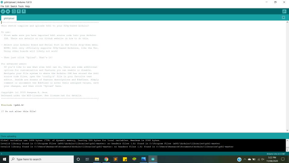
Upload the firmware
navigate to File > Examples > grbl > grblUpload. A new sketch will open and we need to upload it to the Arduino board. Don't worry code has only one line. Connect the arduino. Select the port and click upload. Done uploading. Now your arduino can understand the G-Code.
testing
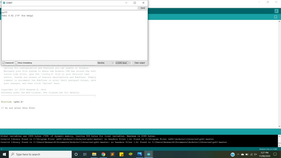
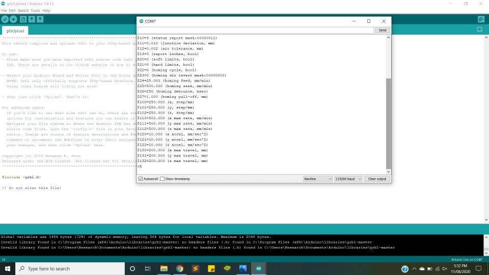
Open the serial monitor and set the baudrate 115200 and enter the "$$" in serial moniter. List of command will appear. This shows that firmare is install correctly.
G-Code Generation
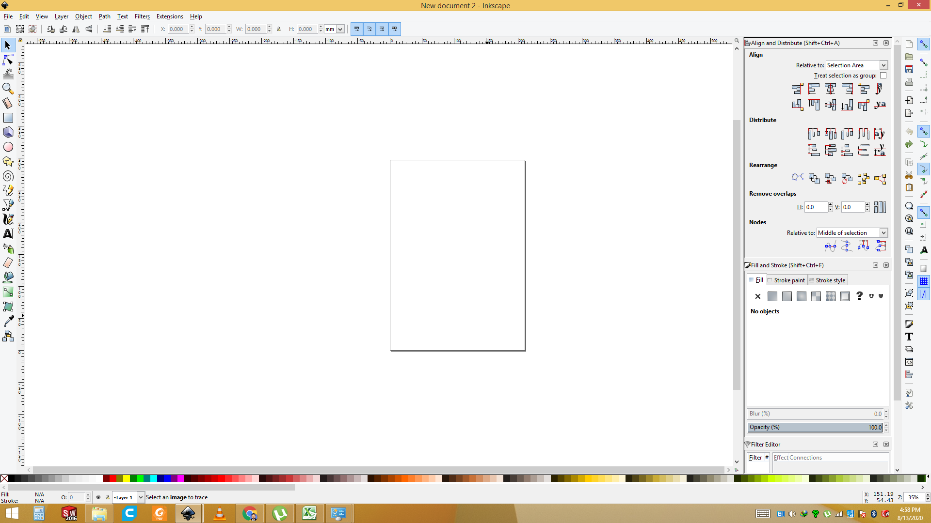
We have use the inkspace software to generate the G-code. Open the Inkspace software
Import the Image that you want to plot.
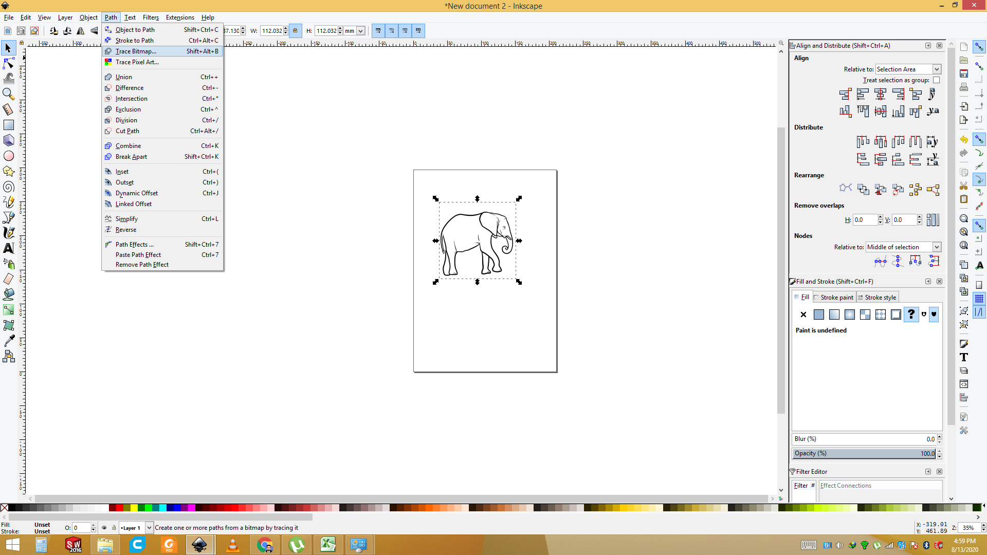
Now we have set the Bit map trace to generate the Vector of the Image.
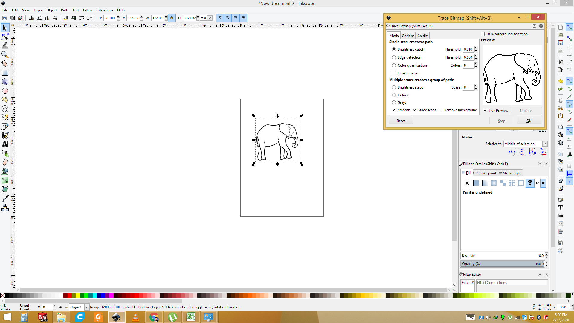
Go to the Tool and select the Bitmap trace and press OK command and add to the layer .
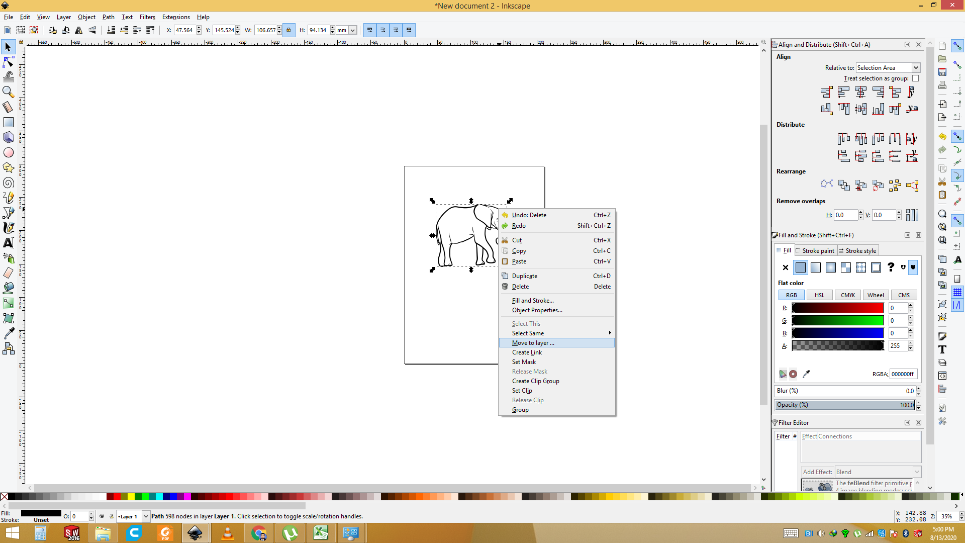
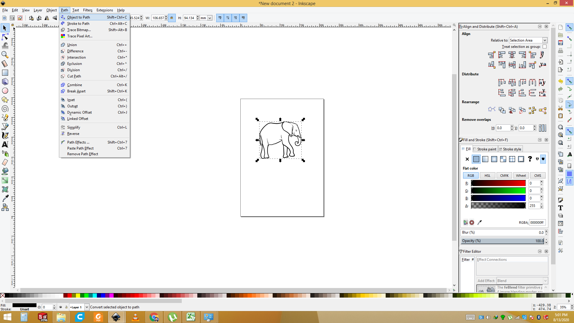
Now add the Object to path so first select the Image then go to path and select the "add to the path".
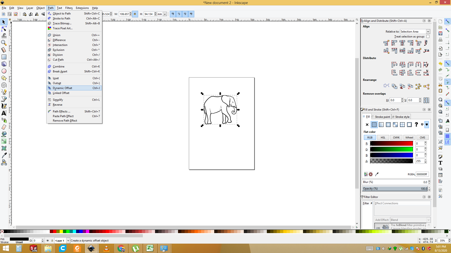
Now go to the path and select the dyamics Offset or press the "ctrl+J".
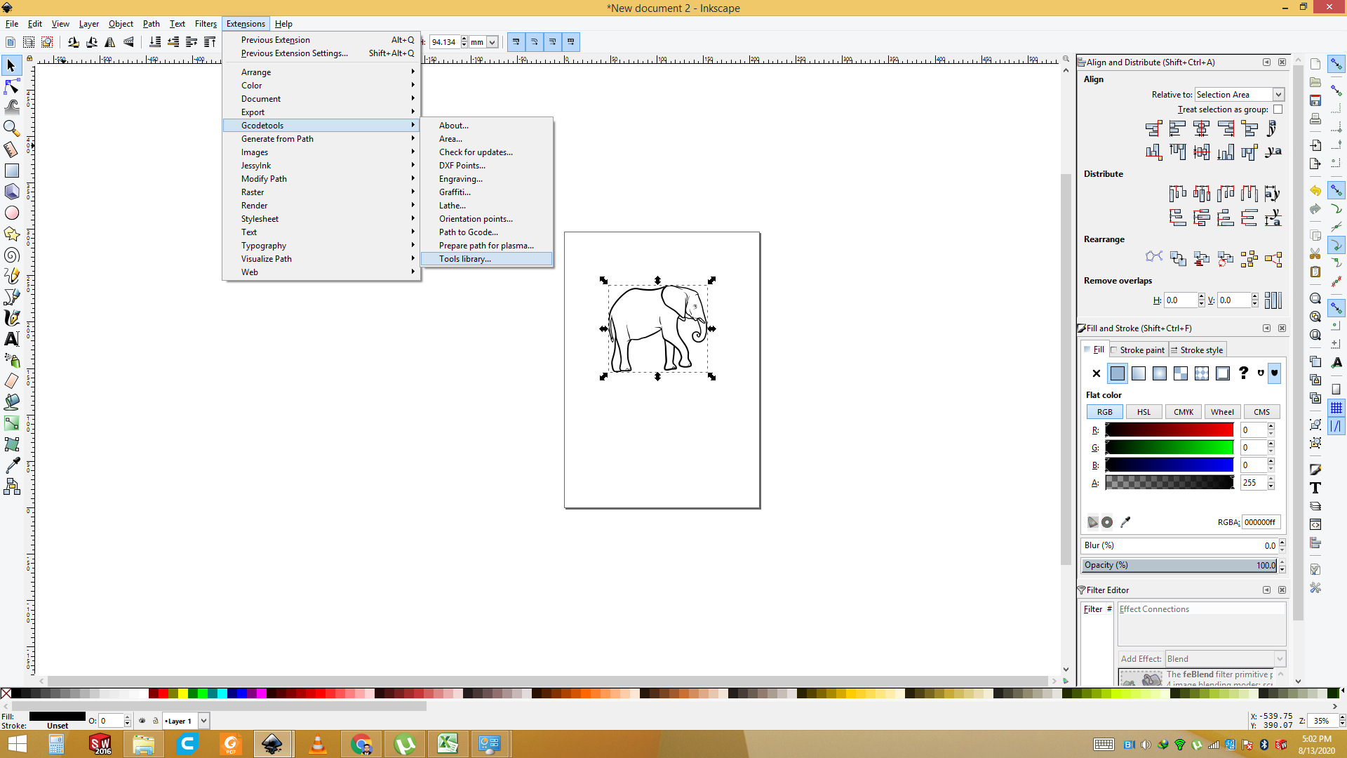
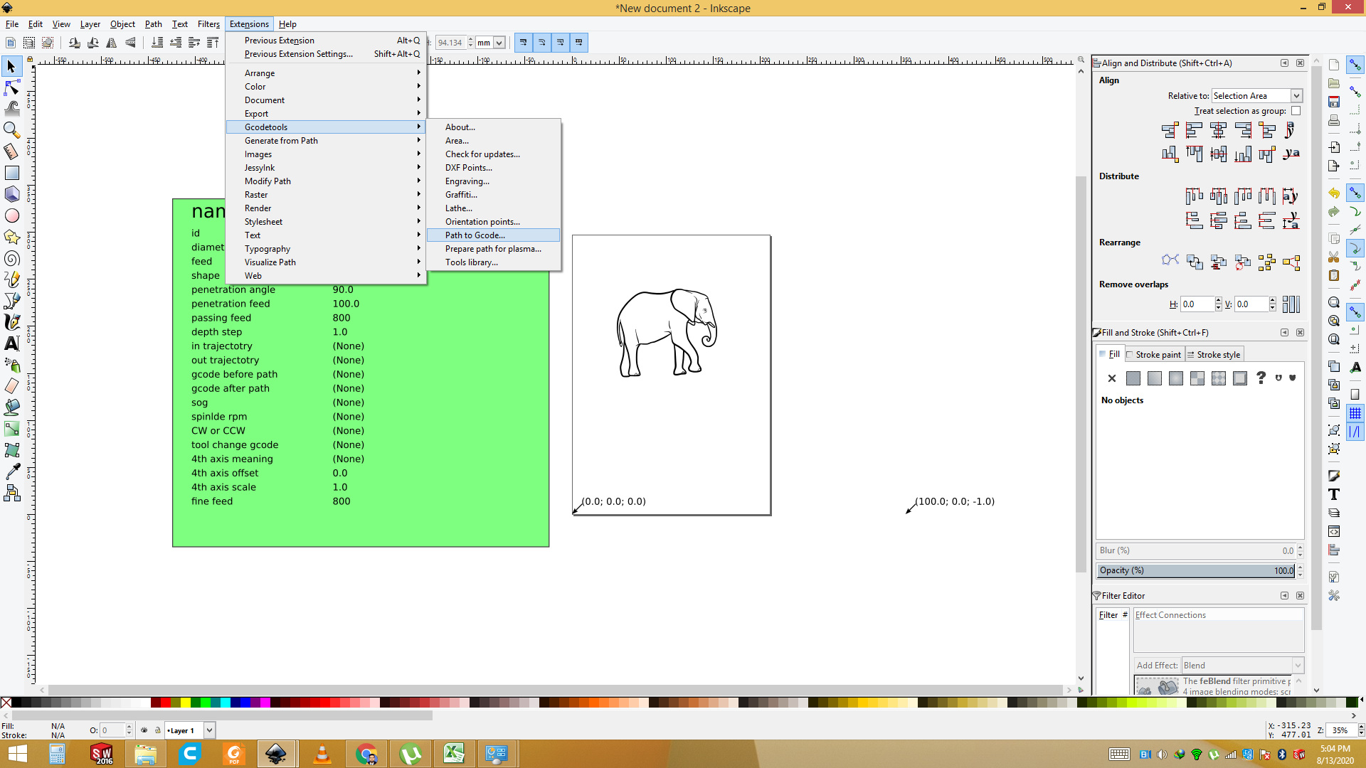
Now go to the Extension sand select GcodeTool for the G code generate.

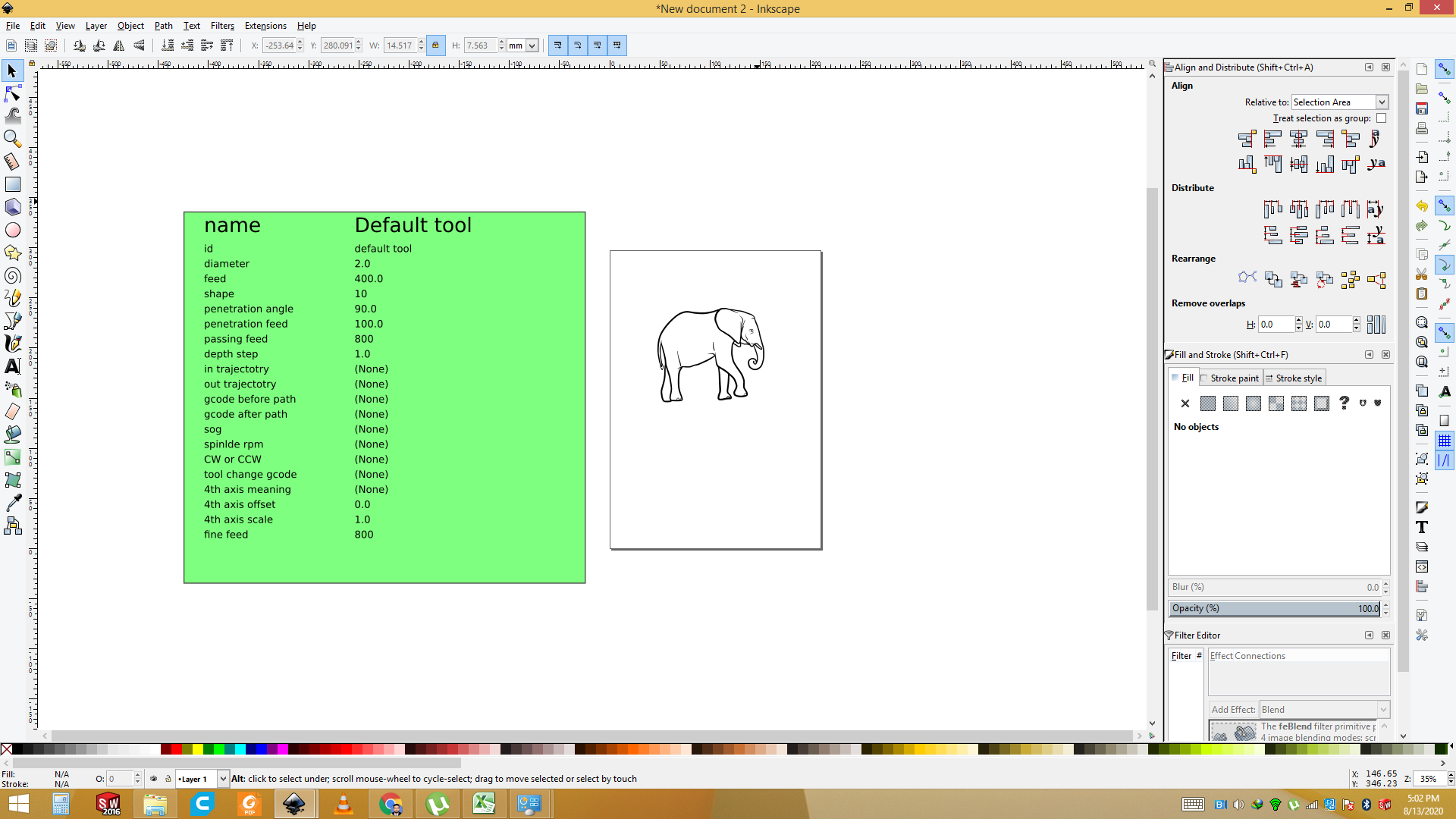
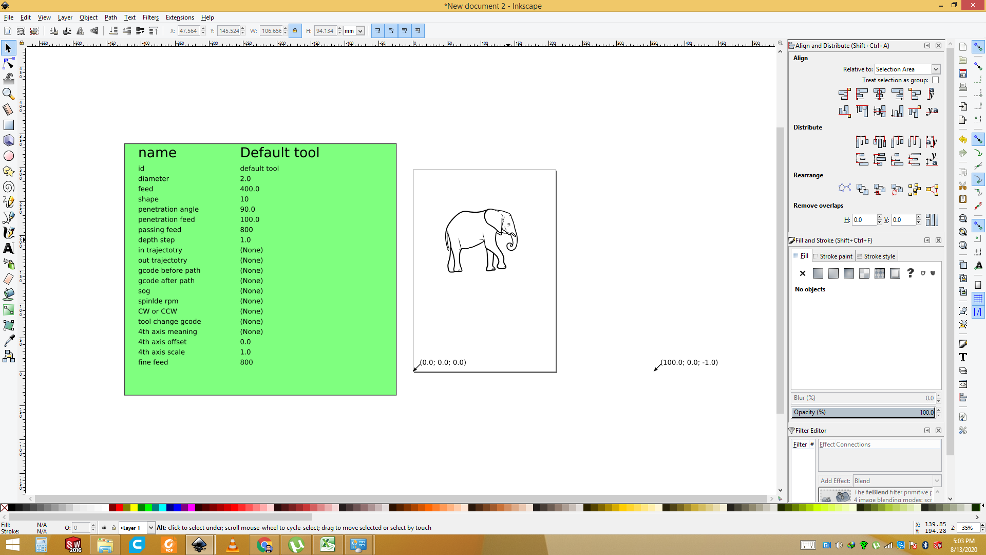
Now go to the Extension sand select GcodeTool and Select the " Tool library ".
Now set the diameter " 2.00"
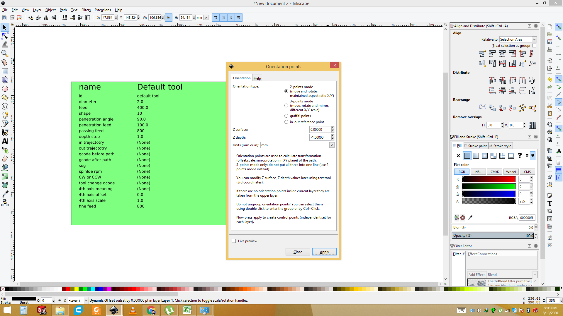
Goes to the Extension and select the "G code Tool " and set the Orientation point of the Image.
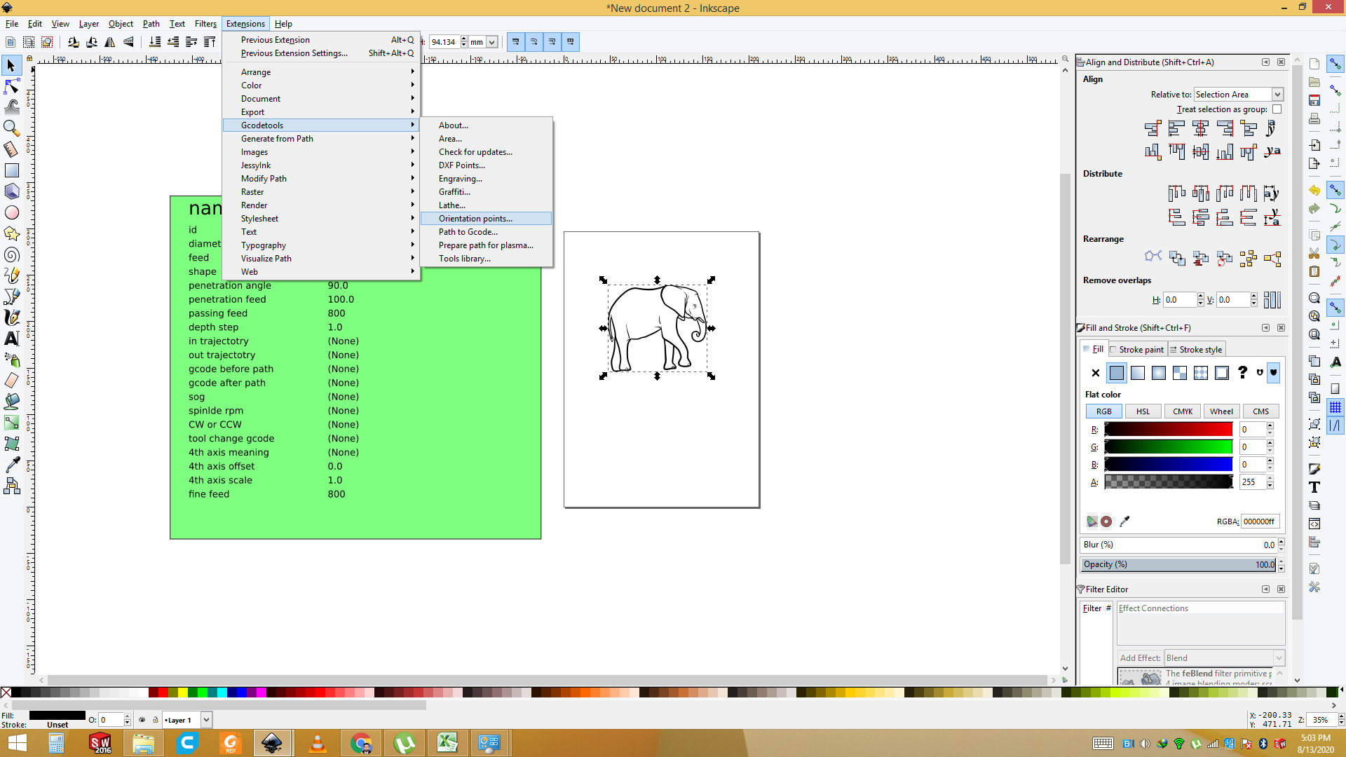
set the Orientation point of the Image and Apply it.
the result of the set the Orientation point of the Image.
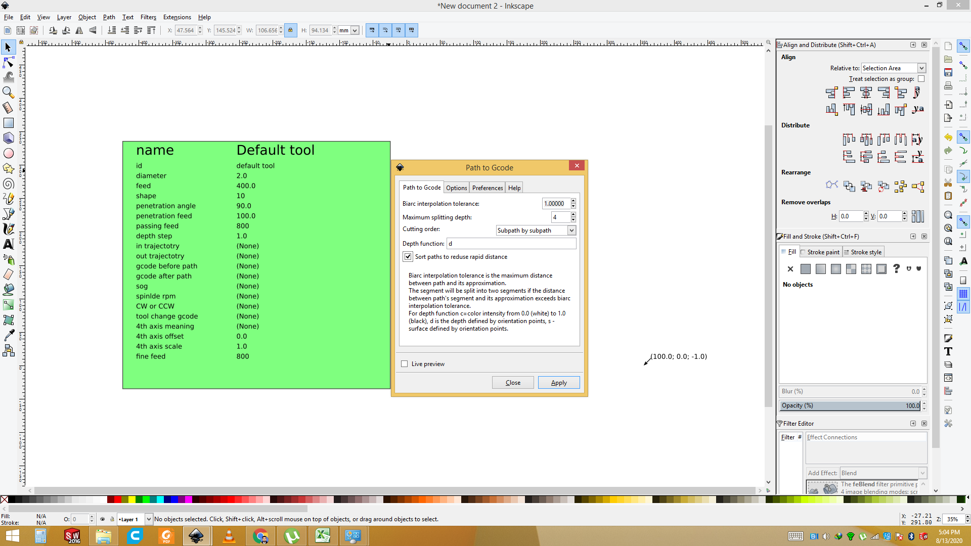
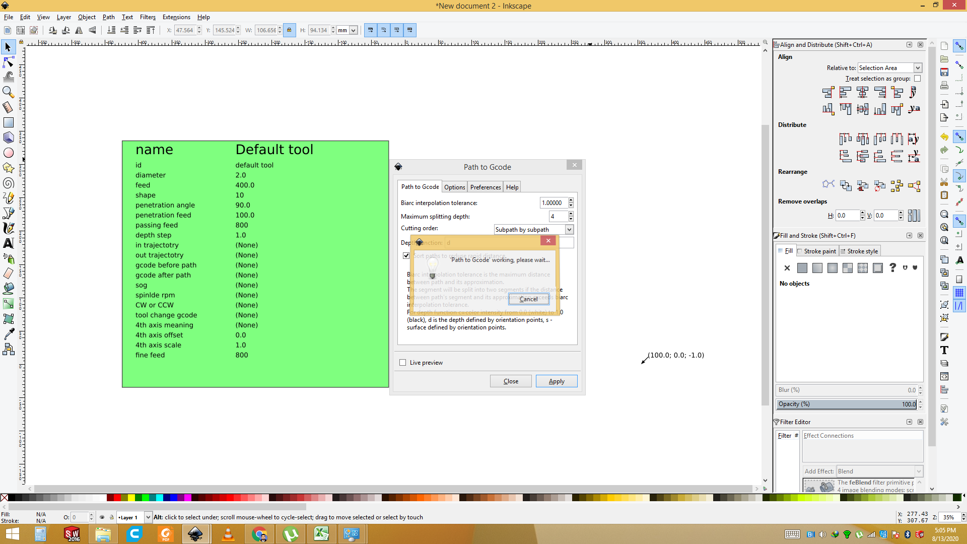
Goes to the Extension and select the "G code Tool " and set the path to G code.
Now Press the Key "apply".
Now set the "Preferances " and name the file then apply it.
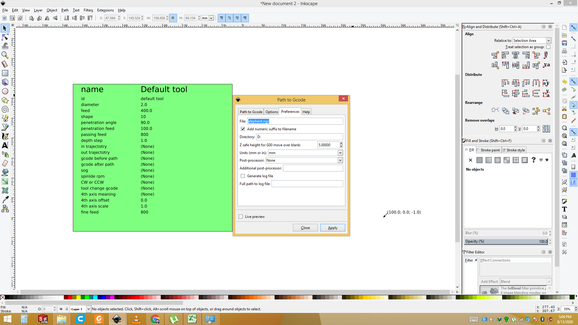
Now G code is generate and its working.
Now File is ready change the name save it.
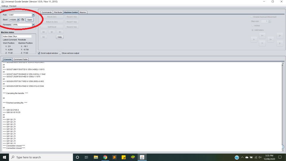
Universal G-code sender
Universal G-Code Sender is a Java based, cross platform G-Code sender, compatible with GRBL, TinyG, g2core and Smoothieware. You can download from here This is used to setup the plotter and it also used to send the gcode to the plotter via com port. First of all select the Port in which arduino is connected( "Com-07" in my case). Select the baudrate 115200 and click on "open". This will connect our software with our plotter. If every thing is fine you will get "connect with port..." in command line.
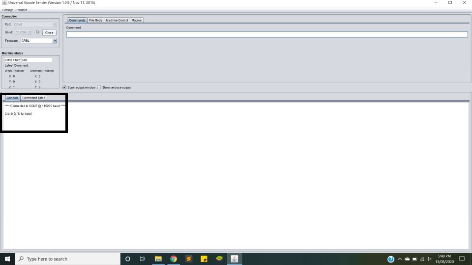
Universal G-code sender connected with plotter
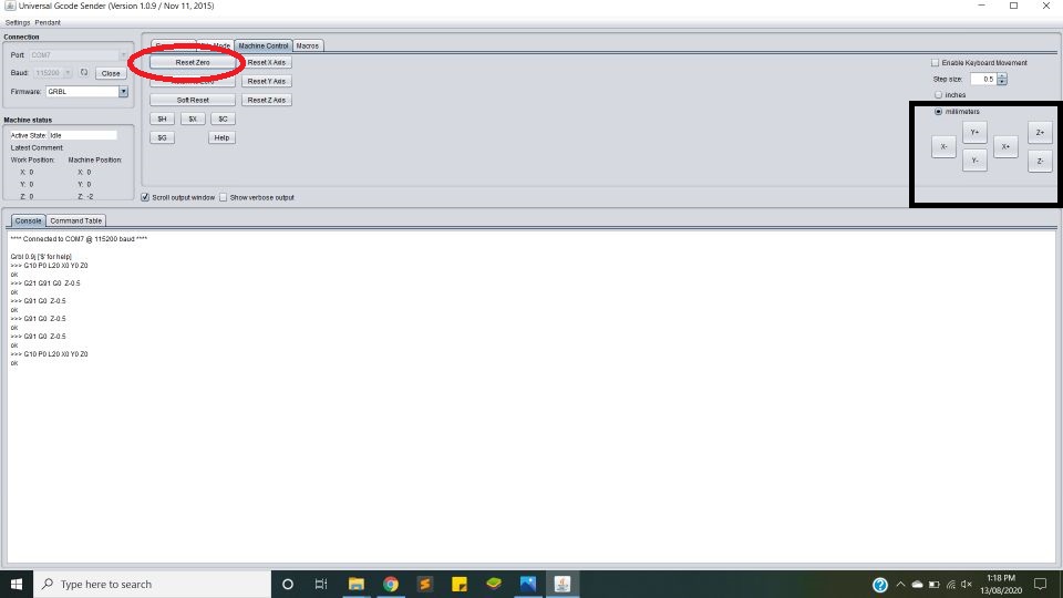
Set X,Y and Z zero
Open the machine control. Jog the machine using the arrow key. Move the head of plotter to desired location from where you want to start the sketch. Click on "reset zero" will set the Origion of the Plotter.
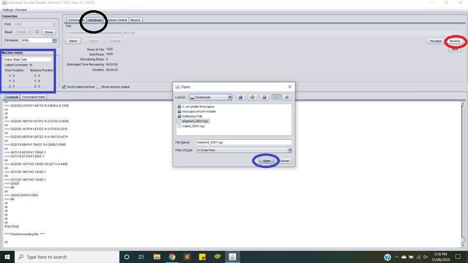
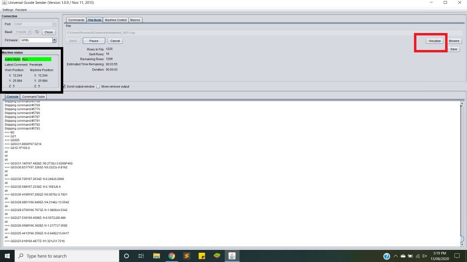
Upload the gcode file
Open the file mode. Click on browse and navigate to the gcode location. Select the desired G-Code and click "Open". This will load G-Code into the software. Then click "send" will send the data to the microcontroller and microcontroller will move the motors accordingly. You can visiualize the gcode by clicking on visiualize button. It will show run time position of header on simulator.
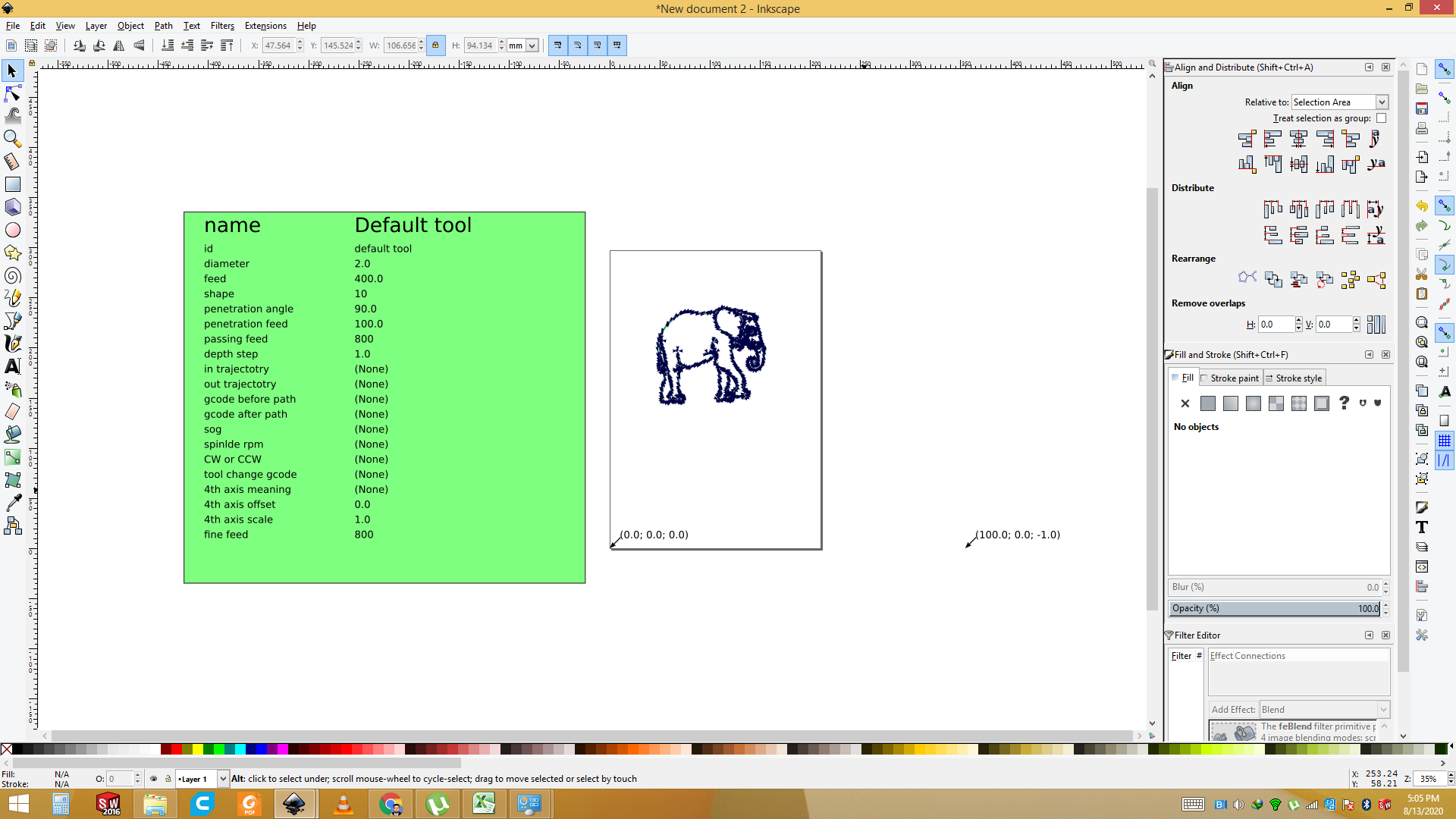
Final Demo Video of the Plotting of Elephant
Now plotter is ploting the shape of elephent.
Final result

Improvements in Future
This is the first version of the plotter. It is working fine but can be improved in many areas. First thing which we want to see in future if any other person wants to work on it, is to add multiple pens in the header. It will be great thing to watch if the sketch made of multi-color pens. Automatically one pen goes up and the other comes down and starts sketching. Another thing is smoothness in movement. It is working smoothly but sometimes there is some jerk in it. Stepper motor can be replaced with BLDC motor for faster working. Writing area is A4 size. This can be increased as well.
Download all files from here

This work is licensed under a Creative Commons Attribution-NonCommercial-ShareAlike 4.0 International License.