
Assignment
- Design and build a wired &/or wireless network connecting at least two processors
Individual Assignment
In this week task is to design and build a network connection ,So I have planed to design the ESP-12E Module board.In this week I mentioned the making of programmable ESP-12E board
ESP-12E Module:
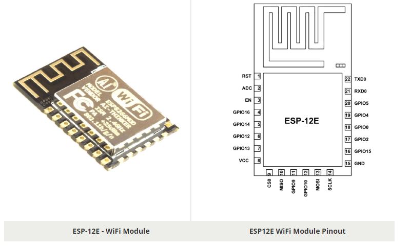
ESP-12E is a miniature Wi-Fi module present in the market and is used for establishing a wireless network connection for microcontroller or processor. The core of ESP-12E is ESP8266EX, which is a high integration wireless SoC (System on Chip). It features ability to embed Wi-Fi capabilities to systems or to function as a standalone application. It is a low cost solution for developing IoT applications. For more details and Data Sheet is Available HERE
This the Pin DiaGram of the ESP-12E Module.
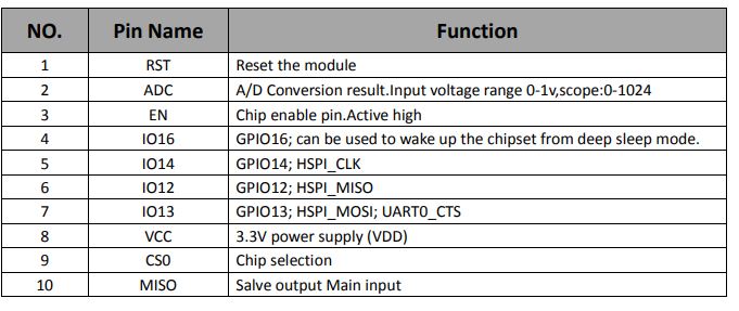
The ESP-12E module has twenty two pins and we will describe function of each pin below.
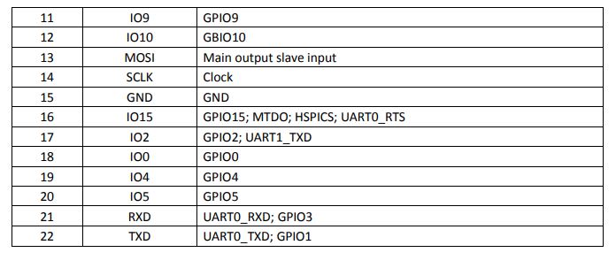
ESP-12E Module PIN Configuration
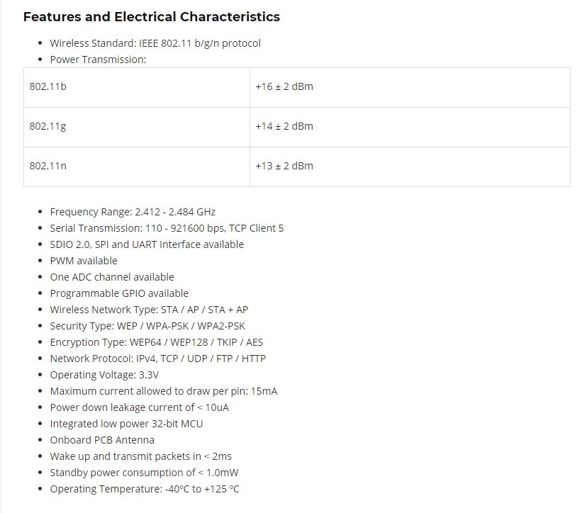
Silent Featurs of the ESP-12E Module and Electrical Characterist
How to use the ESP-12E
This module does not have complex circuitry or programming so using this module is very easy. We will construct a simple application circuit for understanding the module working.
These are the Steps for setting up a simple application circuit:
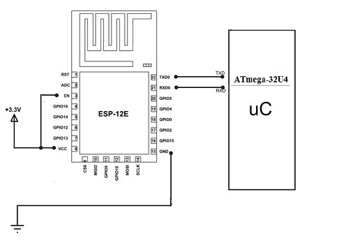
This is the Block Diagram of the ESP-12E Module Interface with Micro Controller Board.
Applications
PCB Design
First I have Select the Circuit Which I have to Design in Eagle CAD, After that, I have Download the ESP-12E Library from and upload it on the Eagle CAD Software. HERE
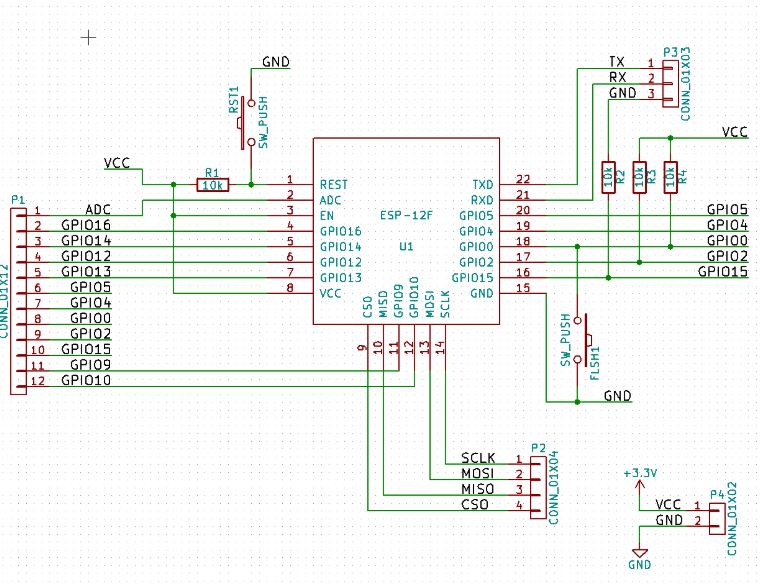
After the research , I have found this circuit to design in CAD. HERE
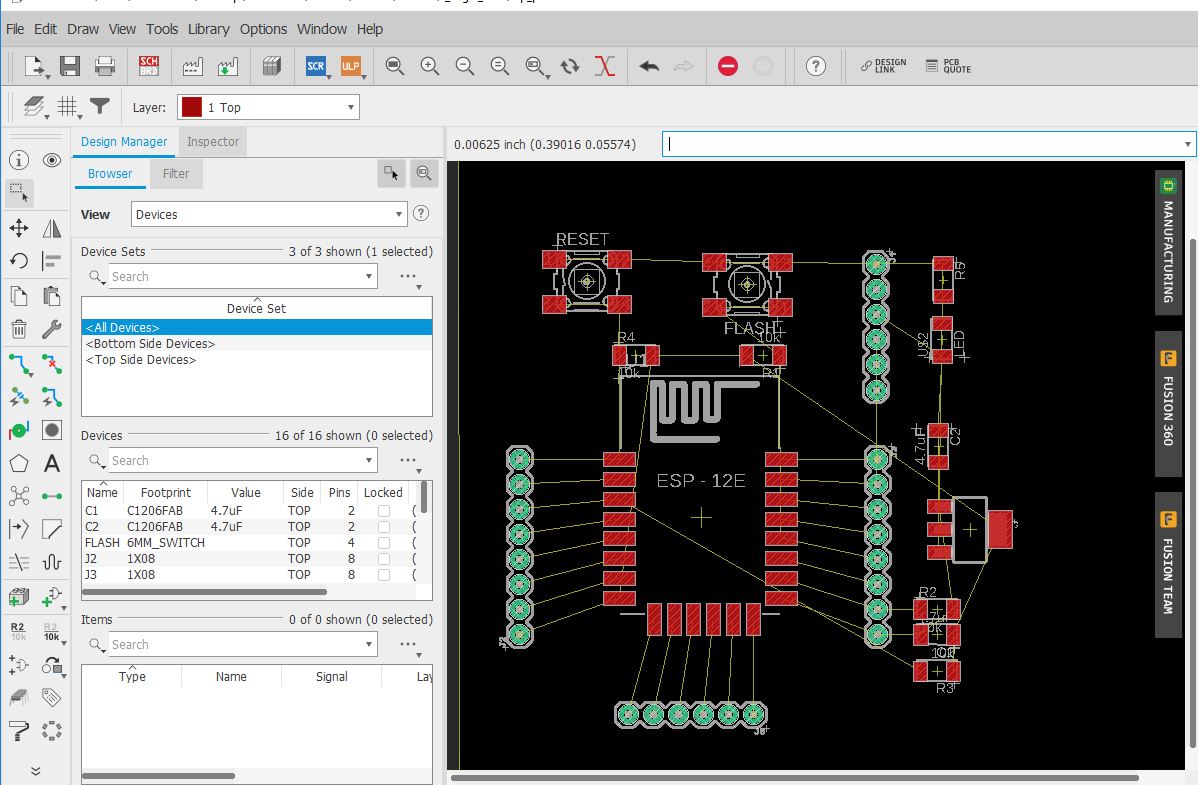
After the adding ESP libraray in Eagle CAD . I have started to work on CAD Section to design the circuit.
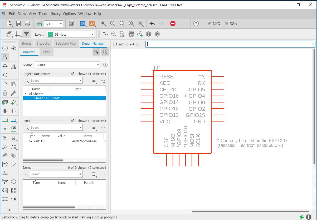
This the ESP Moudle in Eagle CAD.
The CAD design of circuit in Eagle Software
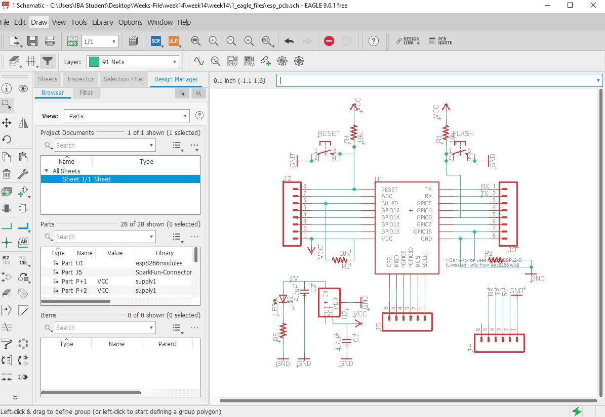
This is placing of components in CAD software
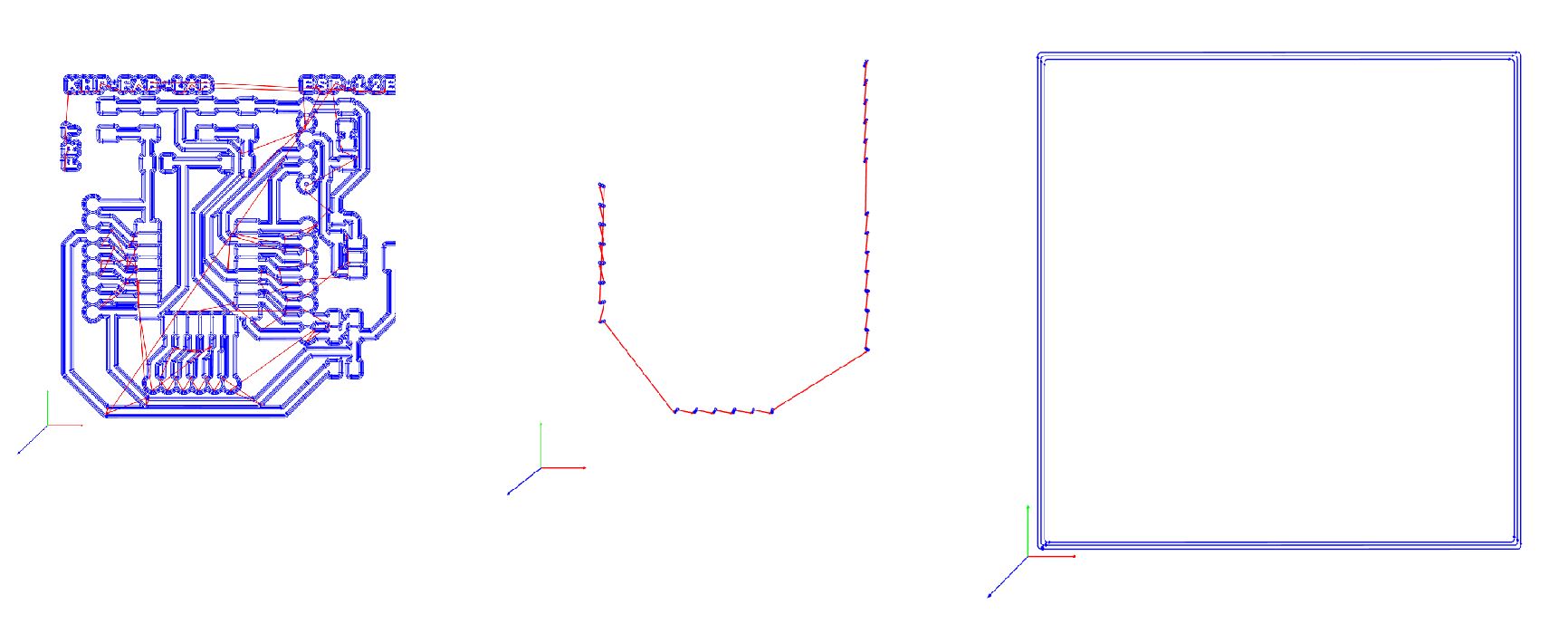
This the complete routing and now board is final for the Milling
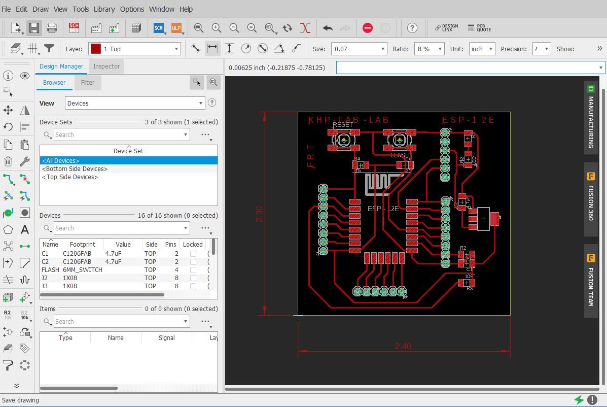
These are the Mono chrome image which help us to generating the RML code
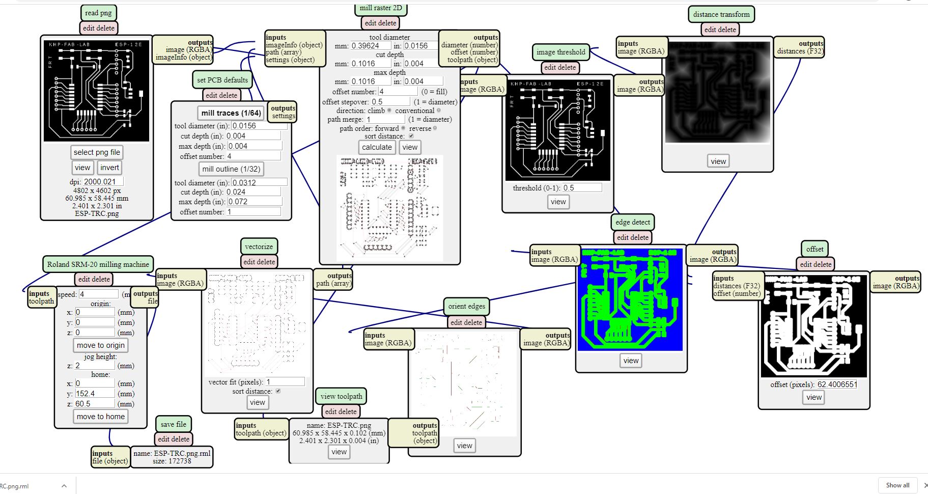
I have Generated the Code by using MODs So here is Link of MODS-USer
By using the MODs , That How we can Generate the RML Code. and this image shows the Trace RML and using the same procedure we can generate the RML code but only the change is that for the Trace we use the 1/64 Tools and while for the Drill and Outer we used the 1/32 tools for the Cut.
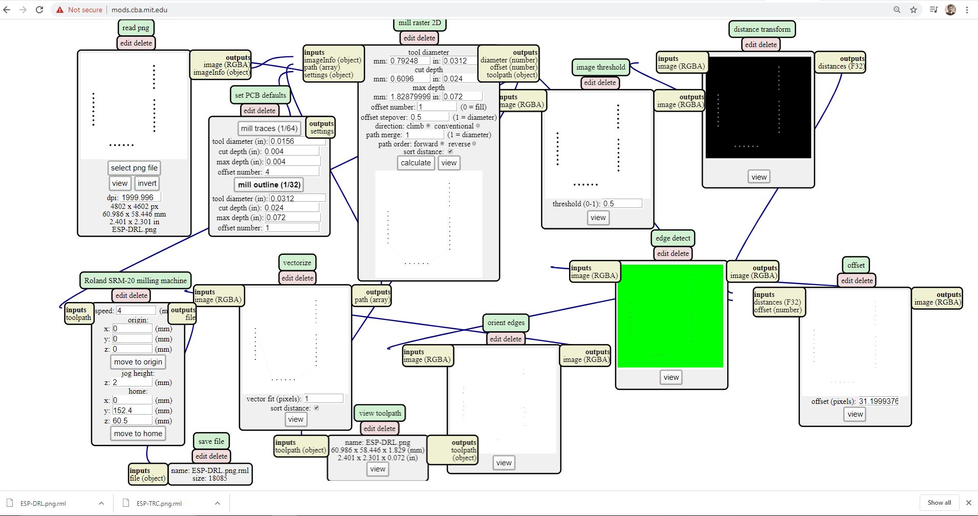
The outer line RML code generating methods
All RML Code of the Design ESP-12E Module
List of Electrical Component required for the Board to soldering
Milling Process using SRM-20
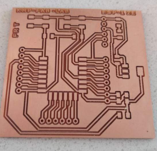
For the milling process, I have used the SRM-20 Machine, First I have set the Origin x, y at zero, and set the place od z at zero, then Set the Bit of 1/64 and give the input to the Machine. So first put the Trace file to the machine, after the completing milling process of trace, then I have to change the tool bit and used 1/32 for the Drill and Outer. this the final board after the milling.
Soldering Process
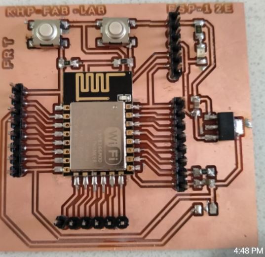
Now the process is the Soldering the Board, So I have Switched on the Solder station and set the temperature at 480C. First I have Solder the ESP-12E Module then other Components, So this the Final Look of the Board is this.
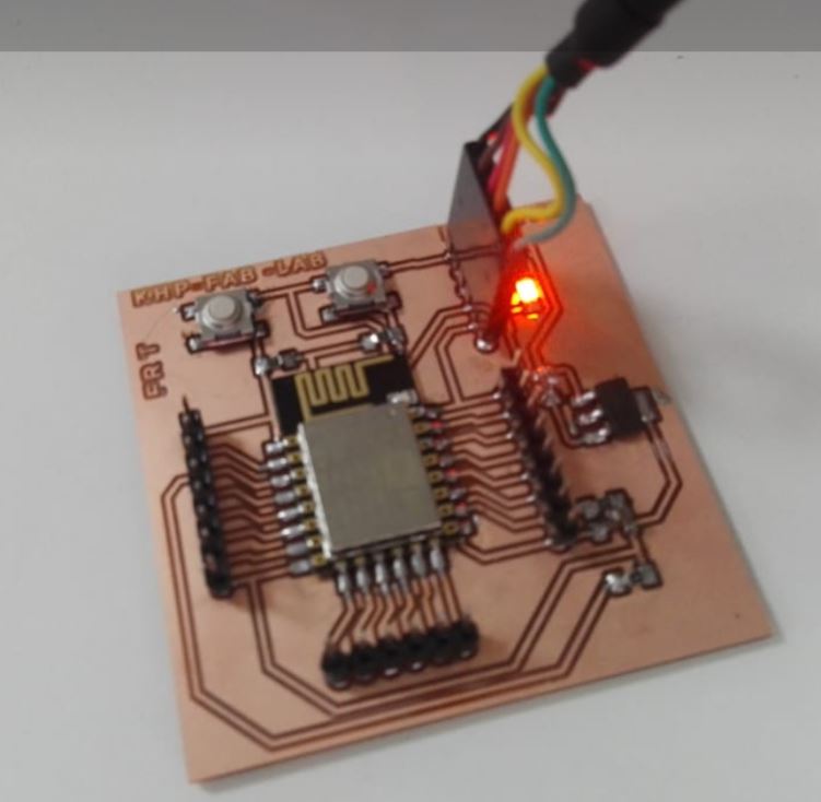
Power up ot the device
I have connected ESP- Module with FTDI cable and connect with the PC to Power 0n the ESP board.
Programing
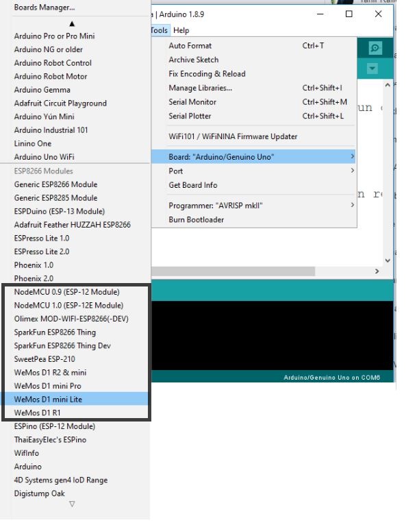
First of all, I have to add the library of ESP Wifi module in Ardunio ID, Before doing with programming I had to include esp8266 library which I added as given => File>Preferences => Additional Boards manager URLs: http://arduino.esp8266.com/stable/package_esp8266com_index.json, in Arduino IDE. Later I went to tools selected boards as node MCU 12e module and few other settings. VISIT THIS LINK FOR MORE DEATILS
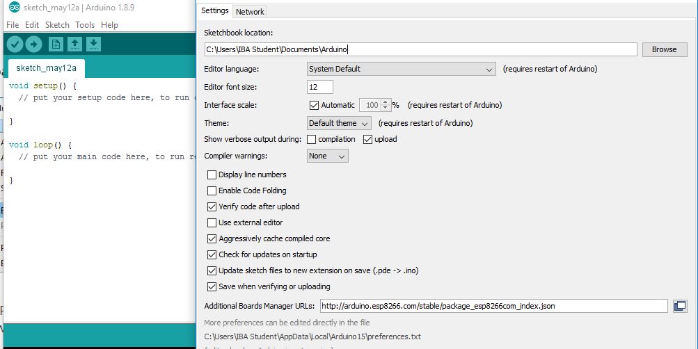
The Installing of Library in Arduino ID
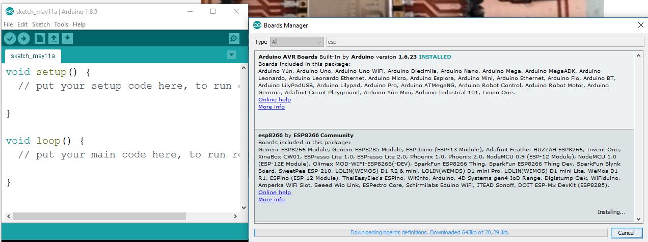
The adding of ESP Library Arduino ID for the ESP micro Controller so found here.
After the Boot load Now ESP board is working. This is the Program which I have to upload the ESP Module, for the communication, I have to change the USER SSID-"Guest Smart University " and Password assigned by Network, after that, I have to Upload it.
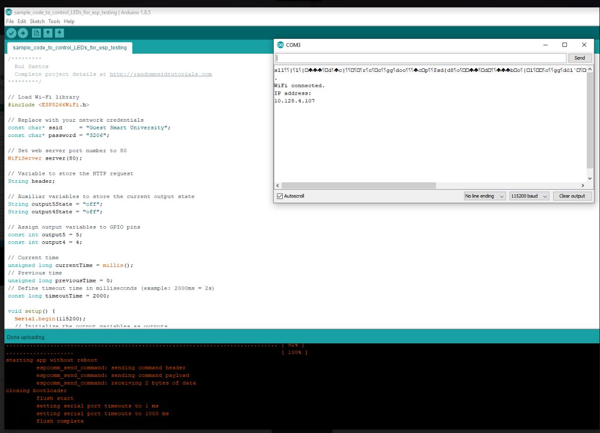
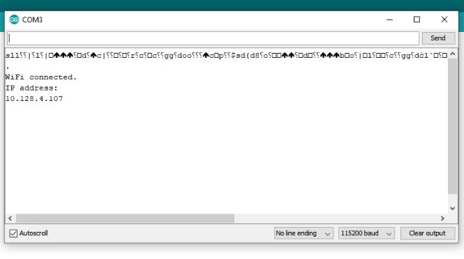
After the upload the code in ESP-Board so I got this IP address.
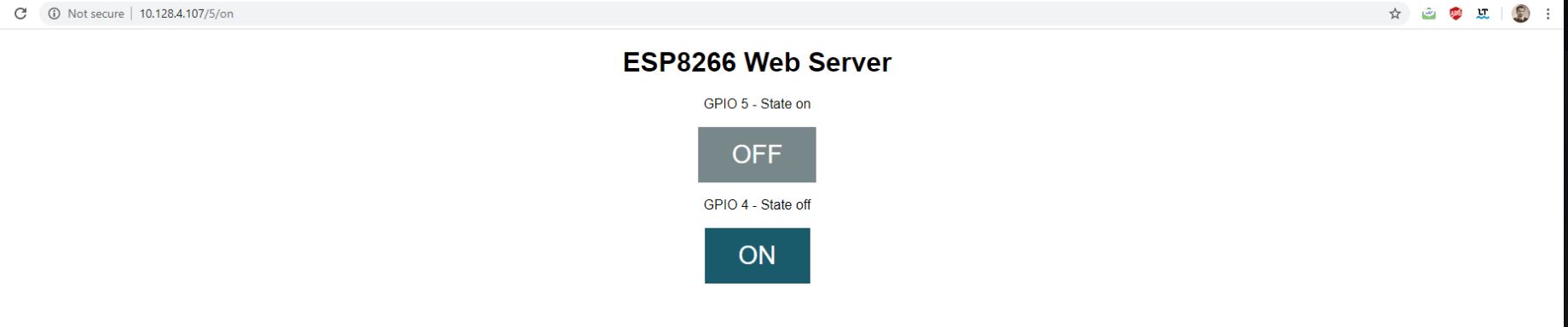
After uploading the code then I got the This IP and copy from here than past on the browser and get this GUI that shows the on and off state.
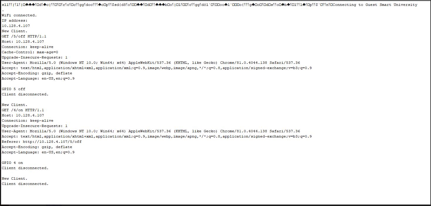
This serial monitor shows results , that when I put the command of the turn of and turn on and its behaviors.
LED Turn On and Off results
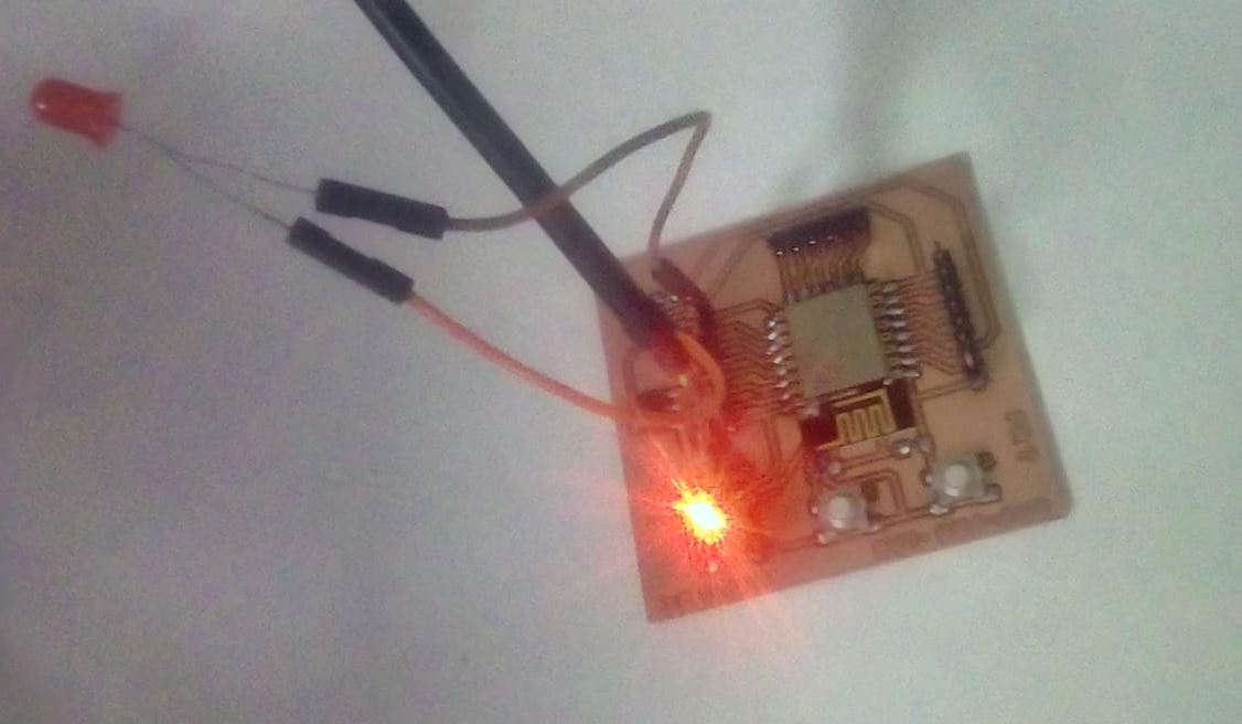
Now when I put the command for LED to on state so result as shown.
Group Assignment
In this week, in group assignment we are working on the I2C communication between two micro controllers, one is Arduino mega 2560 and other is Leonardo Board. We have fellow this this link to implement group assignment. HERE
What is I2C?The I2C communication bus is very popular and broadly used by many electronic devices because it can be easily implemented in many electronic designs which require communication between a master and multiple slave devices or even multiple master devices. The easy implementations comes with the fact that only two wires are required for communication between up to almost 128 (112) devices when using 7 bits addressing and up to almost 1024 (1008) devices when using 10 bits addressing.
Each I2C bus can support up to 112 devices. All devices need to share GND. The speed is around 100 kb/s—not very fast but still respectable and quite useable. It is possible to have more than one master on a bus, but it's really complicated and generally avoided. A lot of sensors use I2C to communicate, typically Inertial Measurement Units, barometers, temperature sensors, and some Sonars. Remember that I2C is not designed for long cable lengths. Depending on the cable type used, 2 m might already cause problems. Connecting more devices If we need to connect more than two devices on an I2C bus, we just have to connect all SDA and SCL lines together. We will need the address of every slave to be addressed from the master Arduino.
ADVANTAGES
DISADVANTAGES
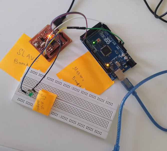
We have connected micro controller, so these steps to connect two Arduinos using I2C:
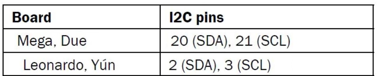
First step Connect pin A4 and pin A5 on one Arduino to At mega 25600 pin 20 SDA , and pin 21 SCL . Second Step the GND line must be common for both Arduinos. Connect it with a jumper. Third Step Remember never to connect 5 V and 3.3 V Arduinos together. It won't hurt the 5V Arduino, but it will certainly annoy its 3.3 V.
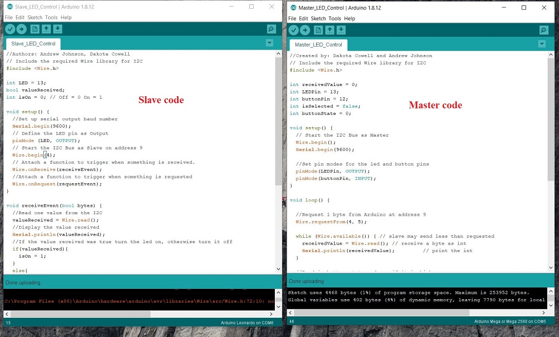
This is the code of master and slave; that is used for the communication I have uploaded the code like master in mega2560 and Salve upload Leonardo.
How It Work
To briefly go through the theory, I2C requires two digital lines: Serial Data Line (SDA) to transfer data and Serial Clock Line (SCL) to keep the clock. Each I2C connection can have one master and multiple slaves. A master can write to slaves and request the slaves to give data, but no slave can directly write to the master or to another slave. Every slave has a unique address on the bus, and the master needs to know the addresses of each slave it wants to access. Now let's go through the code.
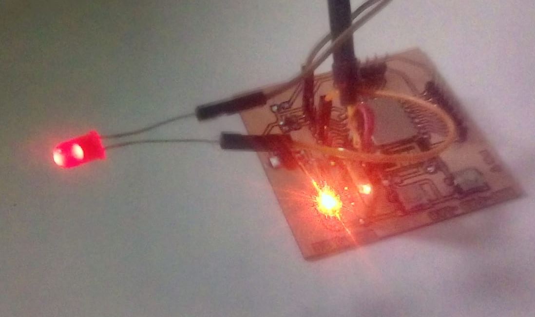
After the uploading the code in the respective board this is the result of our Group assignment in which master sent the command to the slave.bascialy in this assignment, we have considered one microcontroller board as a master board that will command on the other board that is a slave when I am going to press the button of the master board that will start blinking one time and sent the command to slave board for the blinking lED.even we have connected extra led on pin 13 for the blink that shows the communication between master and slave board.
Conculsion
This week we have to learn about the networking and communication design, I have Design the ESP wi-fi Module and Learn about the Communication Protocols. This week is more important for my Final project, I will use the ESP module for communication purposes and very important for the final project for sending and receiving data on Energy Consumptions. In group work we have worked on the I2C communication master and slave between two microcontrollers.one was master that command to the slave to work and the other is slave fellow the command of the master.
Download all files from Here

This work is licensed under a Creative Commons Attribution-NonCommercial-ShareAlike 4.0 International License