Embedded programming 2.0
individual asiignment
Read a microcontroller datasheet and program your board to do something
group assignment
compare the performances and developemnet of diferent workflows
you can go here to see what i did on this week group assignment
i've pushed a test on the final board programmed
Fabacademy 2020 and 2021 efforts
also all of the links can be found under "links and references"
this assignment has various steps
I use a Windows 10 based system the (flashing commands and general workflow of installation may vary for another OS)
for more info about the instalation of edbg and openOCD for to
- Read a datasheet of an MCU
- Design a board.
- Flash the board
- Install the samd11c board on arduino IDE
- Upload a sketch
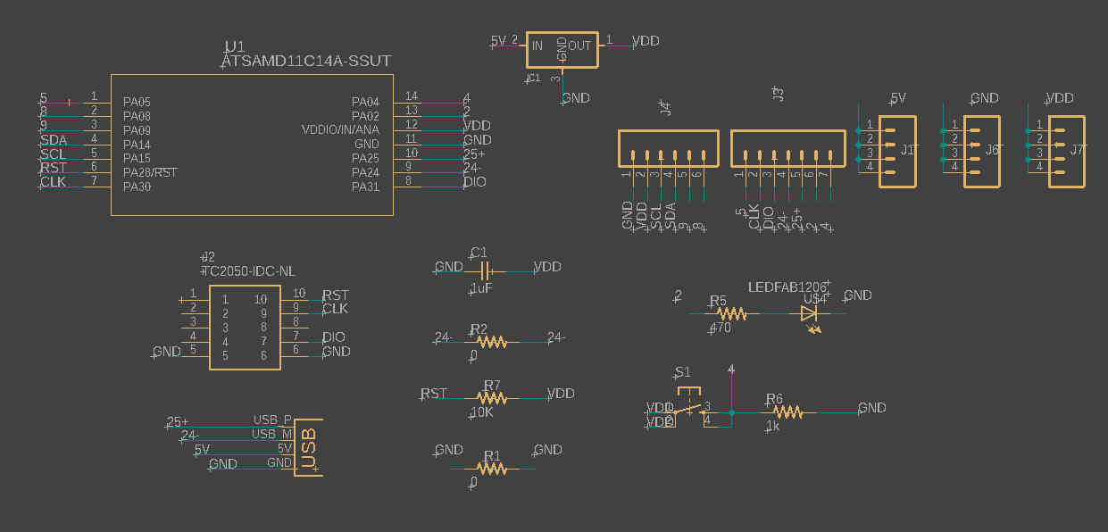
i choose to do my very own version of the samdino made by adrian torres from fablab leon.
i talk more about this design on electronics design week tough.
So i'm up with the task to design and fabricate another homade "arduino" bootleg
so the first on the list was to download the datasheet and try to understand it.
HERE you can download the same datasheet
the first thing i noticed is that has 14 pins
then it has 16KB of flash memory
and unlike the atmega328p i used before this MCU runs on 3.3v.
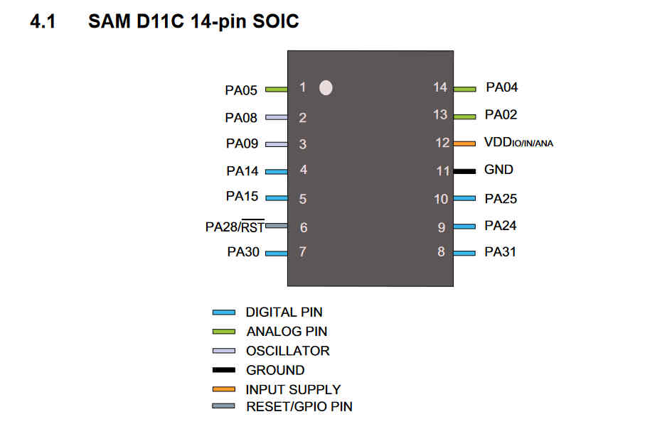
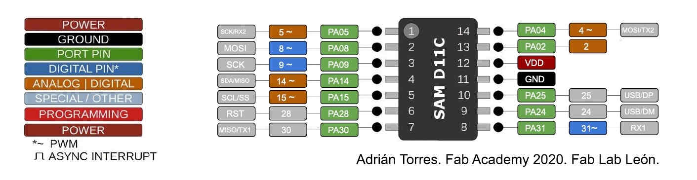
mcu pinout from adrian's samdino page
it has spi,I2C USART comunications protocols compatibility built in
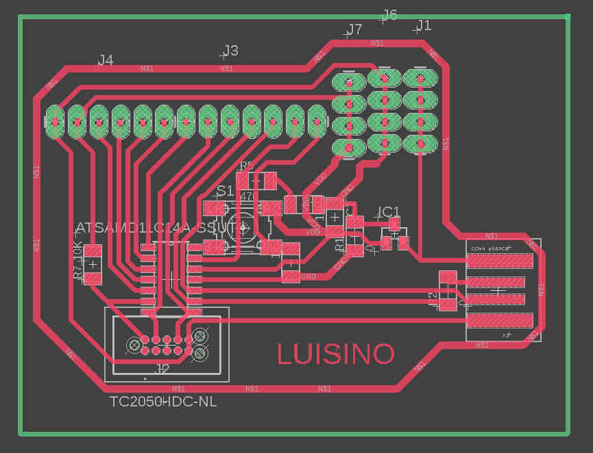
HERE you can check the assignment on electronics design i did
also HERE you can download the EAGlE files on this board
also HERE you can download the EAGlE files on this board
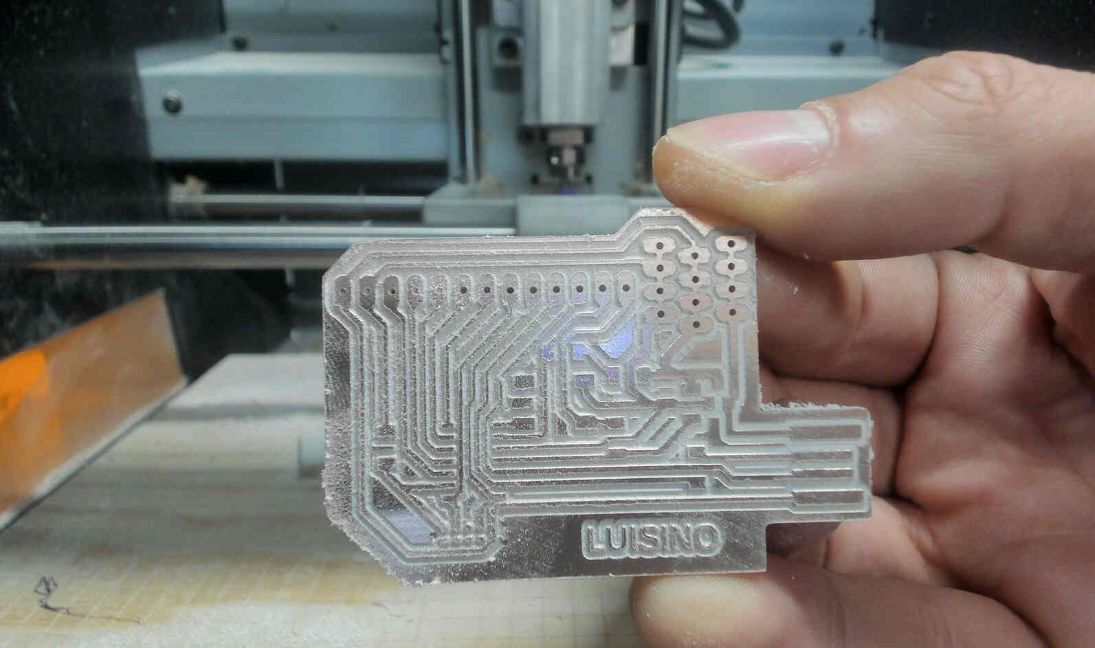
take out the board from the cnc
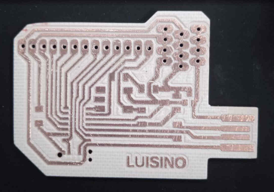
weed it,clean it and probe it with the multimeter
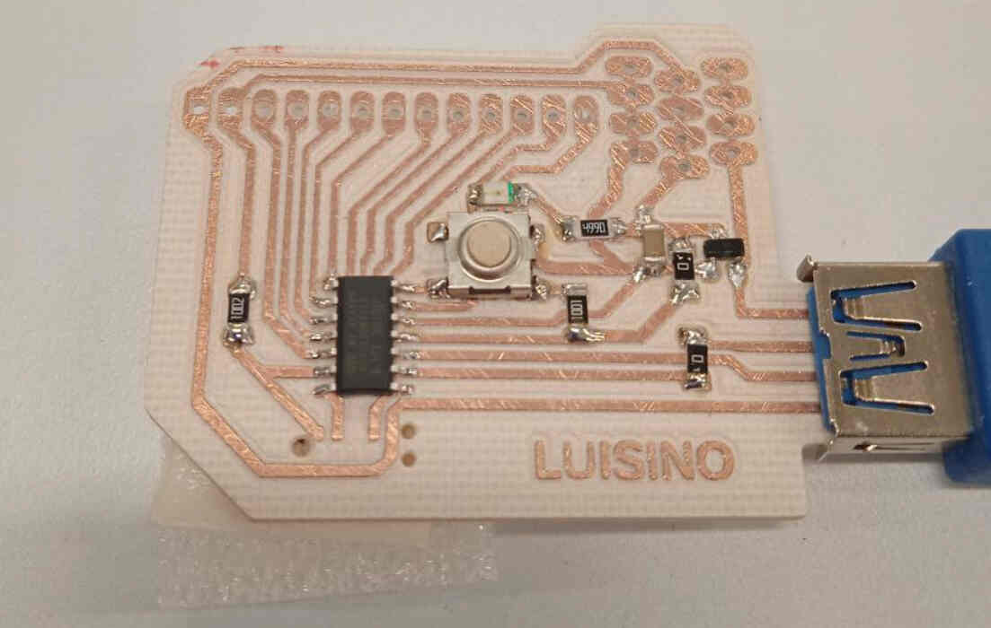
Stuff it and probe it once again with the multimeter
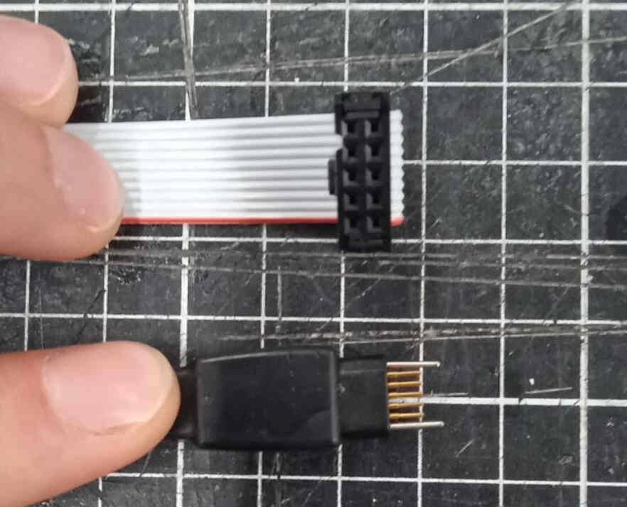
this is the adapter i used to flashe the board
HERE you can check the specs
HERE you can download the eagle footprint to use it on your own designs
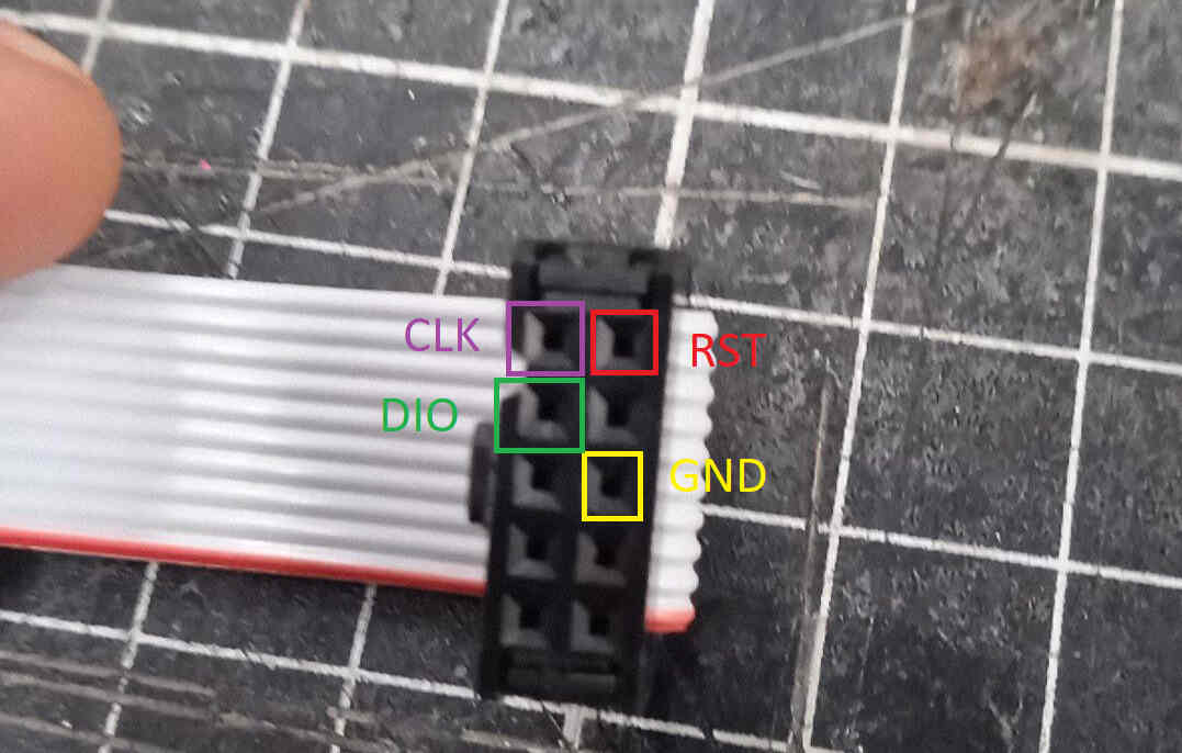
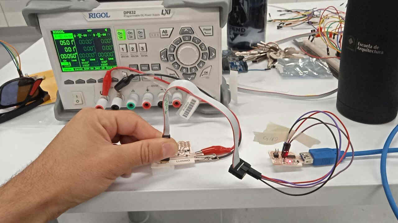
this is how i conected the swd programmer
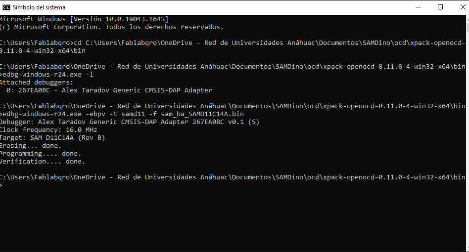
on a fresh windows CMD terminal navigate to the file were the edbg and openocd is stored check electronics production to see how to
download the binary for a generic SAMD11C chip from HERE and place it on the same directory as the edbg,openocd and free-dap binary file
and then type edbg-windows-r24.exe -ebpv -t samd11 -f sam_ba_SAMD11C14A.bin
https://www.mattairtech.com/software/arduino/package_MattairTech_index.json
you need to copy this URL and paste it on the arduino IDE
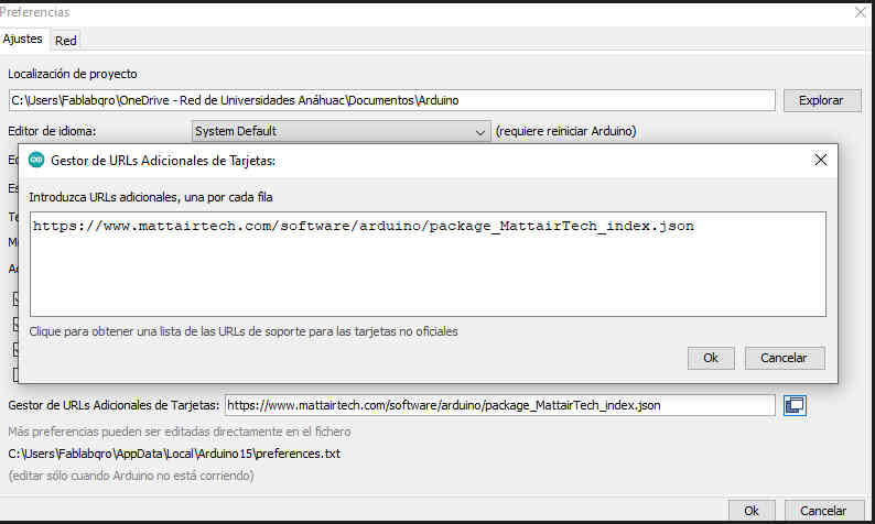
You can do it under file/preferences
Only then you'll be able to install the MattairTech core boards
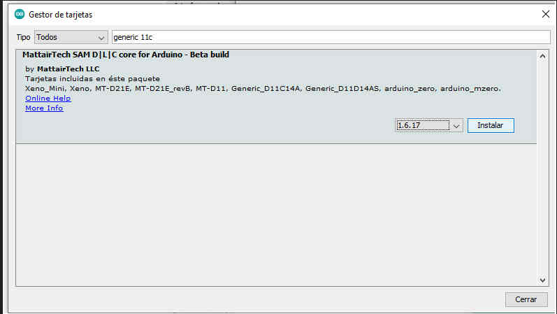
you can do it under tools/board/board manager
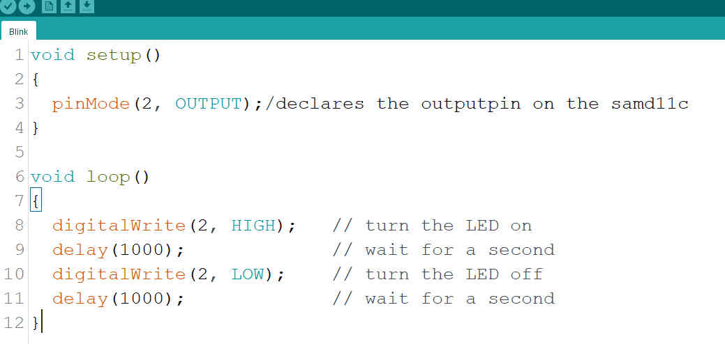
open the blink example and use it to turn on/off the led on digital pin 2
HERE you can download my sketch
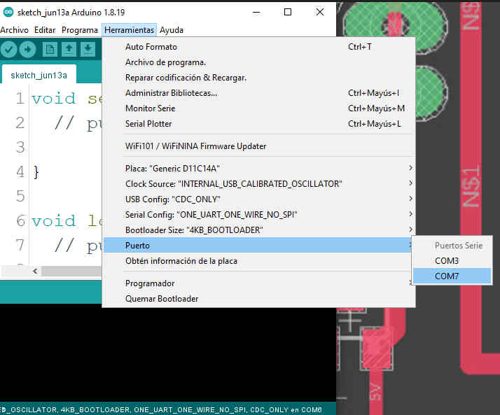
Select you com port before you upload the sketch
on the lower half of the IDE GUI you should get a message like this one
Also i did a button testing on this week
HEREas always you can get the file .ino from here or in the "links and reference" section
this is a simple counter and push button and a LED just to test the board
Morse code test

this picture i took it from a tutorial HERE
the article does not authors a person but an "editorial team"
so this is an excelent resource to find diferent code examples and well explained.
i'll try my best to explain how it works on the comments of the .txt and .ino files
so this is a sketch to translate serial monitor into morse code using a buzzer
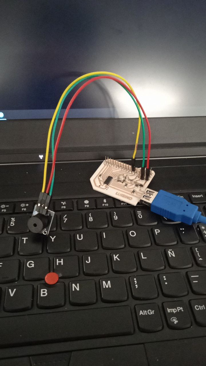
just 3 wires 5v, gnd and signal comming from pin 2 on my board
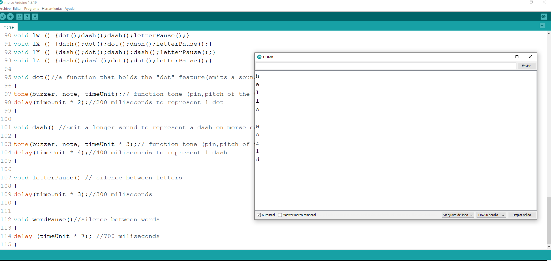
for this code i use one pin as output(specifically pin 2 on my board).
i use a variable to set the default tone of the buzzer (1000)
because i'm only using nested IF statements and functions. i do not need to call for any library
if (input == 'a' || input == 'A') if the variable holds the char "a" or "A" then calls the function 1A()
then the function 1A() it's called later outside the void loop
within void 1A() and it calls specific function in a specific order to make the letter
for the example of the caracter A or a
it is dot followed by a dash and then a letter pause
then after the tone the delay of the time unit that represent the letter pause
also all of the lines are commented on the text file below.
everything that follows after // is a comment and is just for debugging purpouses
Conclusions
i would never have done it with out adrian's documentation.