Final project
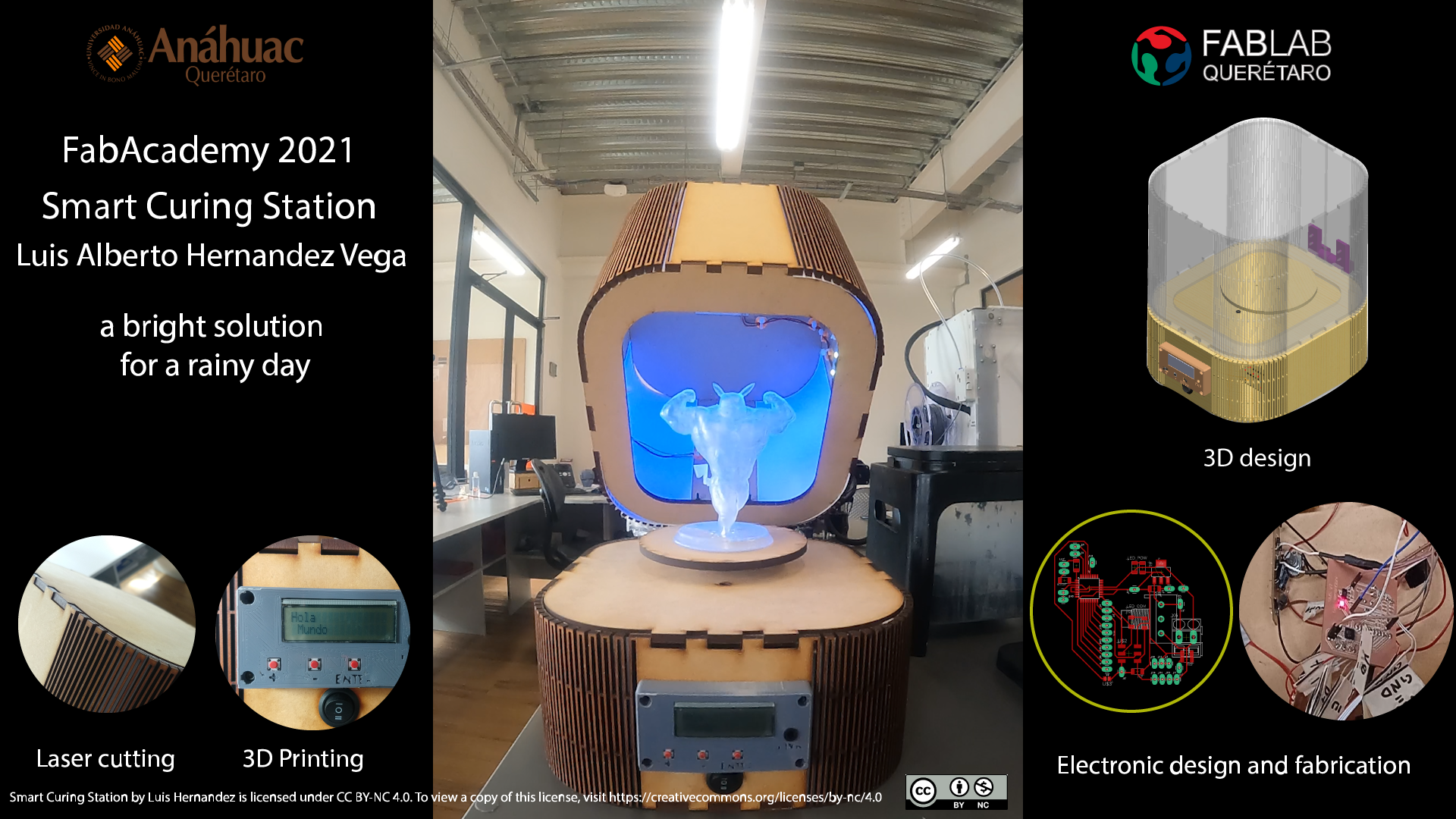
SMART CURING STATION
why change to another final project?
Due to the COVID 19 contingency we've been quarantined since mid march of 2020 in Mexico (yes, a little back in comparison with other countries).
so in my country we have been isolated from our Labs since week 7 (computer controlled machining) of fabacademy.
HERE you can learn about what i did during COVID-19 outbreak.
and probably will continue until mid june or early july.
having this picture in my head i try to use what we can have at hand at our labs for use.
my previous idea required me to purchase a barcode reader or a QR reader as well as a wifi module for comunication to the device.
but since borders are closed and all of those accesories must be imported to my country. I tought to implement the plan B.
It's a lot simpler but i think i has a lot of didactical value.
what is it?
at FabLab Querétaro we have a Form 2 SLA printer.
Ocasionally by the time the printing it's done is dark or it's really cloudy.
So, i have being studying the subject and found some really cleaver DIY projects on youtube to cure resin based prints using UV lights. But. they all look handy but it's just a UV light bulb wired to a power cord, a switch and the housing is a metallic bucket cover in aluminum foil or other reflective tape. they jus place them on top of the piece or put it inside and put a cap or something.
That's where the smart curing station can be handy.
As a fabLab we can use our knowledge and skills in digital fabrication and make a process or product better.
Resuming. It's just a way to cure the prints on SLA printers with out taking them out when there's no sun.
here i just going to post the image for the plan development but i've created an entire page dedicated to the wins and fails while creating this project it's called Week 18: project development
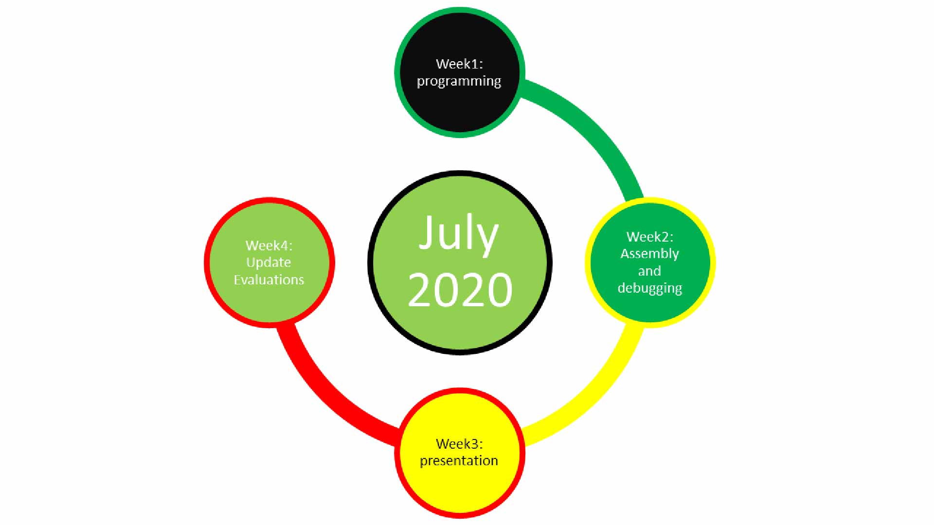
this is the general plan for this last month before closure on the fabacademy 2020
due to covid i did not had the time to finish in time
since then i've been working on my final project and here i will leave al the information about it
INDEX
- BOM
- CAD
- One wire Diagram
- Electronic design
- Soldering
- Programming
- Assembly
- Slide
- Video
- Links and references
All of the files will be at the end of this update under Links and references.
Since the Begining of this Fabacademy 2020 i came with diferent versions of each chassis,Mainboard,ButtonPad,power supply and Hinges.
BOM
Back to index
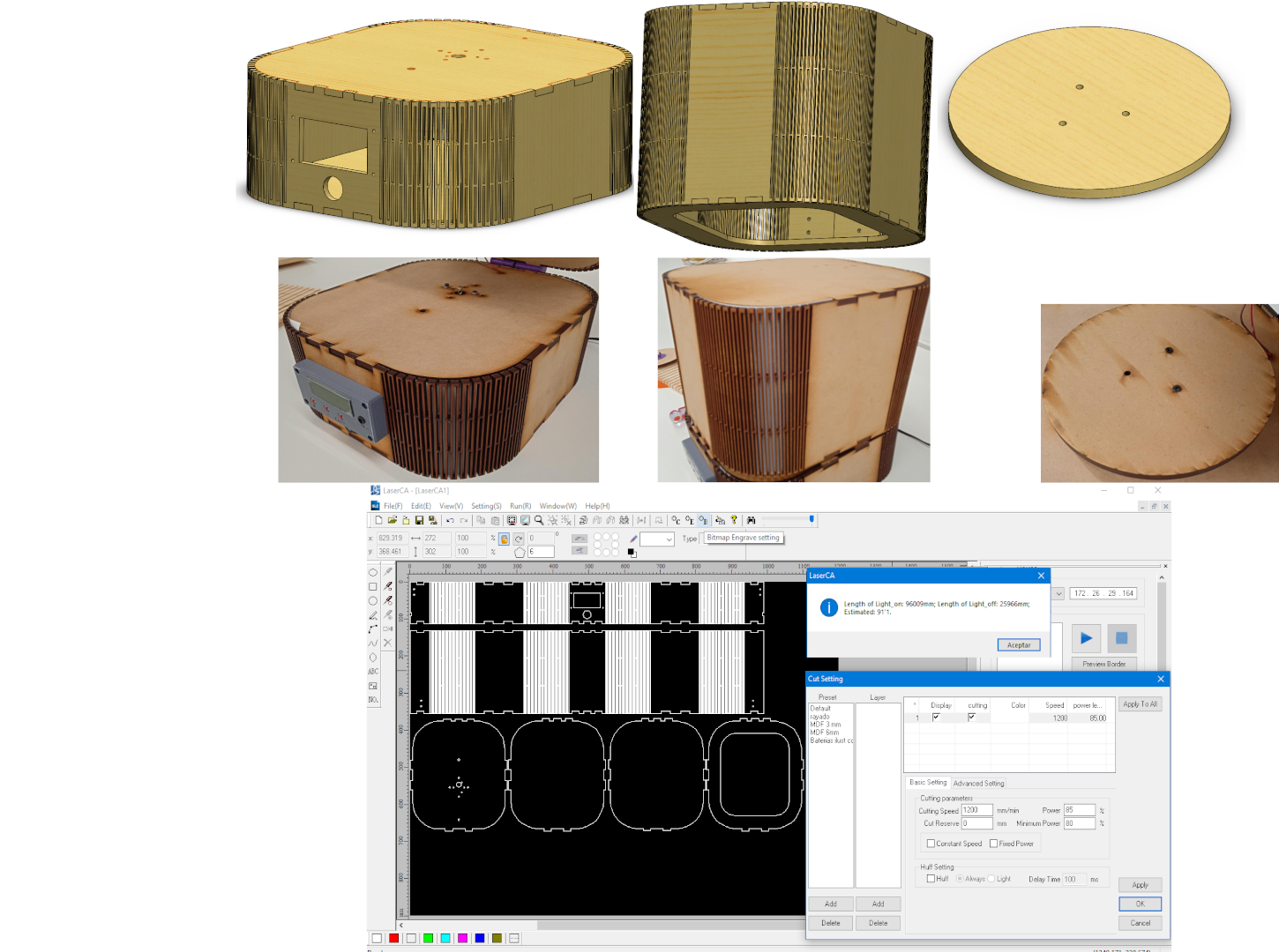
CAD
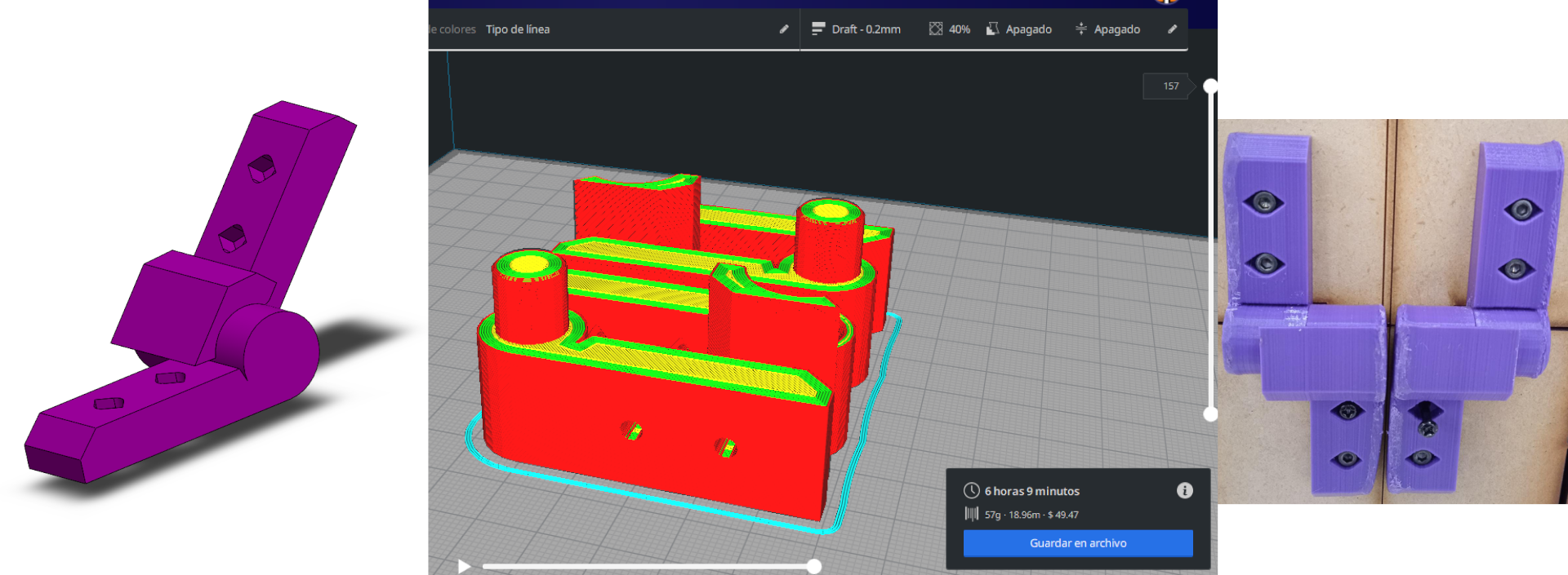
picture of the design of hinges
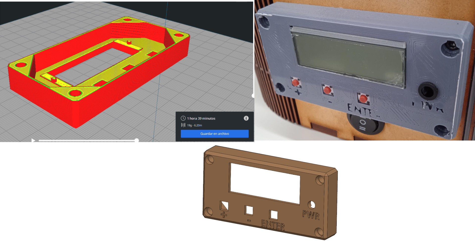
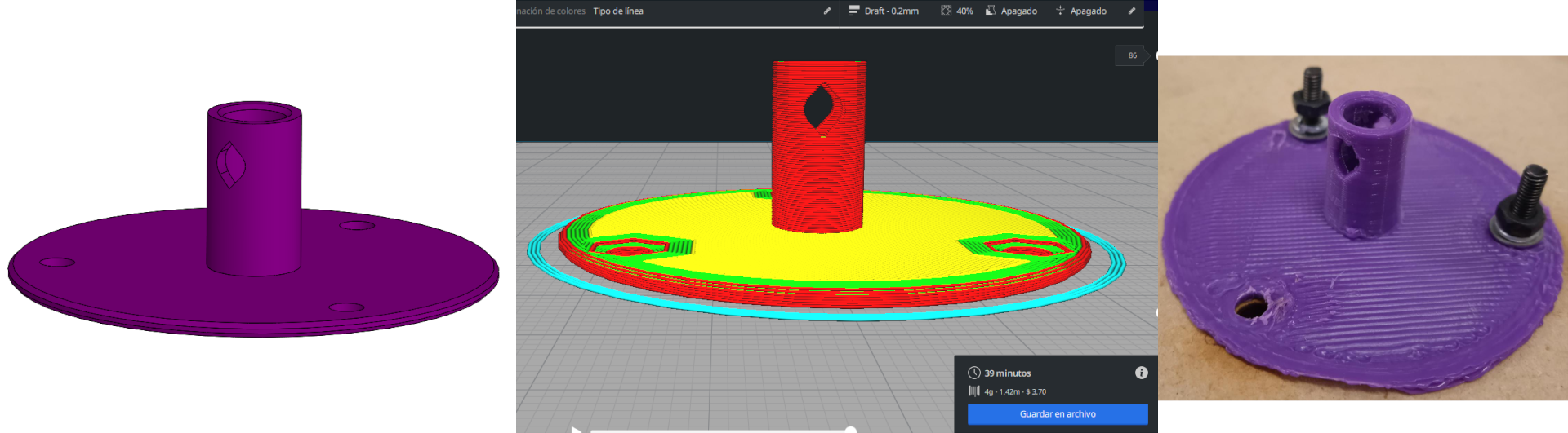
picture of the design of the Housing for de LCD and the button pad
picture of the design of the coupler fot the shaft and the turnable
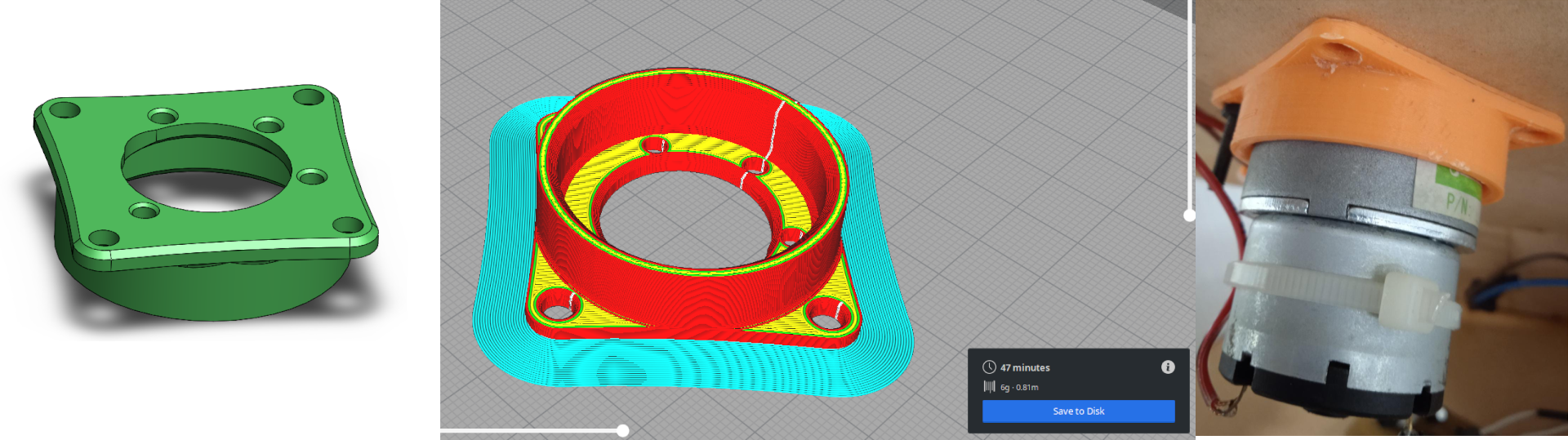
picture of the design of the motor bracket
Back to indexOne Wire diagram
as an advice of my global instructor luis
i did a diagram on how the project works
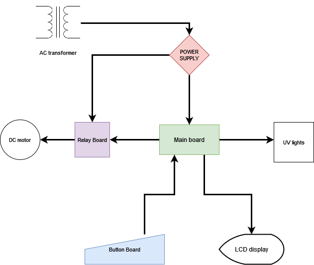
then the board turn on and off the relay board and the UV light modules
Electronic design
Since i have designed my own power supply i had to develop it so i used autodesk EAGLE.
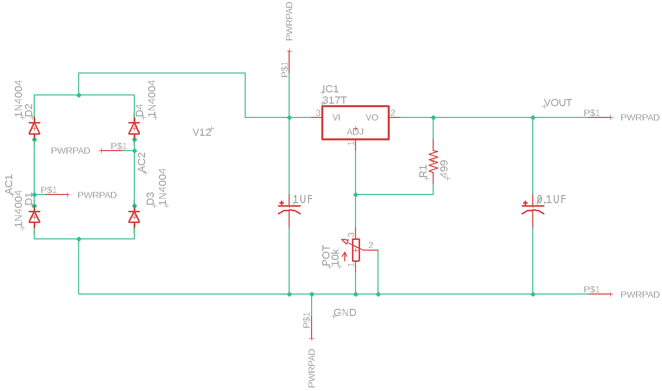
this is a screenshot of the schematic i build for the power supply
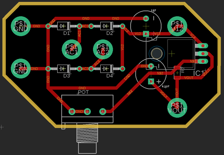
this is a screenshot of the board file i build for the power supply
all the fabrication files you can download them on the links at the end of the page
i made my own button pad board for the case where i wanted the controls to be on my design
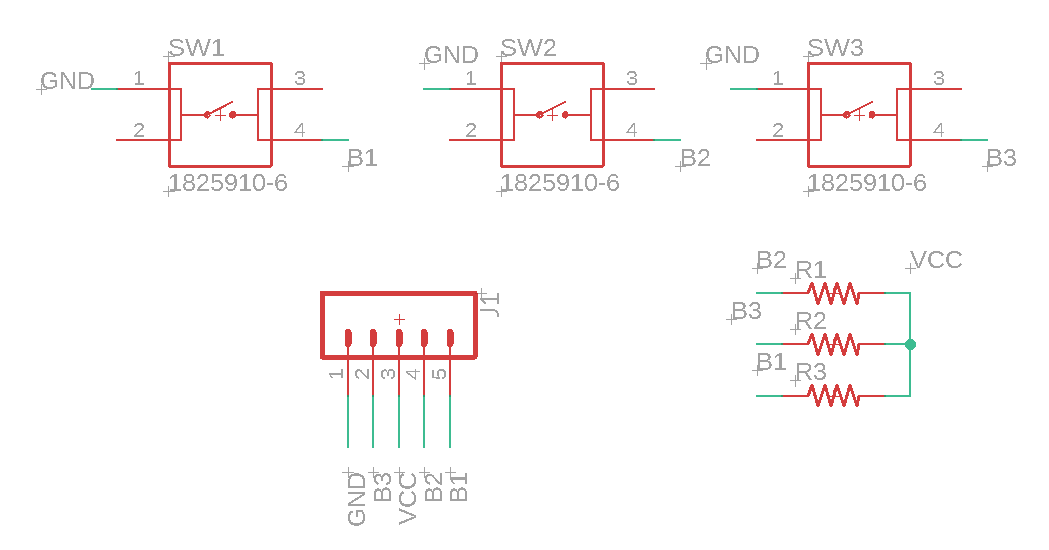
this is a screenshot of the schematic i build for the button pad
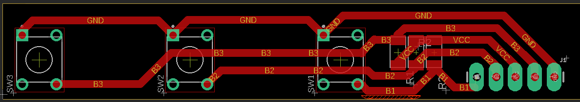
this is a screenshot of the board file i build for the button pad
all the fabrication files you can download them on the links at the end of the page
i also designed a modular board for a 5 dc volt relay i had in order to draw the current for the motor directly from the power supply
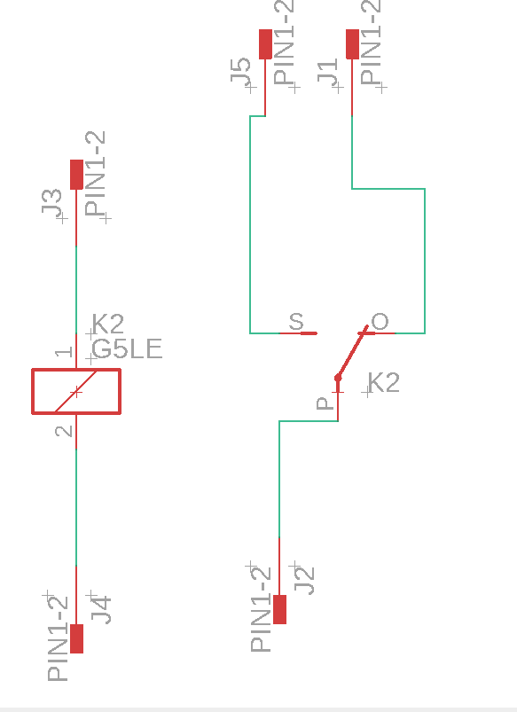
this is a screenshot of the schematic i build for the relay
this is a screenshot of the board file i build for the relay
all the fabrication files you can download them on the links at the end of the page
finally for the main board i used a ATMEGA328P (TQFP package) because i decided to use an LCD display without the I2C adapter and the number of pins needed for the display would not be sufficient with the attiny's we have in our lab.
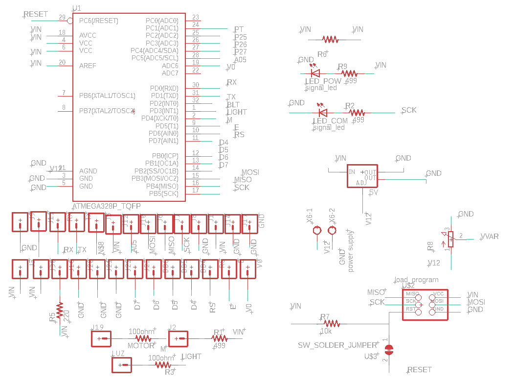
this is a screenshot of the schematic i build for the main board
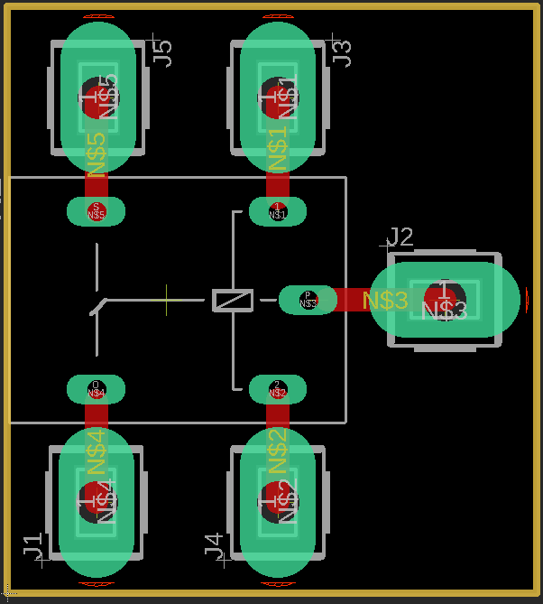
this is a screenshot of the board file i build for the main board
all the fabrication files you can download them on the links at the end of the page
soldering and fabrication
here i will push some pictures of the proceess of fabrication of the main board but i aparently i did not have any of the power supply and the button pad.
this is a quick vid on the milling working
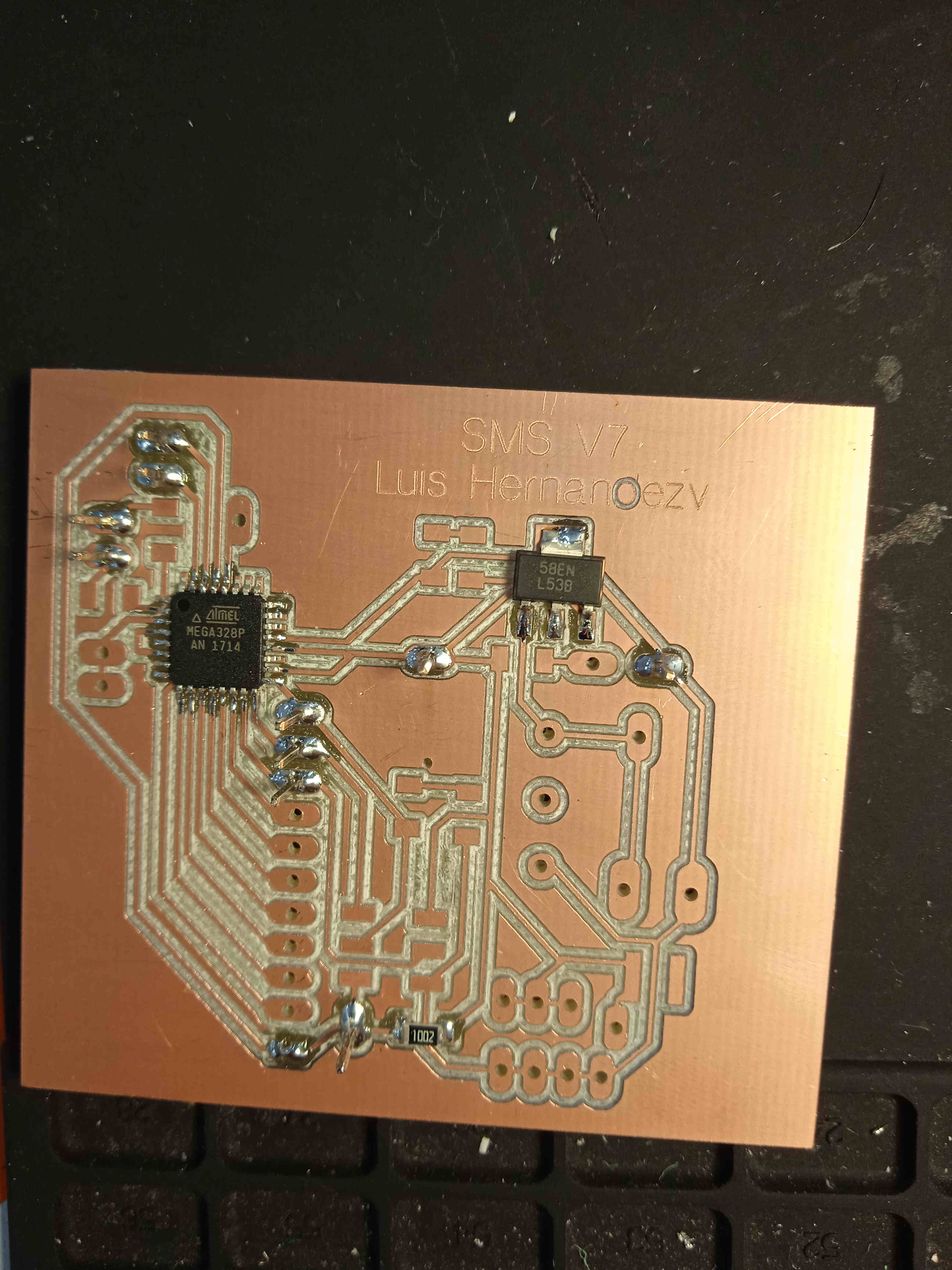
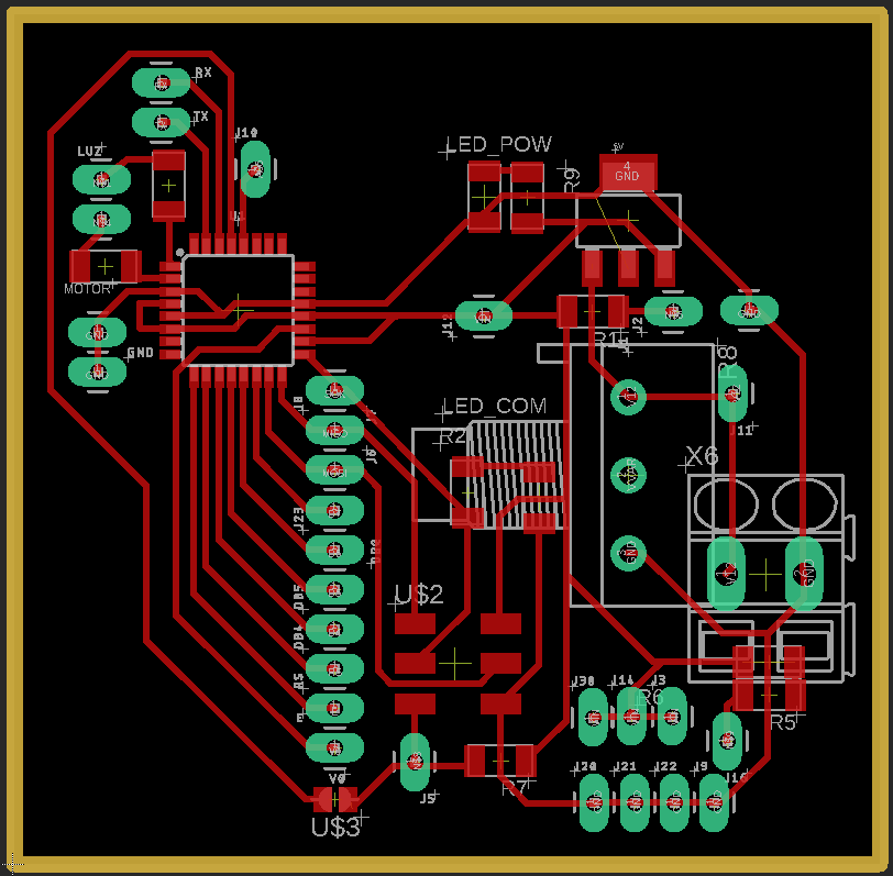
this is a picture of the main board just finished.
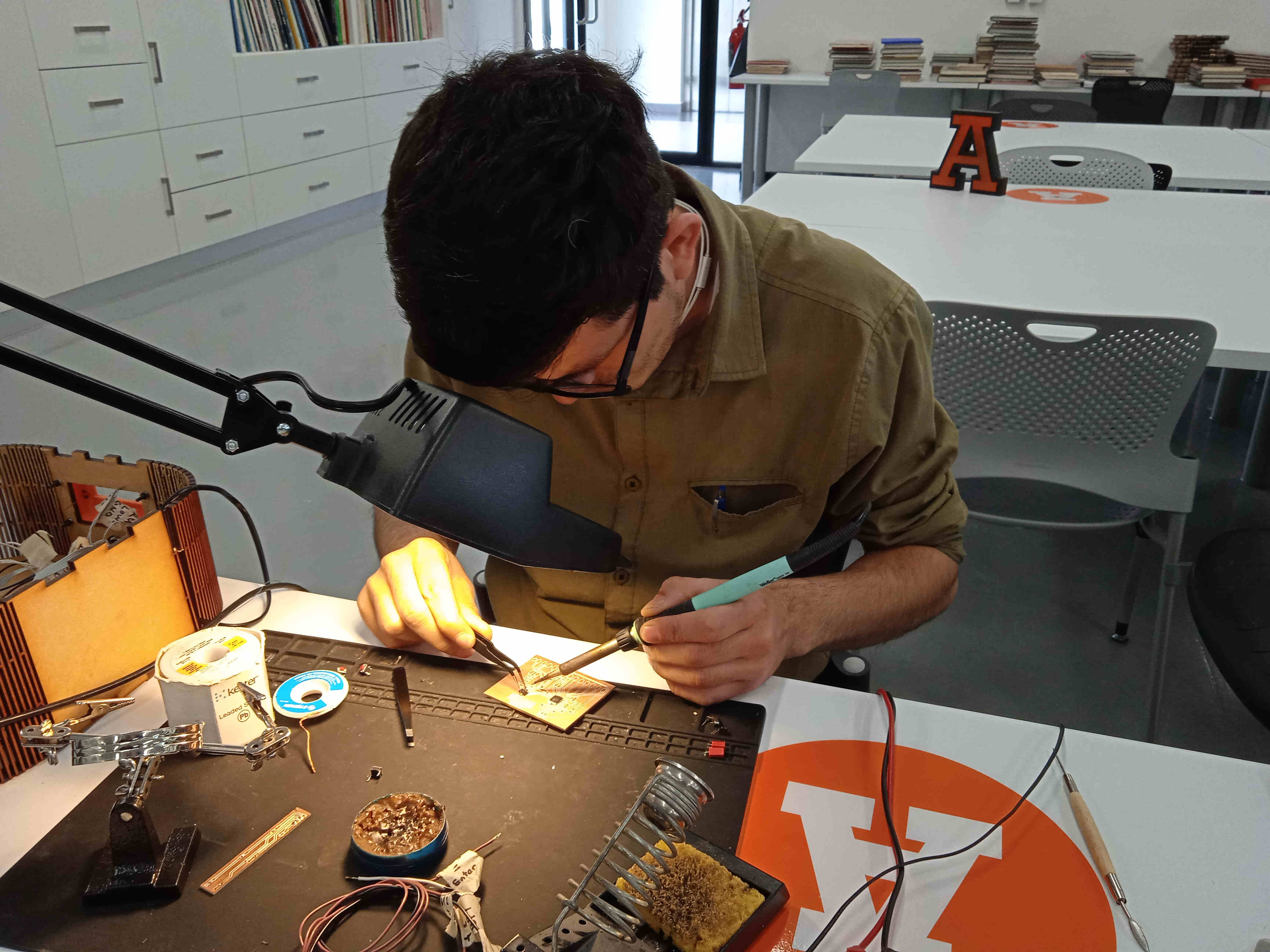
i had to develop patience and a steady hand for the soldering skill.
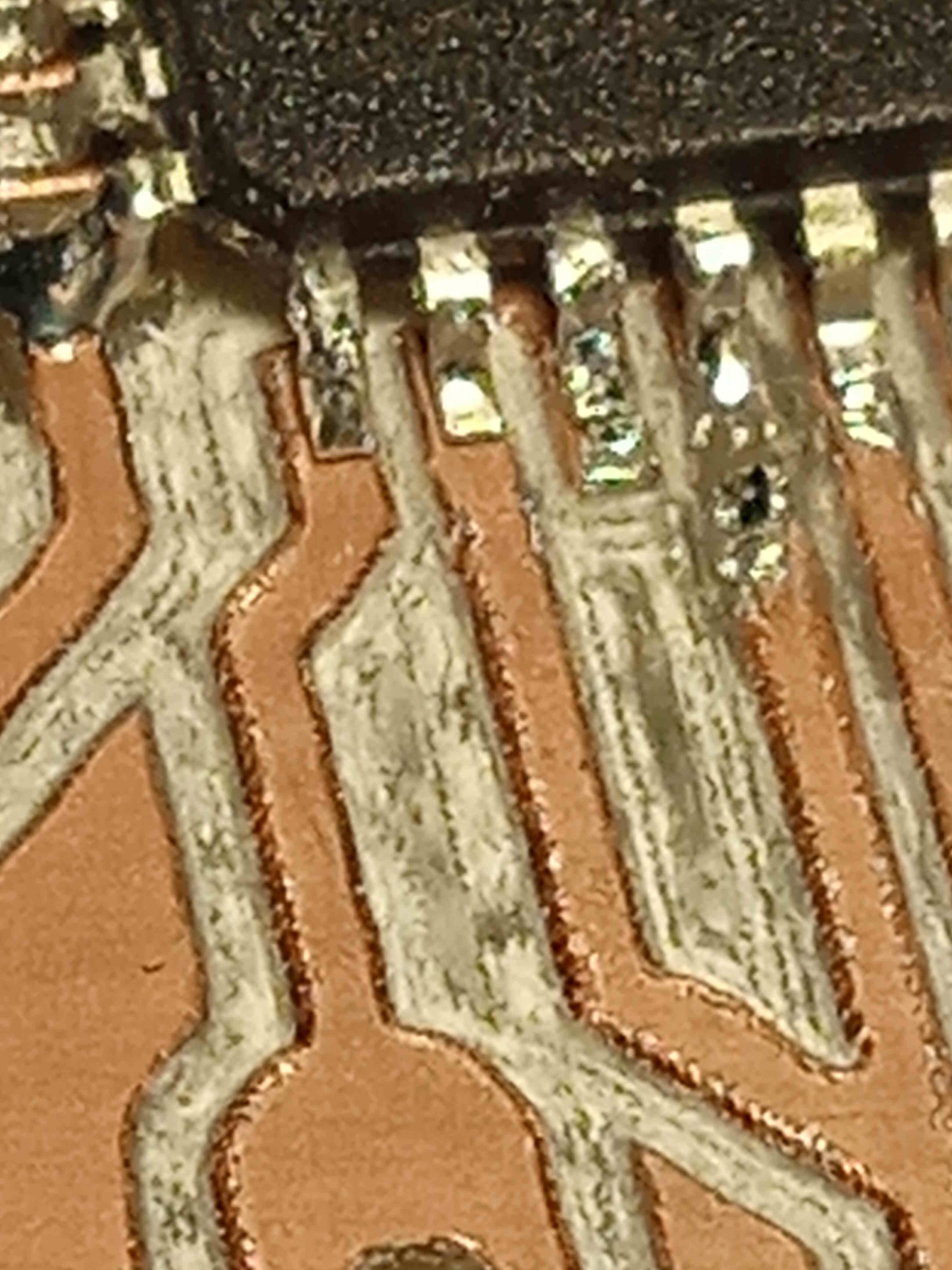
i'm really proud of this board because i did not made a soldering bridge.
all the fabrication files you can download them on the links at the end of the page
programming
here i'm going to push some pictures about the program currently running on the main board.
as inputs i've made a custom button pad to fit my housing.
as output i choose a gear box dc motor, a LCD display and off course the UV LED ligths.
since i'm not a programmer i could sa that this was the part i strugled the most.
this is an iframe of my program. i used arduino IDE as my develop interface. since i'm using the ATMEGA328P running with the internal clock at 8 MHz.
after burning the bootloader of the microcontroller i went ahead and upload a blink skectch using just another pin on the board since i've already attached the UV lights on the board.
this is the video on the modified blink
after that sketch i had some trouble due to my wiring. So i had to spend a day and a half dealing with the wires.
this is a video on the test of the program.
assembly
here i should explain my desings components and materials
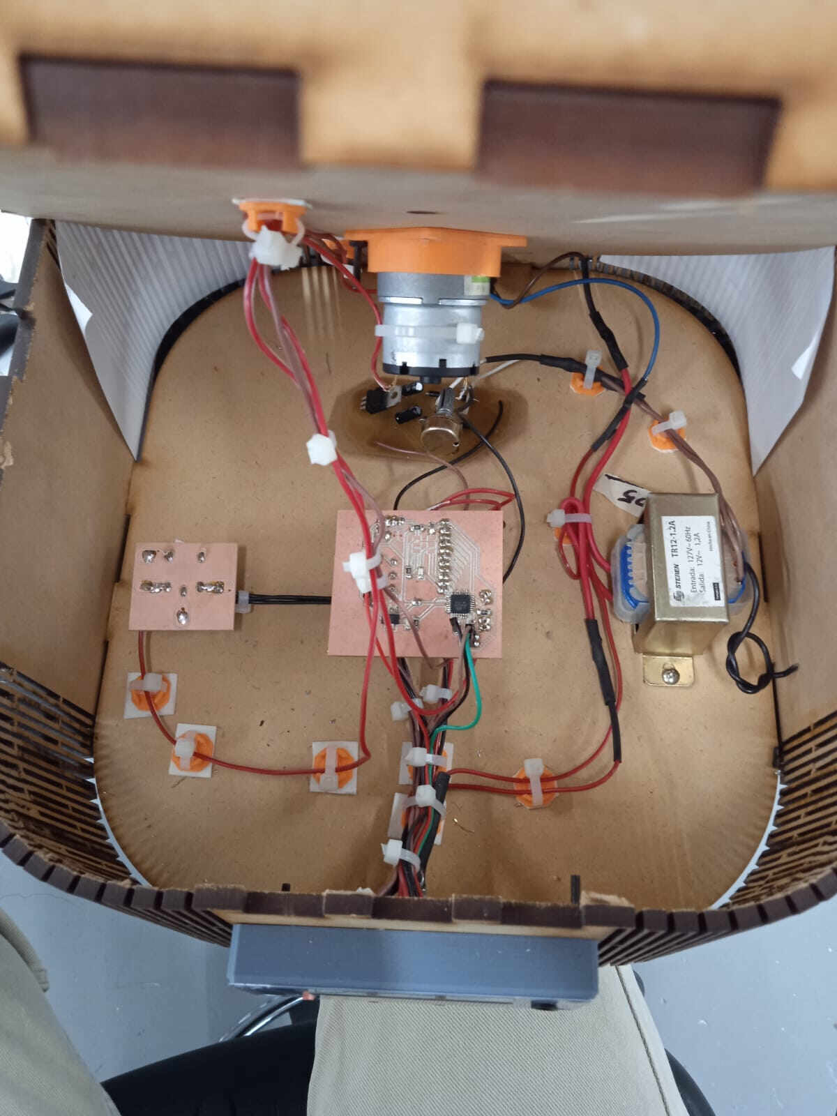
this is a picture of the inside of the beast.
finally all wired uphere you can download the list of materials and the reference links from where i bought them.
slide
finally this is the final slide for my final project. obviously i'm not a genious on using illustrator but here's what i came with.
in this image i explain briefly just the things that i used on the modules of the FabAcademy.
video
just as you can see in the video i'm not very proficient in the use of my video editing skills and i had to turn down the quality of the video just to make it under 10MB to meet the requiremnts on the assingment.
this is just the video on the use of the smart curing station.
Links and refences
here i'll drop some information i used during the develop of the final project
documents
CAD
native 2019 solidworks files.part1
native 2019 solidworks files.part2
native 2019 solidworks files.part3
Eagle board and schematic files
CAM
milling parameters for the roland files
here you can donwload that awsome pikachu model i used in the final presentation video by cyenyee page on thingiverse.
hereyou can check out the youtube channel of "el profe garcia" an awesome resource for electronics and programming in spanish language.
hereyou can check out the youtube channel of "Profe Pablo" an awesome resource for electronics and programming in spanish language.
hereyou can see how i managed to burn the bootloader without the external oscilator.
hereyou can check out my personal youtube chanel where i pretend to be uploading content about digital fabrication. basic topics of electronics and basic programming.
Acknowledgment
Since i've used some methods i've found online i want to acknowledge some of the creators of the online content i've used some of the sources are in spanish since that's my native language and it was easier for me to learn complex topics as programming.
Thanks
Finally i want to say thanks to all the people that walked with me (in one way or another) in this journey.
Smart Curing Station by Luis Hernandez VegaCC BY-NC 4.0

