10. Input Devices
individual assignment:
      measure something: add a sensor to a microcontroller board
      that you have designed and read it
   group assignment:
      probe an input device's analog levels and digital signals
Creating the board
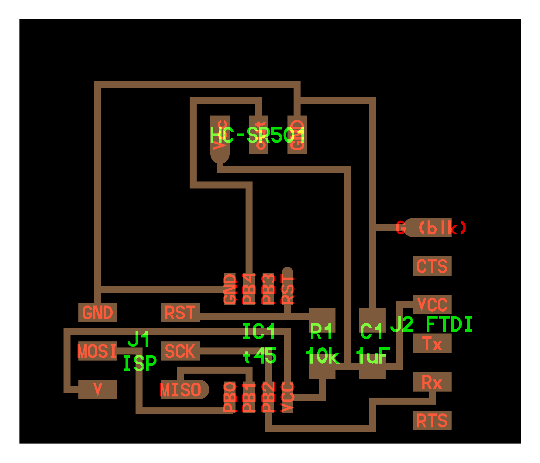
I decided to create a board that gets input from a pyroelectric sensor, most specifically the HC-SR501. However, instead of using the old ATTiny45 chips, I decided to switch over to the never ATTiny412 chips as programming them were more familiar and I already had the resources available. Using Neil Gershenfeld’s board, I replaced the MCU and added in an LED.
Using EagleCad, I designed the board and sent the file to my instructors to get it milled out.


The PIR sensor that I will be using, has three pins for VCC, Out, and Ground. To mount this onto my board, I unsoldered the three pins and replaced them with right angle SMD pins.


I then soldered all the components onto my board.

However, upon closer inspection, the PIR sensor had VCC and Ground opposite to the pins on my board. I further realized that EagleCAD rotated my three pin when I switched over to a board and I did not realize this. Thus instead, I put a three pin on my board and used jumper wires to hook up the right connections to the PIR sensor.

Programming the Board
I will be using the Arduino IDE to upload code to my board for convenience.
Now, the PIR sensor doesn’t input anything special to one of the ports on my ATTiny412. It is exactly similar to a button press, meaning that I could use the button code that I used for last week.
Here is how it looked:
I was suprised about how far it could detect motion at. Its maximum range was a couple of meters away, enough to cover half or even an entire room.
Now, it was time to get my board to also do some serial communication. I wanted to get the ATTiny412 to tell me whenever motion was detected and ask whether or not I wanted the LED to blink. I used bits and pieces from the echo hello-world boards we made on the electronics design week to help give me pointers on how to do so.


Finally, I wanted a little GUI to display whether motion was being detected, similar to Neil Gershenfeld’s video of his pyroelectric board. Thus, I used Python along with the PySerial and PyGame packages. PySerial allowed Python to recieve serial communication and PyGame was what I used to create the GUI. My code simply created a window that stayed green when motion was undetected along with displaying the words, “Motion Undetected”, and would become red when motion was detected.
Here is the code:
import pygame
import serial

pygame.init()

screen = pygame.display.set_mode([500,500])

font = pygame.font.SysFont("arial", 20)

while True:
    try:
        ser = serial.Serial("COM8", 115200)
        text = font.render("Motion Detected", True, (0, 0, 0))
    except:
        if ser.readline().strip().decode("utf-8") == "Motion Detected":
            screen.fill((255, 0, 0))
            text = font.render("Motion Detected", True, (0, 0, 0))
        else:
            screen.fill((0,255,0))
            text = font.render("Motion Undetected", True, (0, 0, 0))
    screen.blit(text,(250 - text.get_width() // 2, 250 - text.get_height() // 2))
    pygame.display.flip()

pygame.quit()
Here it is in action:
Here are my files for this week: download
Creating a Hall Effect Sensor board
For my final project, I needed to implement a hall effect sensor so this was the perfect week to experiment with the hall effect sensor and get familiar with it. I looked to Neil’s board for guidance on how to wire up the Hall Effect sensor and I added an LED for future use. Here is my final schematic and board:


I got the board milled out and here it is before and after soldering:


Programming the Board
Get an input from the Hall Effect sensor was simple. I did an Analog Read on the Pin Out for the Hall Effect Sensor to read the Voltage it was outputting.

The highest value it seemed it could output was a little over a 1000 and the lowest was almost near zero. I achieved these by holding a neodymium magnet as close as possible and changing which side of the magnet I was using. Using this, I crafted another GUI for my Hall Effect sensor to better visualize the output of the sensor. This is what it looked like:
However, I realize that here was a big of lag between when I changed the position of the magnet and the GUI updating. I fixed this by decreasing the baud rate to 9600 instead of the 115200 I had been using before. Now, my GUI was working perfectly and I was ready to use this for my final project. Here is the final product:
../images/week10/BaudRate9600.jpg)
Here are the files for this week: download
This Hall Effect Sensor board will be useful in my final project due to the Brushless DC Motor not being able to accurately spin at a certain RPM. Thus meaning that I will need a method to measure the delay between each rotation of the LED blades. This is where the Hall Effec Sensor comes into play. I will have a neodymium magnet in the path of the LED blade, and a hall effect sensor will be placed on the LED blade so that in every rotation, the sensor will pass the magnet. Every maybe 5 passes, the hall effect sensor will measure the time it takes for the LED blade to rotate and this delay will be sent to the master board in order to guide the delay of the LED blades.
Group Project
The group assignment can be found here.