Final Project
Throughout my FabAcademy experience, the desire to create a project incorporating Persistence of Vision has been unwavering and will definitely be incoporated into my project.
Slide/Video:
Planning and Research
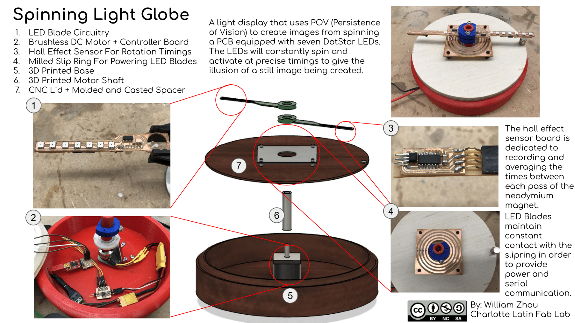
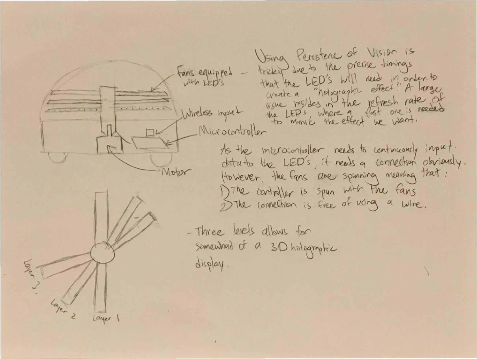
My Final Project will use three rows of fins equipped with fast refresh rate RGB LEDs. Having three rows will allow me to create a 3D hologram like effect. However, only certain LEDs have a fast refresh rate. Dotstar LEDs from Adafruit have fast data and PWM rates suitable for displays such as the one I will be creating. Either I will receive communication from a computer or use master and slave communication to give information to the LEDs on my project.
2D and 3D Modeling
Here is a sketch I created for my project:
Here is a 3D model of my final project that I created in Fusion 360:
Materials
Here is a table of most of the components needed for my final project:
| Component | # of Parts | Cost |
|---|---|---|
| Brushless DC Motor | 1 | ~$30 |
| Electronic Speed Controller | 1 | ~$15 |
| Dotstar SMD LED | 20-30 | ~$15 |
| ATTiny412 | 3 | $1.35 |
| ATMega328p | 1 | $2.56 |
| A1324LLHLT-T (Hall Sensor) | 1 | $2.20 |
| 1/8in Plywood Sheet | 1 | ~$3 |
| Single Sided FR-1 | 4 | $4 |
| Neodymium Magnet | 1 | $1.33 |
Inspiration
Inspiration was gathered from a project developed by Maximilian Mali named voluMen:
My final project will be simpler and easier to fab.
Chosen Licence
In week 13, the license I chose for my project is the Creative-Commons Attribution Noncommercial Share-Alike license. This means that people can use my work, but they have to credit me fully, they cant use my work to make money, and they have to licence any work they do off of mine under the exact same license.
Final Project Documentation
Brushless DC Motor
For my Brushless DC motor, I needed to fabricate a board that could send PWM values to an ESC hooked up to a motor. The board design was relatively simple. It included an Attiny412 with FTDI pins, two pins for UPDI programming and three more pins for the ESC. One of these pins would be connected a port on the Attiny and another one of the pins would be connected to Ground. The last pin does not need a connection and I only included it to fill up all the pins. This is a diagram of the needed connections for my board:

Here is the schematic and board I created to match up the connections. I added an LED in the design so that I could test if the MCU on the board still worked or do other things such as blinking the LED when I send a new PWM value to the Attiny.


Now for connecting my board to the ESC and Motor, I found a very simple diagram for the correct connections. I simply changed the pin number for the Arduino Uno to the pins I used on the Attiny412.


Now with the hardware side done, this guide gives a tutorial on interfacing an arduino with a brushless dc motor. Since ESCs use the same type of control signal as a servo, we can simply reuse Arduino’s dedicated library for a servo to instead control an ESC. We can see the similarities between these two motors in this diagram:
Instead of a writing an angle to the BrushlessDCMotor, I figured it would be better if I instead wrote the microsecond delay between each pulse where the lowest delay would be 1ms and the highest 2ms. This is the code I used:
#include <Servo.h>
Servo ESC;
int pwm = 1000;

void setup() {
    Serial.begin(9600);
    ESC.attach(4);
}

void loop() {
    if (Serial.available()) {
        pwm = Serial.parseInt();
    }
    ESC.writeMicroseconds(pwm);
    Serial.print("uS = ");
    Serial.println(pwm);
}
However, when using this Brushless DC Motor, lots of beeping would happen when putting in any number and it seemed that I could not go lower than any number I first put into my motor. Dr. Harris, one of my FabAcademy instructors, brought up the idea that I may need to calibrate my Brushless DC Motor and found a GitHub page of someone that wrote a dedicated sketch for just that. I was more interested in how it worked rather than using the actual sketch as I already had code.
In their page, the author perfectly describes the steps in calibrating your ESC using an Arduino. Here is a summary of the steps:
- Without the ESC powered, send max throttle to the ESC by writing a ms of 2 to the ESC. This will make it enter programming mode.
- Power up your ESCs. A series of three beeps will occur to say that the power supply is okay.
- Now send the min throttle to the ESC by writing a ms of 1 to the ESC.
- Your ESC should now be calibrated!
After my ESC was calibrated, the BLDC motor worked fine and responded to our actions even if power was removed and plugged back in.
Base
With the Brushless DC Motor also came a mount that I integrated into the design of my final project’s base. Here is what the mount looked like:

After measuring the dimensions of the holes, I CAD’d a place for the mount to attach to on my base.

While I left this to 3D print overnight, the mount broke off and I was left with a base without the motor mount. Similar to this:

Thus, I 3D printed the mount and added screw holes along with the new mount in order to get a secure grasp on the base for the mount. Here is the mount:


Looking back, the creation of the base in this manner was definitely not an efficient use of PLA, however, it definitely got the job done. In the future, I definitely redesign my base to incorporate other material than PLA.
Here is the motor mount fully screwed in with the motor.

Now, to be able to incorporate my LED Blades, I need a motor shaft to go along with my motor. The motor comes with a little piece with two screws designed to screw into the shaft, and so I needed to build upon this design. In addition, the motor shaft will need to be mounted to a bearing so that it will be centered. For the bearing, I had a ceramic bearing with an inner diameter of 17mm and an outer diameter of 30mm. Thus, the motor shaft will need to mimic the inner diameter to have a good fit. Here is the CAD model of my shaft:
Here is the attached motor shaft:

I slid the bearing on so that it stopped at the edge right before the screws.:

This is so that the 3D printed motor shaft is centered and that the inaccuracy of the 3D printer is negligible. Now, I was ready to create the other parts of my design.
Base Lid
I decided to CNC out a piece of wood that would pressfit my bearing along with holding the neodymium magnet, and cover all the wires inside the base of my project. For this, instead of creating the toolpath in Fusion, I got all the necessary dimensions and created it straight in the Aspire software. I used the 2D profile tool to cut out the inner hole and the outline of the lid.

To create lip on the lid near the edges, I used the pocket cut tool and removed half of the material wherever the lip of the lid was not at.

The lid came out nice:

However, I forgot to account for the fact that the lid would be too low and would collide with the motor mount that I 3D printed out. So I thought of the idea of putting a molded and casted ring of Ecoflex around the rim of the lid to act as both a spacer and vibration dampener. Here is the CAD of the mold:

After I 3D printed the mold, I poured Ecoflex into the mold that would later turn into a ring of stretchy silicone rubber.


I then used super glue to stick the cast to the outer rim of the lid. I was weary at firt isnce super glue doesn’t work very well on rubber, however, it worked decently now so I just went with it.

The bearing fit tightly into the lid and it was an overall success:

LED Board
For this LED Board, it is similar in design to the board I made in my output week except this board uses different LEDs which don’t require a capacitor to DATA or a capacitor in between each LED. These LEDs are called DotStar LEDs which use the APA102/SK9822 chip rather than the Neopixels which use WS2811. While the Dotstar LEDs have much faster data transfer and PWM rates which are needed for a persistence of vision display such as mine, they require two pins for data and clock rather than just data for the Neopixels. This made the routing for my board a bit tighter but it was alright in the end. In addition, I milled out a hole in the PCB so that it would be able to fit onto the motor shaft. Here is the board I created in EAGLE:


Even though there is a hole for the board to grip the shaft, it still needs something to tighten it around the shaft. Thus, I CAD’d two collets for the LED blades to limit their freedom of movement and make the LED boards secured better onto the shaft. Here is the 3D model of the collet:


Essentially, I place the LED blades between two collets and I tighten two screws in the two holes to create tension in the LED blades. Here is what it looks like:

For lighting up the LEDs, I used a library called NeoPixelBus which was a lighter library than FastLED, perfect for saving space. The library is simple to use and is similar to every other LED library. First, to create a DotStar strip object, I needed to give it a few arguments. You need the two pins for SPI communication to the LEDs and the amount of pixels in your strip. For SPI communication, it is best to use the hardware SPI pins as they are already defined within the code, but also because they are much faster than using two random ports on your MCU for CLK and DATA. The amount of pixels that I had was seven and the code was ready. Here is the code:
#include <NeoPixelBus.h>

NeoPixelBus<DotStarBgrFeature, DotStarSpiMethod> strip(PixelCount); // Create LED strip object

int main() {
    init();
    strip.Begin(); // Initialize the LED strip
    strip.ClearTo(RgbColor(0,0,0)); // CLears the LED strip to black
    strip.Show(); // Shows the LED strip colors
    while (1) {
        strip.setPixelColor(0,RgbColor(255,0,0)); // Sets pixel color to red
        strip.Show();
    }
}
My code will also need a buffer to store a sequence of RGB color changes. It will be able to receive its instructions through Serial to later be stored and performed. The resolution of the image that can be produced will be severely limited to how fast my LEDs are able to light up and how they will be able to process the buffer. For now, I will have the LED blades be able to light up at 20 degree intervals in a circle meaning there will be 18 places where my LEDs can light up. Here is a sample program on my LED blade that simply blinked through every LED.
The buffer in my program was simply a C structure that stored four variables, the LED Number and the three RGB values. I could also keep increasing the size of my buffer as long as my MCU had the storage for it. The code I used was:
static struct {int LED; int redV; int greenV; int blueV;} tuple[100];

static void addTuple(int LEDI, int redI, int greenI, int blueI) {
    tuple[tupleCount].LED = LEDI;
    tuple[tupleCount].redV = redI;
    tuple[tupleCount].greenV = greenI;
    tuple[tupleCount++].blueV = blueI;
}
Simply call addTuple and put in the parameters to add a new entry into the buffer. You can also change the size of the buffer if the limit is too small by modifying tuple[100] to any number as long as your MCU memory can hold it.
Now the next part was getting things out of Serial and putting them into my buffer. I wanted a few commands in my code such as being able to call a Write state to the buffer, commands to clear the buffer, and etc. In my main loop, I just checked whether serial was available, and when it was, I would run the following command:
void receiveEvent()
{
  char buf[16];
  char* pch;
  int LEDNum, red, green, blue;
  int index = 0;
  strip.ClearTo(black);
  strip.Show();
  while (0 < Serial.available()) {
    buf[index++] = Serial.read(); // Read characters from buffer to store into buf
    delay(3);
  }
  buf[index++] = 0;
  buf[strcspn(buf, "/n")] = 0; // Removing newline character
  pch = strtok(buf, ":"); // Splitting buf by colon
  if (strcmp(pch, "LED") == 0) { // If the first word starts with LED then execute the next lines of code
    pch = strtok(NULL, ":");
    if (strcmp(pch, "Write") == 0) { // If "Write" trigger writing buffer state
        writingBuffer = true;
        Serial.println("Writing Buffer");
    }
    else if (writingBuffer) {
      if (strcmp(pch, "End") == 0) { // If "End" end writing buffer state
        writingBuffer = false;
        Serial.println("Writing End");
      }
      else if (strcmp(pch, "Clear") == 0) { // If "Clear" then clear buffer
        memset(&tuple, 0, sizeof(tuple));
        Serial.println("Buffer Cleared");
      }
      else if (strcmp(pch, "Show") == 0) { // If "Show" then add a show command into the buffer
        Serial.println("Show Strip Added");
        addTuple(255, 0, 0, 0);
      }
      else { // If anything else, add the rest as a rgb value for a specific LED
         LEDNum = atoi(pch);
         red = atoi(strtok(NULL, ":"));
         green = atoi(strtok(NULL, ":"));
         blue = atoi(strtok(NULL, ":"));
         addTuple(LEDNum, red, green, blue);
         Serial.println("Writing Added");
      }
    }
  }
  else if (strcmp(pch, "Hall") == 0) { // Receive averages coming from Hall Effect Sensor
    ledDelay = atof(strtok(NULL, ":"))/18; // Divide timing by how many times LED will light up.
    index = 0;
    timePassed = 0;
  }
}
int main() {
    init();
    Serial.begin(57600);
    while (1) {
        if (Serial.available()) {
            receiveEvent();
        }
    }
}
For the next portion, I needed to be able to use something called timer interrupts. These allowed me to time my LEDs at very specific and small intervals or read my hall effect sensor really quickly. Microchip provides a very useful introduction to the TCA timer within the avr 1 series chips. It goes into full detail of each line of code needed to set up the timer and how to modify them for your own use. I loaded one of their code examples using timer interrupts into Atmel Studio and programmed one of my old boards to toggle its LED pin on/off every 250 milliseconds.
However, as I continued further, I realized that using a library would be the easiest way to implementing a timer interrupt into my program. A very handy library called TimerOne that provides very simple and easy to use functions for creating a timer in Arduino. However, when trying to use this library with the Attiny1614 or Attiny412, an error message consisting of pointers to certain points arises. This is most likely due to the fact that there is no support for the new AVR 1 Series chips on this library and that the port references are incorrect within the code. In order to fix this, I looked in the issues tracker to see if anyone else had the same issue and brought it up. Luckily, someone had posted the same issue tracker while using the Arduino Nano Every which contains an AVR 1 Series chip. Furthermore, there was a reply to this issue with a pointer to a library named EveryTimerB that someone created for his own use.
To setup this timer, there are a few lines of code and a method needed.
#include "EveryTimerB.h"
#define Timer1 TimerB2

void setup() {
    Timer1.initialize();
    Timer1.attachInterrupt(myisr); // Attach the function that will be called every period of the timer
    Timer1.setPeriod(1000000) // Period that the attached interrupt will activate at (microseconds)
}

void myisr() {
    // Do something
}
The method that I attached as an interrupt looped through my buffer while matching the timings given by the Hall Effect sensor through Serial. Here is the code:
#include "EveryTimerB.h"
#define Timer1 TimerB2

void timer(void)
{
  if (timePassed >= ledDelay) {
    if (!writingBuffer & tupleCount > 0) {
      while (tuple[index].LED != 255 && index < tupleCount) { // Loop through buffer
        strip.SetPixelColor(tuple[index].LED, RgbColor(tuple[index].greenV, tuple[index].blueV , tuple[index].redV));
        index++;
      }
      if (tuple[index].LED == 255) { // If the LED is 255 in the buffer, call show
        strip.Show();
        strip.ClearTo(black);
        index++;
      }
      if (index == tupleCount) { // Reset index when it hits the end of buffer
        index = 0;
      }
    }
    timePassed = 0;
  }
  else {
    timePassed += 100; // Tick up 100 Microseconds (same as timer period)

  }
}
int main(void)
{
  init();
  Timer1.initialize();
  Timer1.attachInterrupt(timer);
  Timer1.setPeriod(100); // Interrupt every 10 microseconds
  while(1) {

  }
}
The full code can be downloaded here.
Hall Effect Board
For the hall effect sensor board, I needed something really compact that would be able to fit onto the underside of the LED blade board. First, I needed to pick which hall effect sensor I needed. There are two types of hall effect sensors:
- Latching hall effect sensors
- Non-latching hall effect sensors
Looking at the only SMD hall effect sensors that we had at the lab, it seemed that the only ones we had were of the latching type. However, this was bad for my application as I don’t want it to latch onto a pole whenever it is detected. I simply want it to know when it is or isn’t passing by a magnet. Thus, I had to go for a through hole non latching hall effect sensor at the lab. The type I used were the US5881 Unipolar Hall Switch (Non SMD Version). Thus, with the same width as the LED blade, I created a board and schematic for my design:


The code for my board also used timer interrupts so that it could quickly read the signal of the hall effect sensor. Simply, whenever the hall effect sensor read a LOW value, it means it passed over a magnet and so it starts a count. Now, it first waits until it has passed the magnet where it reads a HIGH value. Once this happens, it then looks for a LOW value which means it passed back over the magnet. All the while it is counting the time between each pass of the magnet. Once it does this twenty times, it gets the average of them and sends it through serial into my LED blades. It also has an idle time of one second, meaning that if one second has passed without any rotations, the code assumes that the rotation took one second. Here is the code:
#include <EveryTimerB.h>

#define Timer1 TimerB2

long toAverage = 0;
long count = 0;
int rotations = 0;
static boolean look_on = false;

void setup( void )
{
  PORTB.DIRCLR |= PIN1_bm;           //Set PA7 to input
  PORTB.PIN1CTRL |= PORT_PULLUPEN_bm;  //Set pullup resistor on PA7
  Timer1.initialize();
  Timer1.attachInterrupt(myTick);
  Timer1.setPeriod(20); // Interrupt every 20 microseconds
  Serial.begin(57600);
}

void loop( void )
{
}

void magnet_detect() { // Add count to an average
  toAverage+=count;
  count=0;
  rotations++;
  if (rotations >= 20) {
    Serial.print("Hall:");
    Serial.println(toAverage/20);
    toAverage = 0;
    rotations = 0;
  }
}

void myTick() {
  if (look_on == false) {
    if (VPORTB.IN & PIN1_bm) { // If hall effect is HIGH, it is looking for the magnet.
      look_on = true;
    }
  }
  else {
    if (look_on == true) { // If looking for magnet, and sees a LOW, then a magnet has been detected.
      if (~VPORTB.IN & PIN1_bm) {
        magnet_detect();
        look_on = false;

      }
      count+=20;
      if (count >= 1000000) {
        magnet_detect();
      }
    }
  }
}
Now, with both my LED board and Hall Effect sensor board ready, I superglued them together so that the hall effect sensor wouldn’t fall off while spinning.

Slipring
When the LED Board is spinning, it needs a source of power and/or communication. There are several ways to do this such as with bearings, however, since I did not have the space to do it with bearings, I used a circular copper plate and the LED blades would continuously drag across the copper plate in order to maintain a constant connection. The upside of this is the simplicity, however, there will be a lot of friction generated due to the constant pressure from the LED board. The lifespan of the slipring will be very short as the contacts slowly erode away the copper meaning that the slipring will need to be constantly replaced. The friction will also need to be even across the slipring so that the LED blades don’t speed up or slow down at certain points while spinning. Dr. Harris (one of our FabAcademy helpers) suggested that I also include standoffs with springs so that constant pressure can be applied. Here is the board of the slipring:

There are four holes on each corner to accomodate the standoffs and four concentric rings that will transfer VCC, GND, TX, and RX.
Before using the standoffs with the slip ring, I tried it with two pieces of acrylic to test the tension of the springs.

Before I attached the slip ring to the lid, I had to drill a couple of holes that I missed when first making the lid.

Next, I attached the standoffs to the slipring:

There are jumper wires receding into the base of my final project that connect to the rings of the slipring. In addition, a nut at the top of the standoff can be adjusted so that the slipring is elevated or lower in certain spots to even out the friction. Here is the connection from the LED blade to my slipring:

A little piece of copper that is sort of springy is placed on the slip ring and dragged along with the LED blades with a bit of tension.
In addition, I placed a stack of neodymium magnets near the edge of the lid in the path of the hall effect sensors.

Power Distribution
For the motor, I used a 12V DC Power Adapter hooked up directly to the ESC through a terminal block.
For the rest of my electronics, I created a board that distributed VCC, GND, TX, and RX among eight pins (two of each). This was so that my slip ring could be powered and receive communicatinos and my motor board could receive power and communications. Here is the board:


It Works

I tried to create a smiley face using my project and it turned out okay. There is a lot of drift with the image though and it likes to spin around.
Here is a more clear version of the smiley face:
I tried the Fab Logo, but it didn’t turn out as well as I thought since the resolution of my blades wasn’t very good and there was a lot of drift.
Here are the files for this week: download