3. Computer Aided design
This week I focused on modelling a possible final project using several CAD and drawing softwares.
Fusion 360
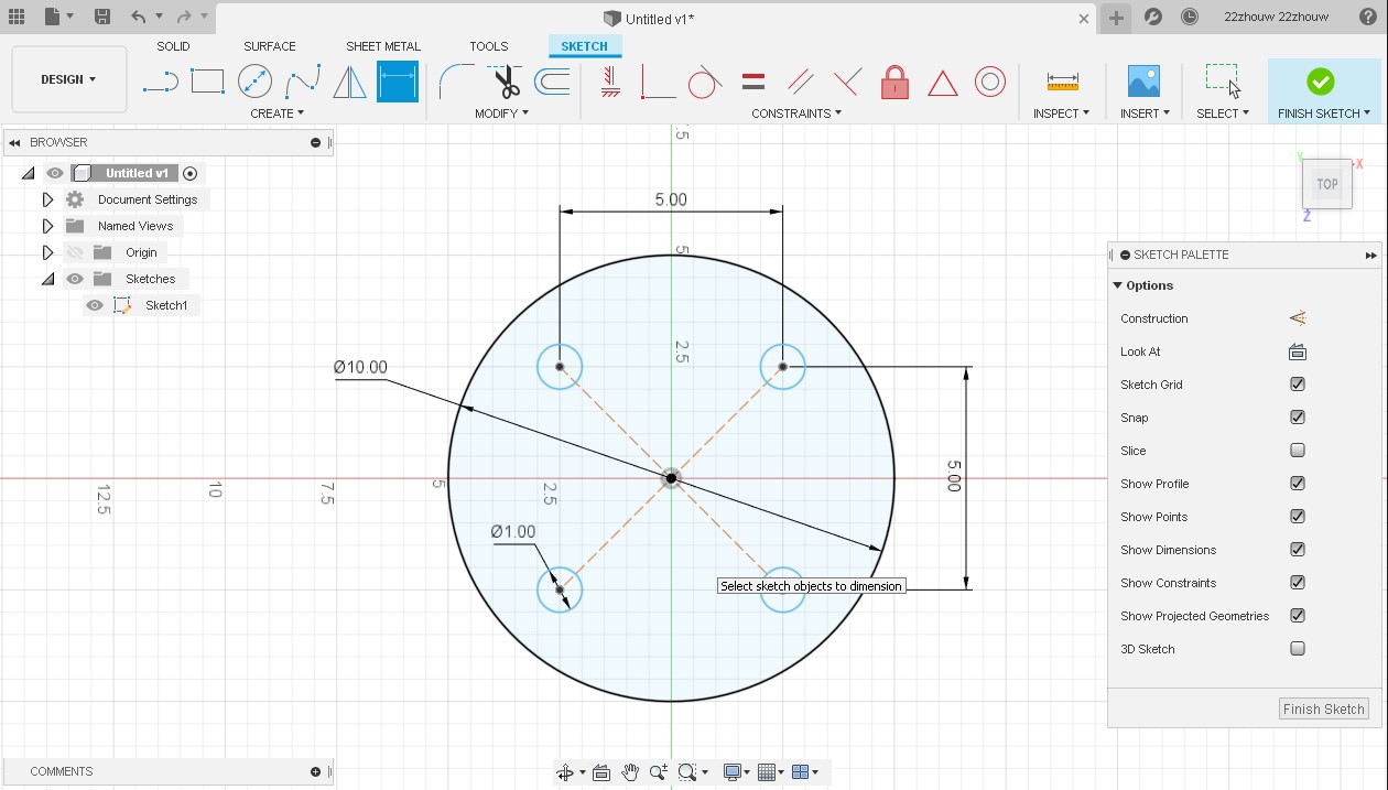
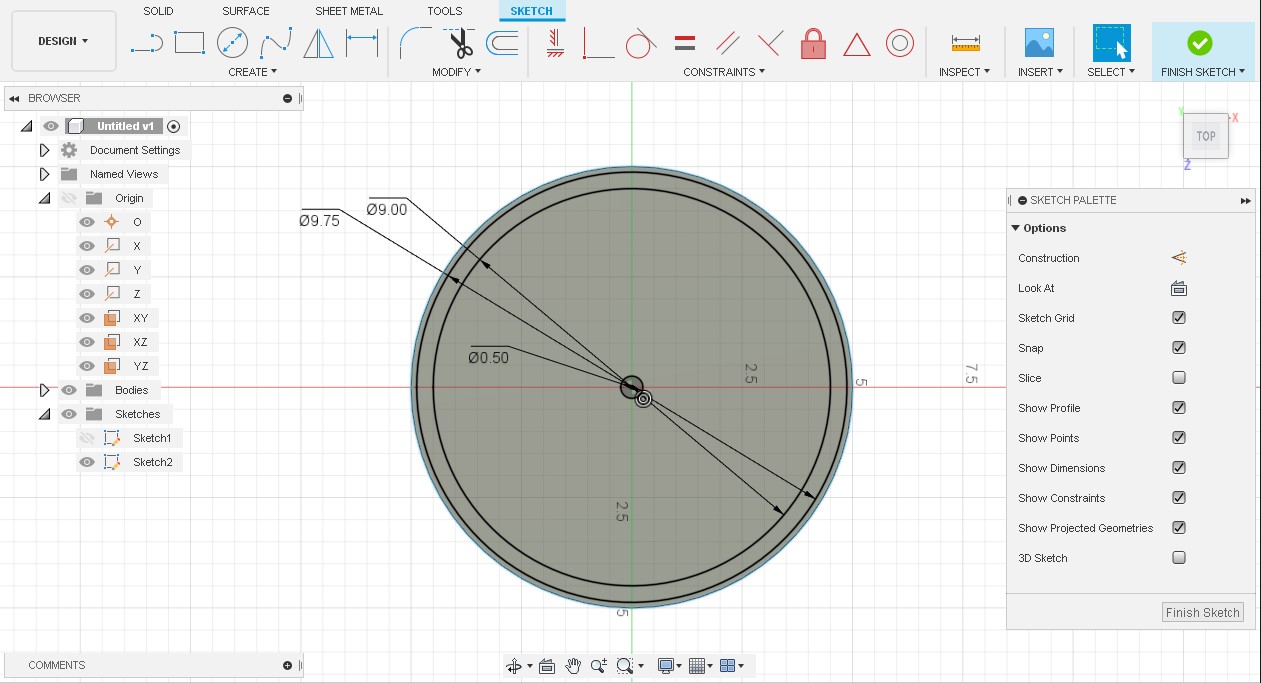
I started off by creating a circular base for my final project to accomodate how my fan blades would spin. In order to do so, I first created a sketch with a center diameter circle along with four inner circles for the rubber feet of my project.
Once we have the sketch down, we can select the entire sketch and press E on the keyboard to pull up the extrude command. After finishing each sketch, we can complete it by clicking the Finish Sketch button on the top right corner.
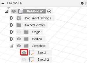
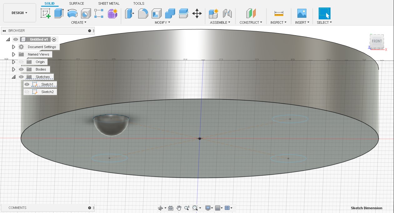
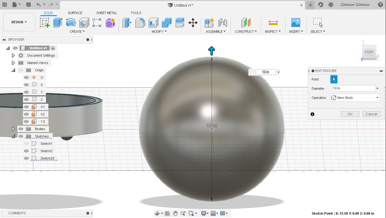
We can extrude our sketch by either dragging the arrow or typing the distance to extrude. Next, I can create the feet of my sketch by utilizing the sphere tool under the Create tab. The tool prompts to select the center point for the sphere so I utilize the sketch I made earlier. The eye icon in the browser tree allows us to show/hide bodies and sketches in order to remove any unnecessary clutter. In this case, I showed the sketch and placed my center point on my previously mapped circles. The rest is similar to creating a center diameter circle and I made the diameter of the sphere to be the same as in the first sketch.
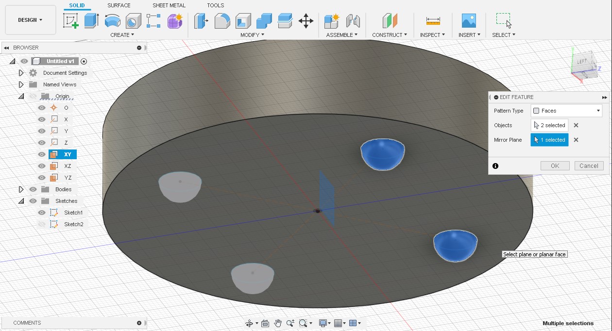
I am looking for four feet so I created one more sphere and used the mirror tool to mirror them both across the XY plane.
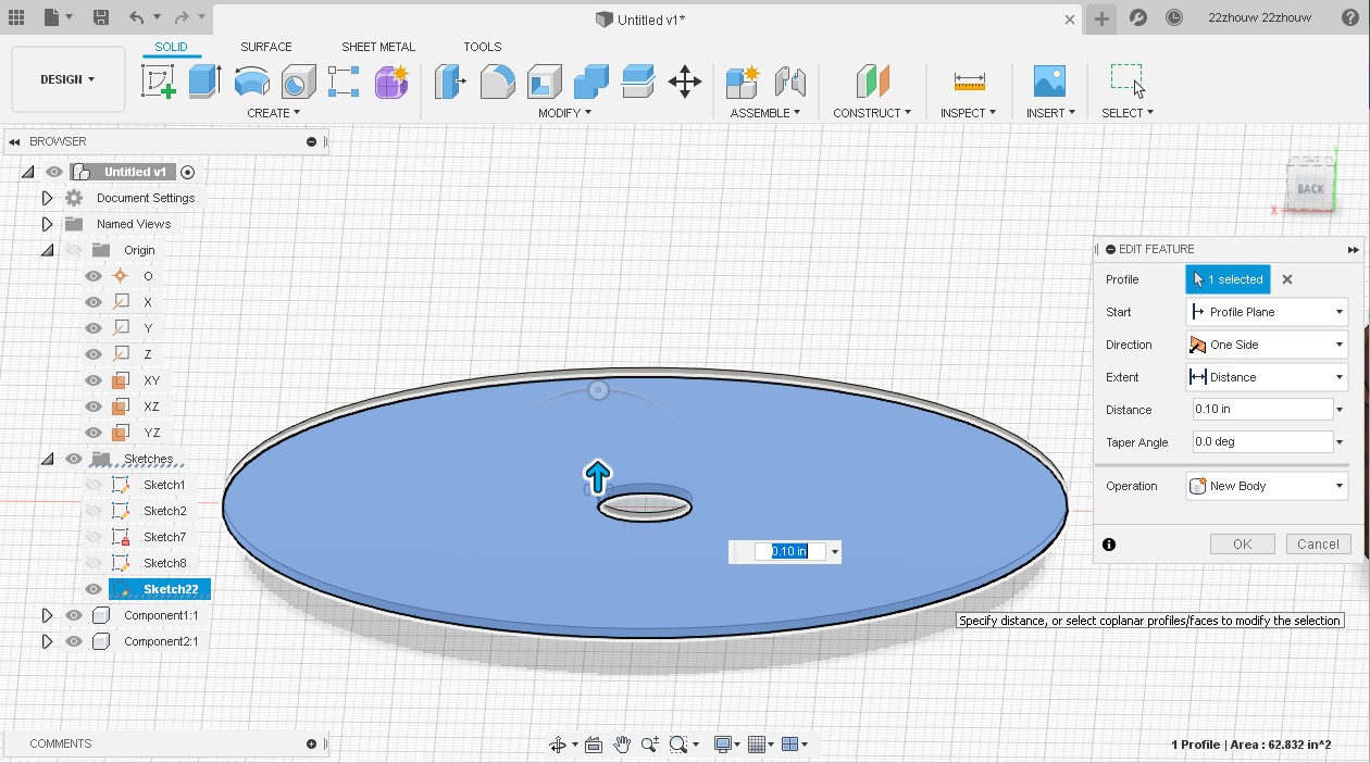
Now that my feet are done, I can hide the first sketch and move on to hollowing out my base. I created a sketch onto the top face of my base and made three center diameter circles. The smallest would be used later for the motor shaft, the middle for hollowing out the base, and the largest for a reference later on to create a fillet.
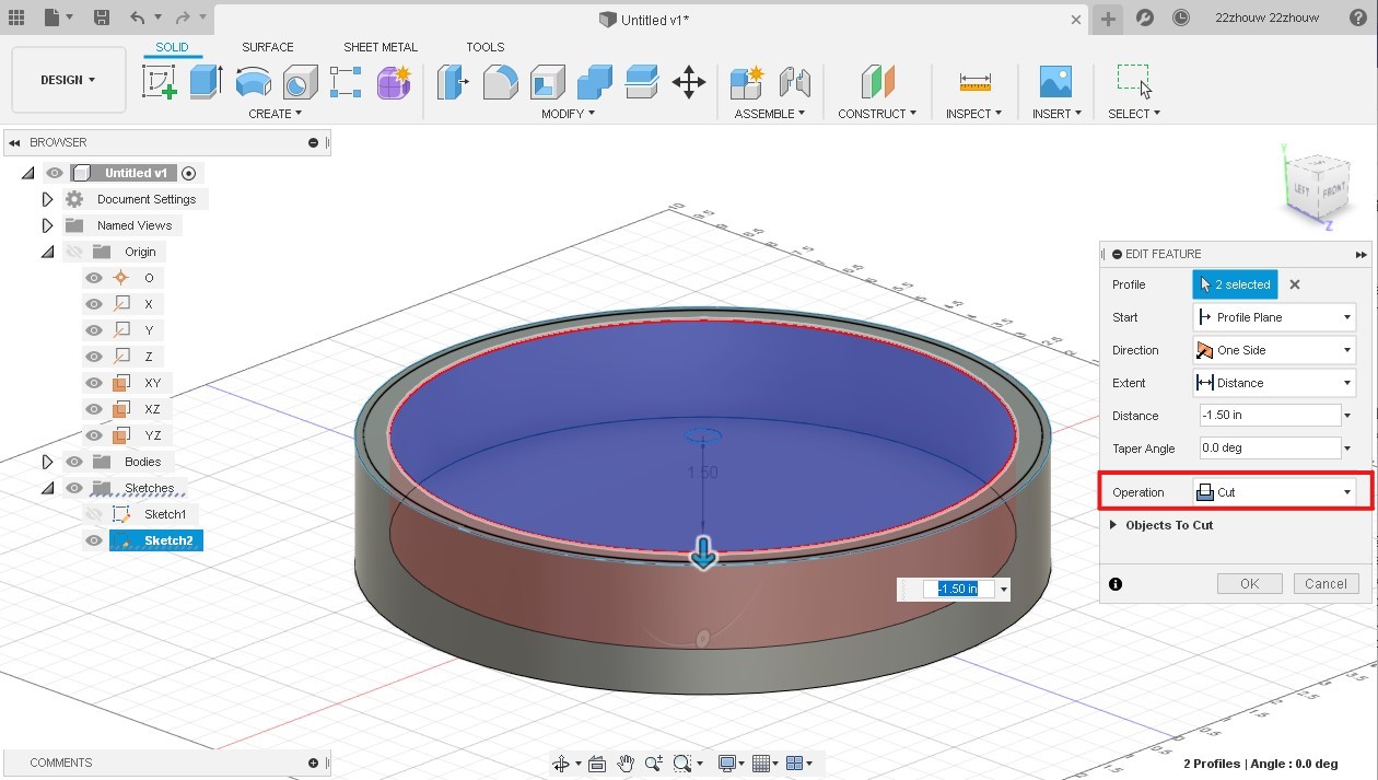
To hollow out the base, I used an extrude cut using the previous sketch. The extrude cut is similar to an extrude, however, you need to change the operation to a cut and drag the extrude into a body.
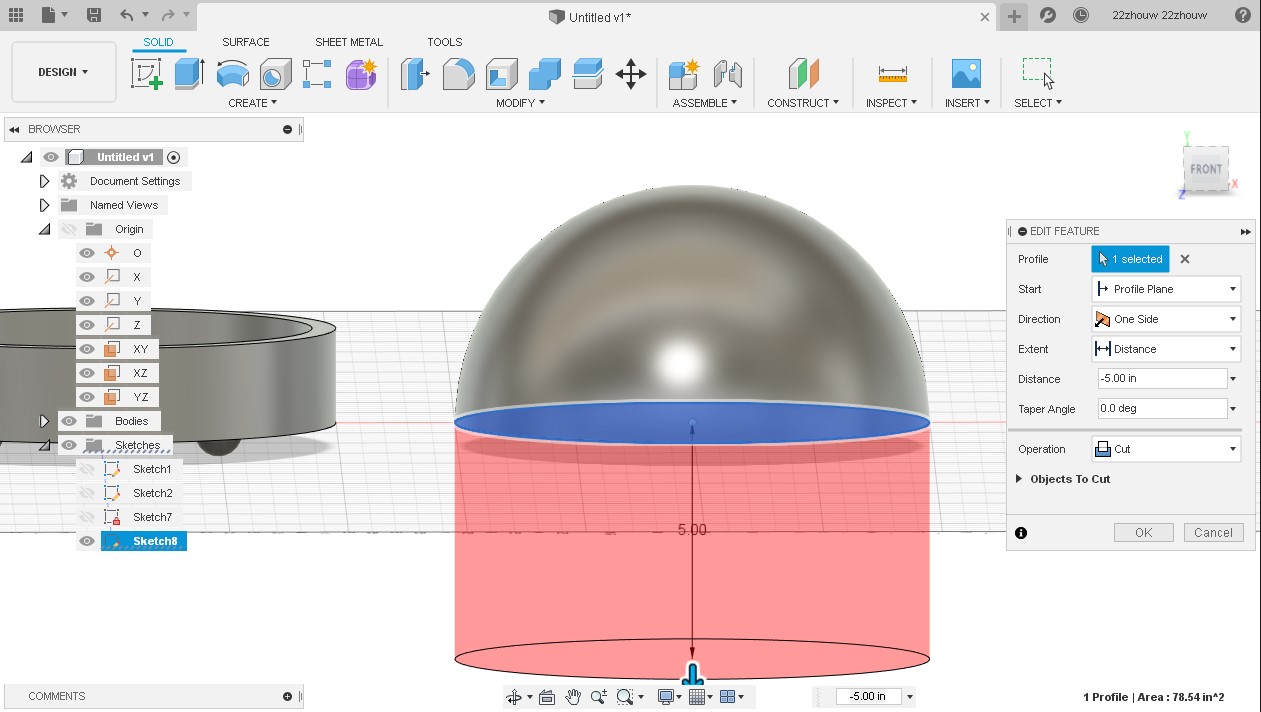
For the glass top I will put on top of my final project, I will use another sphere with the same dimensions as my base and do an extrude cut to create a semi-sphere.
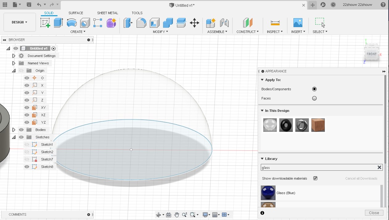
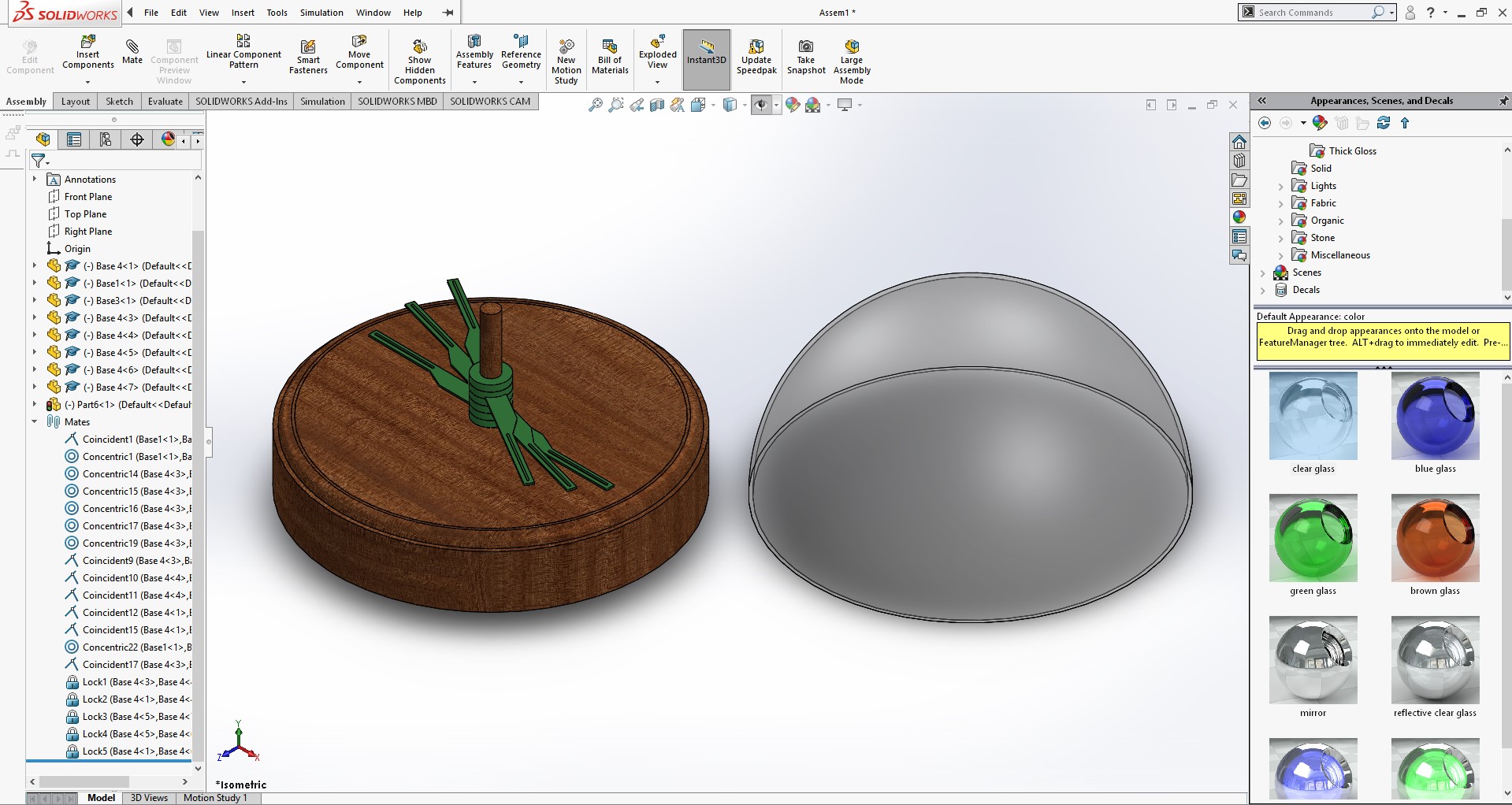
Changing the appearance is simple. Press A to pull up the Appearance tab on the right hand side on your screen and in the library, find what material you are looking for.
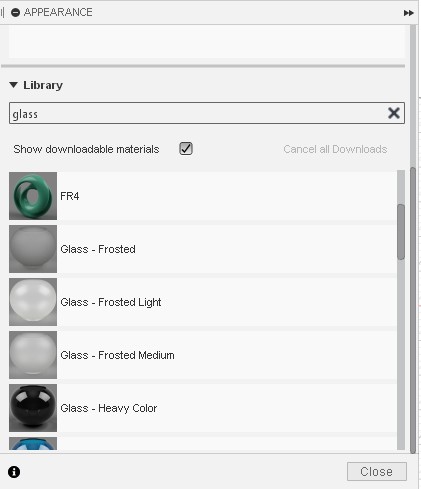
To apply the material to the object, simply drag the the material onto your body.
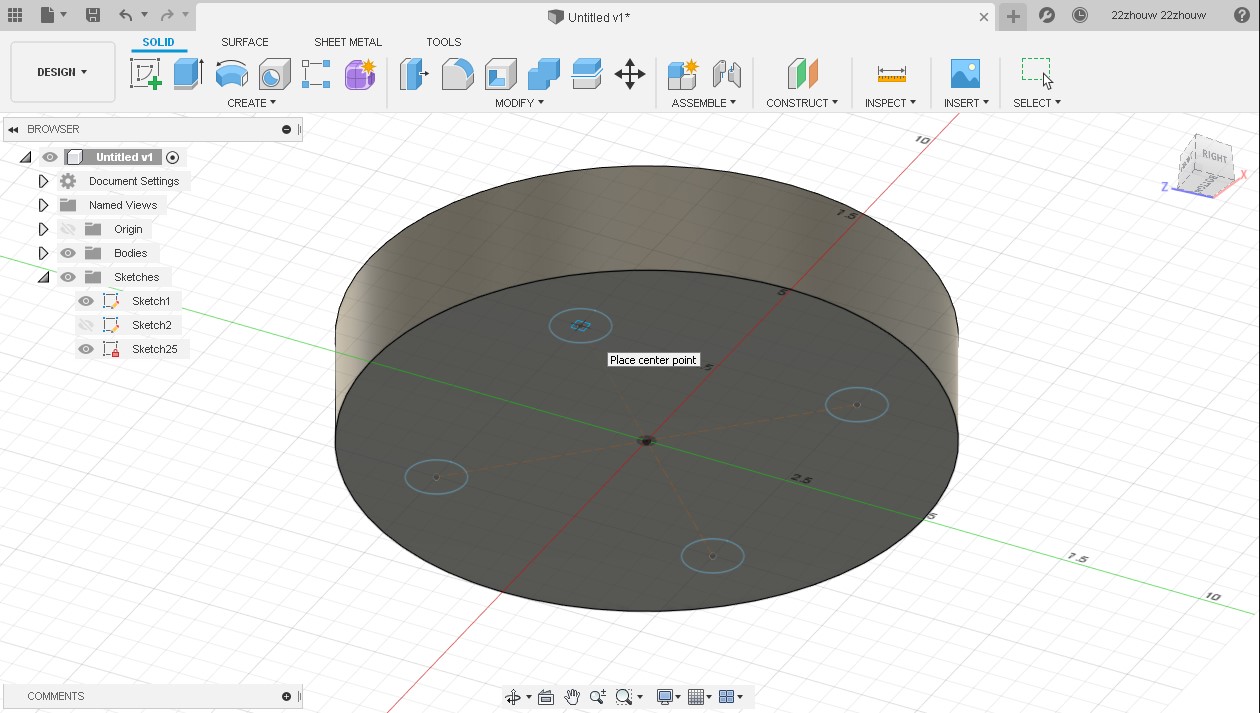
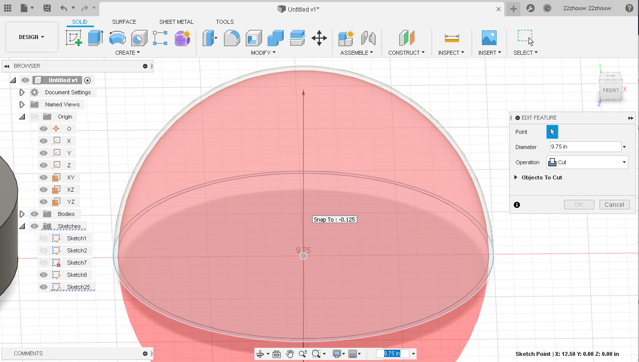
I hollowed out my sphere by creating a smaller diameter sphere inside of it and setting the operation to cut, similar to an extrude cut.
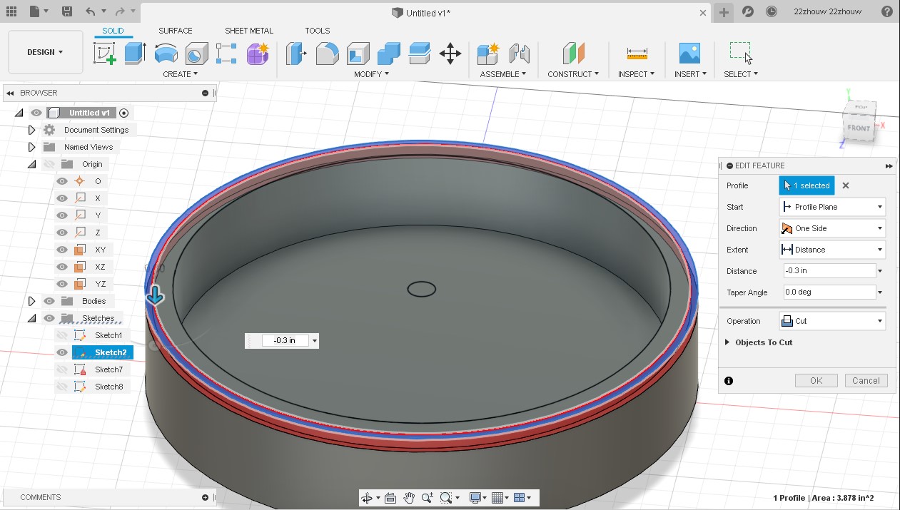
Next, I created a small extrude cut on the rim of the base for my new glass dome to fit into.
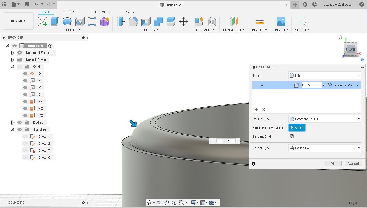
Due to the curvature of the glass dome, I needed a fillet on the edges next to the dome. I selected the edge I wanted to fillet and pressed the F key. The fillet rounds the edge using a value that specifies the radius of the fillet’s curvature.
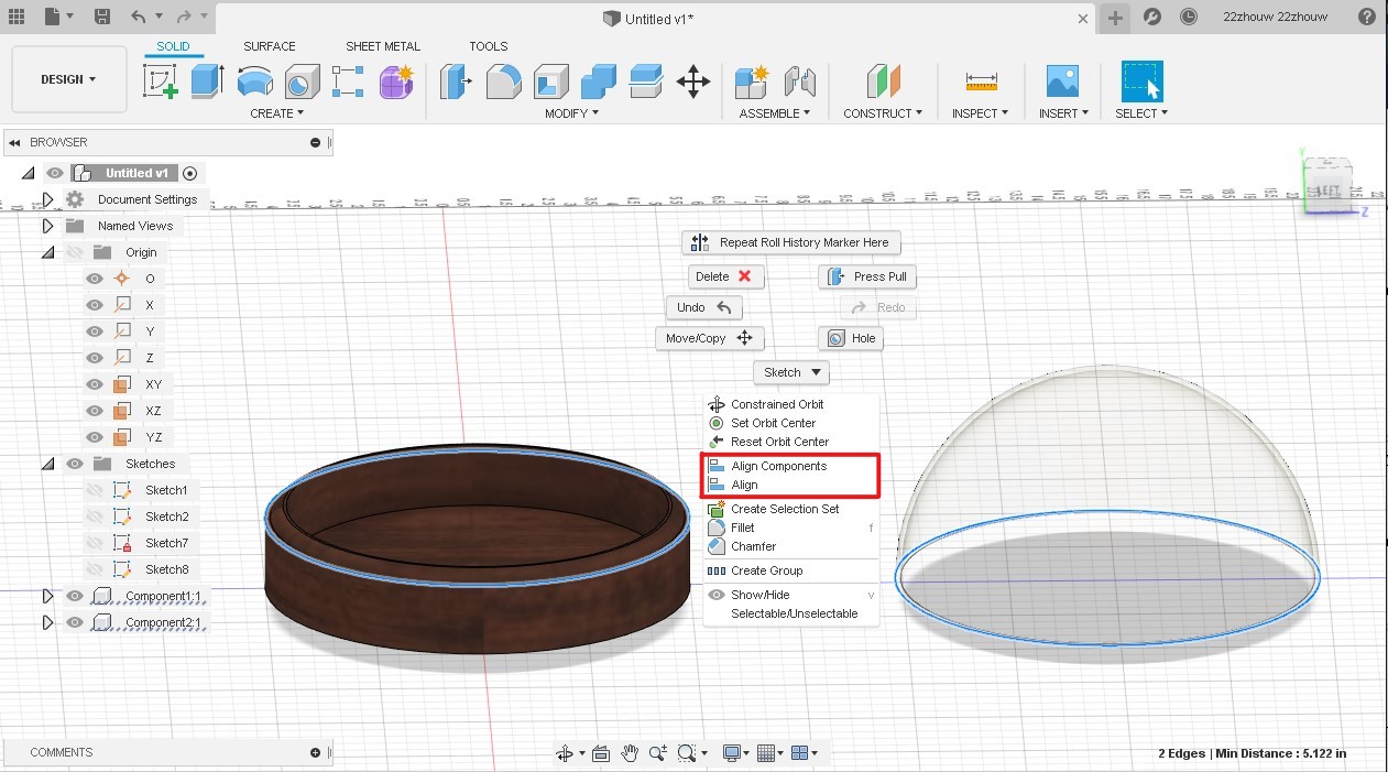
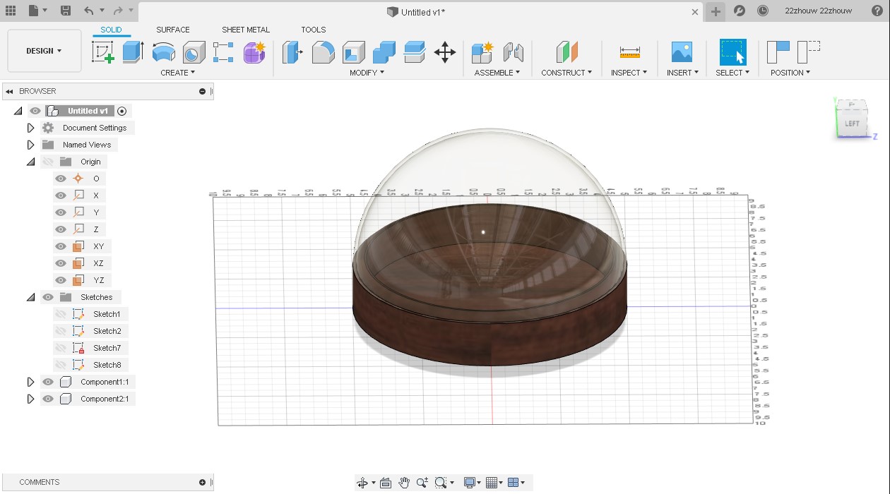
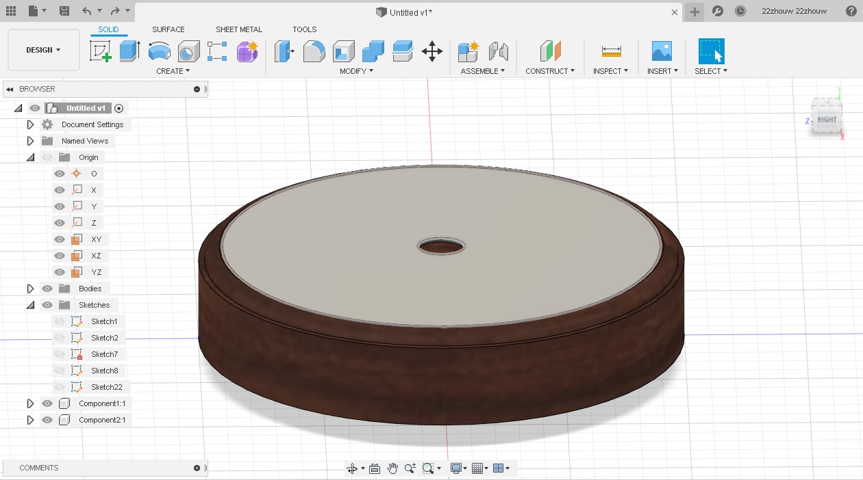
I also changed the material of my base to be a nice mahogany. Now, I want to test the fit of the glass dome on top of my base. I do this by selecting the two edges of the bodies that I want to combine. For the glass dome and base, it was the outer rim. By holding down the Ctrl Key, you can select multiple things. After I selected what I the edges, I right clicked on the mouse to bring up a menu of options. In this menu, we are looking for the Align button to align the two bodies.
I then sketched and extruded a lid for my base to hide the electronics from the outside. A hole is cut in the center to allow the motor shaft to pass through.
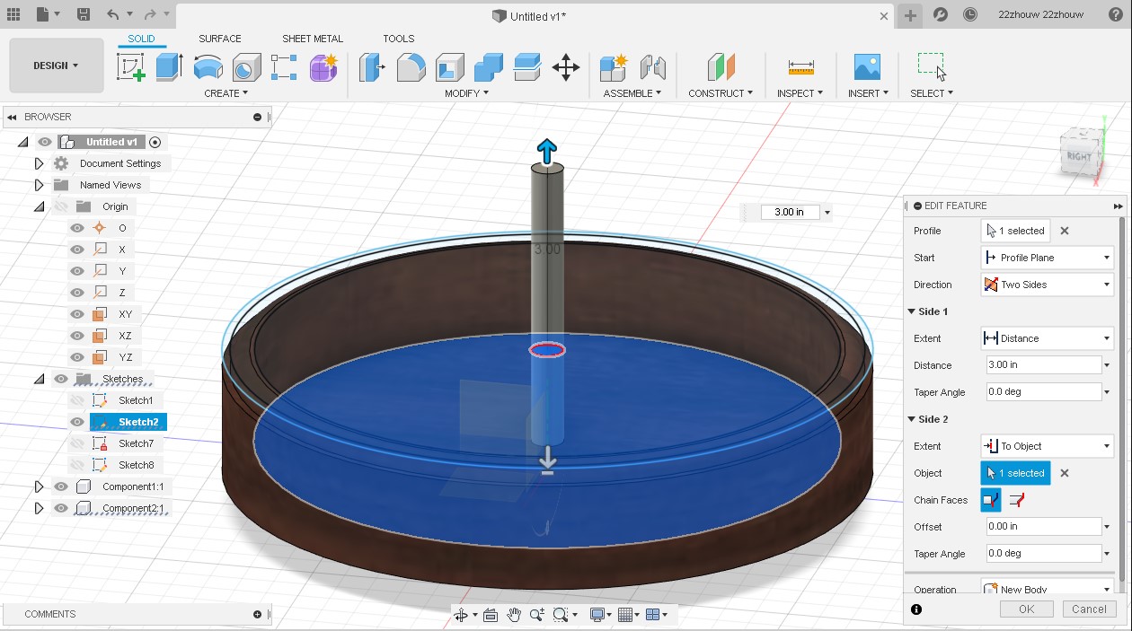
I created a motor shaft with a center diameter circle from a previous sketch and extruded it from two directions where one is extruded until it reached the bottom of the base. My fan blades will be anchored to this motor shaft to receive microcontroller input and spin.
I put everything together and this was my fusion prototype for my final project:
SolidWorks
I am more comfortable using SolidWorks to do CAD work so I used it to finish the rest of my model.
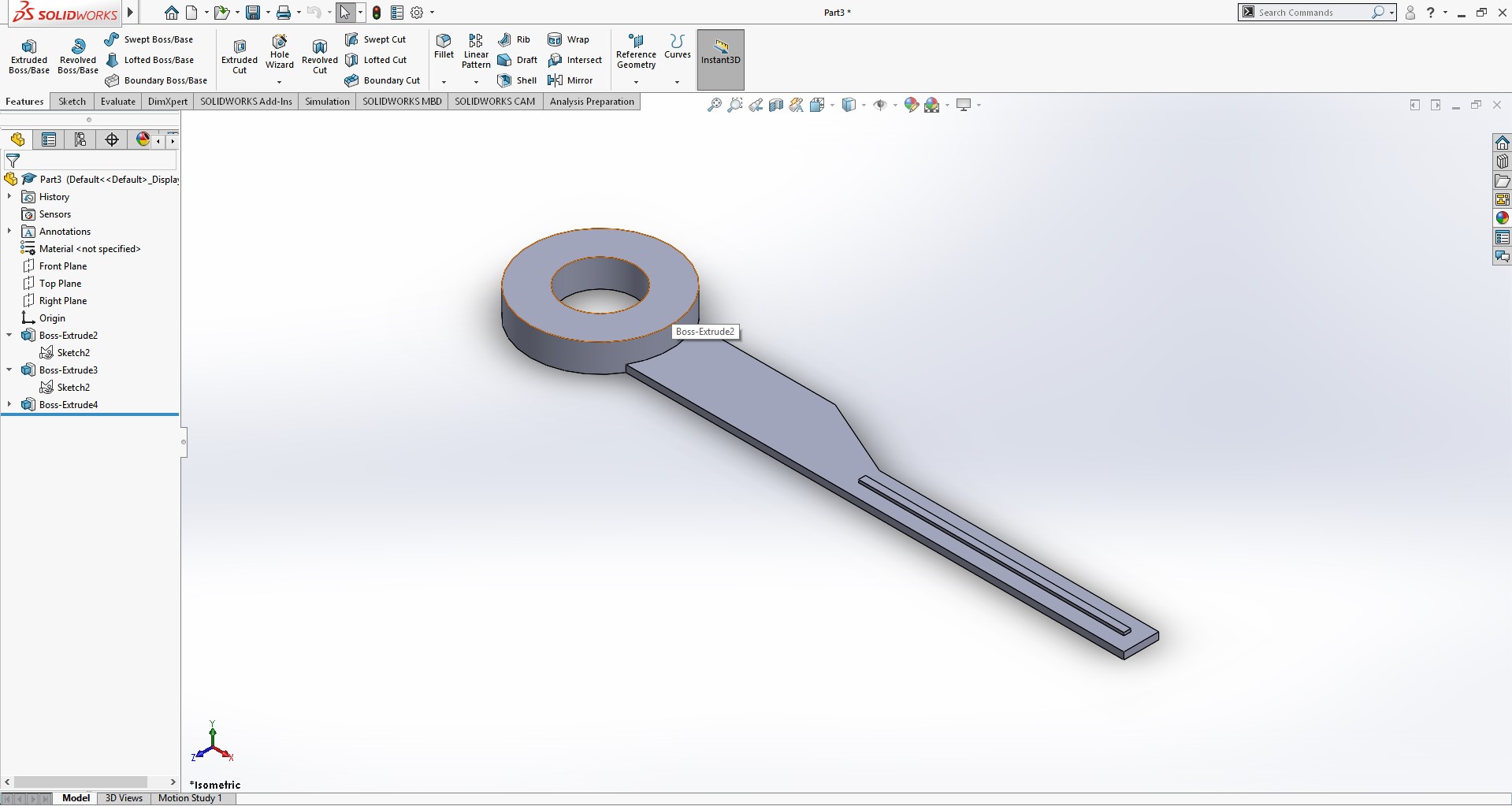
I recreated the entire model in SolidWorks since many file types that Fusion uses to export with does not translate over well into SolidWorks. Now once I fully recreated my model, I sketched a new fan blade that would spin around my motor shaft.
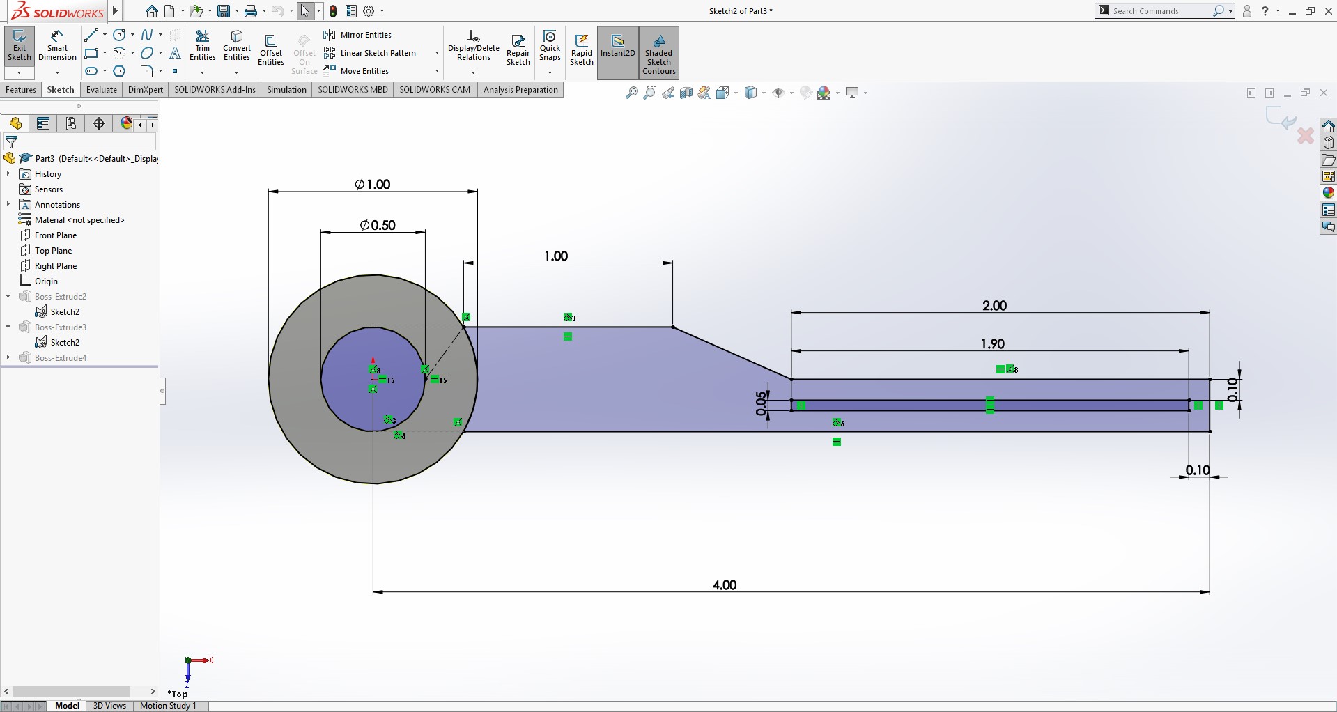
This was extruded out with a small rectangular prism exposed to resemble a LED strip for reference.
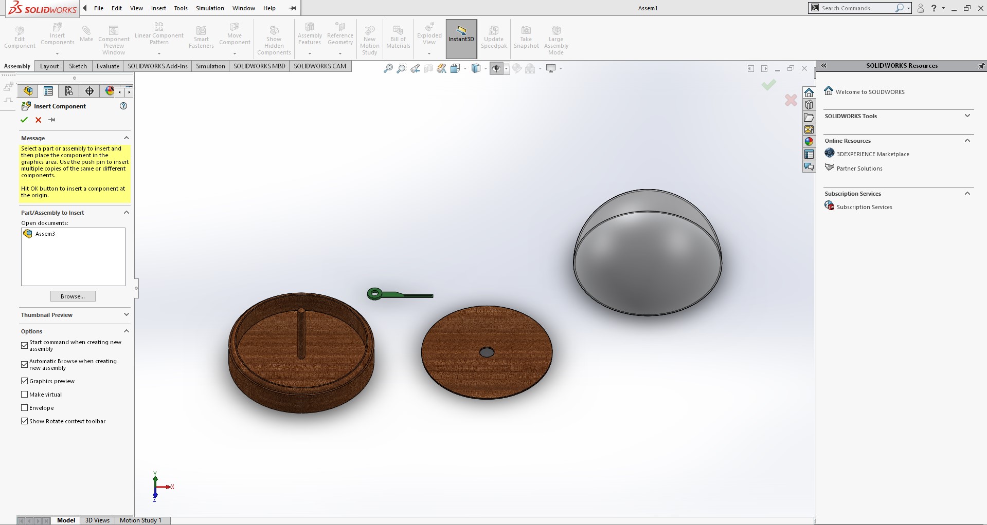
Contrary to how I made everything in one design in Fusion 360, SolidWorks requires you to create every part separate in its own file. Once everything is created, you can insert all the parts into one unified assembly.
With the fan blades, I utilized a concentric mate to center them all on the motor shaft. This centered each blade onto the motor shaft but allowed for free movement up and down the shaft.
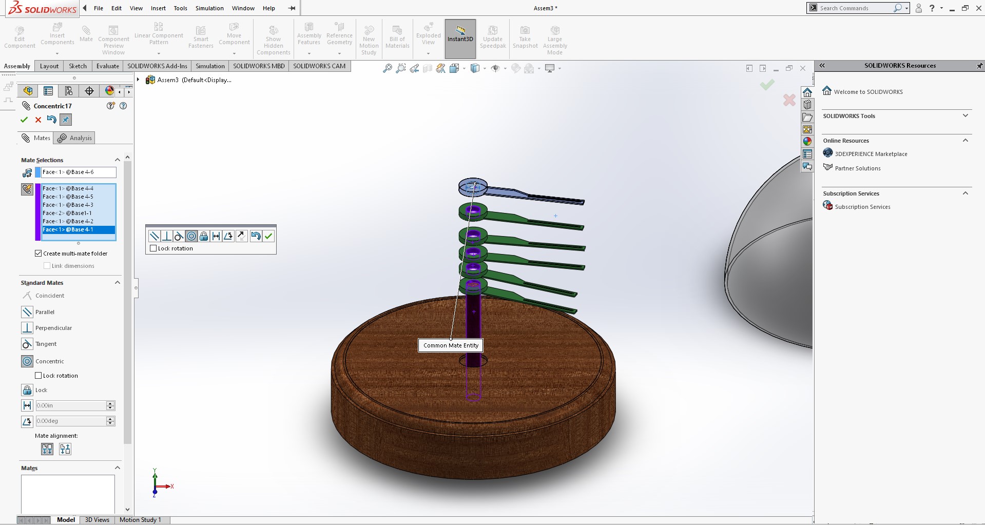
Now that they were centered, I then used a coincidence mate between each fin to make them stuck together and not freely moving on the shaft.
I also locked the rotation of the blades to each other so that when I spin one blade, the others spin also.
Now my CAD design is fully complete and is a good representation of what I seek to produce as my final project. I imported my SolidWorks assembly into Fusion 360 as Autodesk provides a useful hub to upload CAD files into. This is very useful due its capability of allowing users to embed 3D models into their webpages.
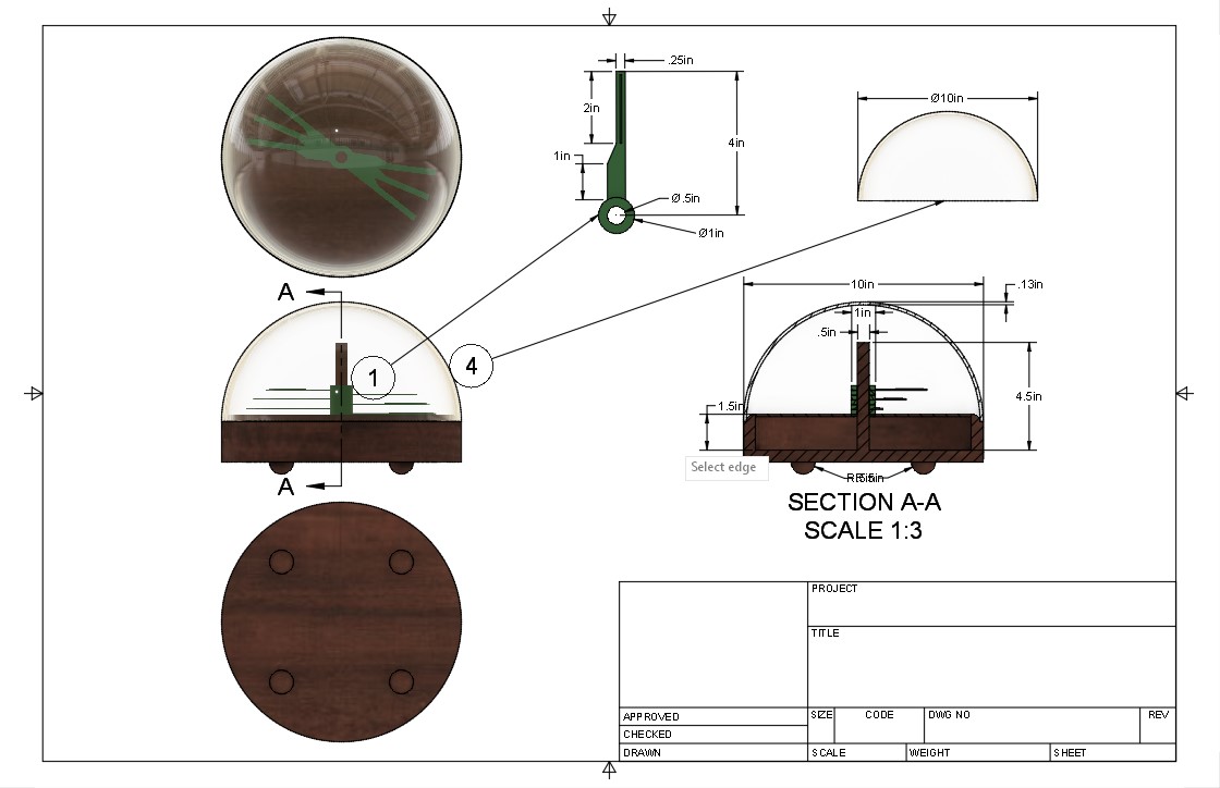
I used a drawing in Fusion 360 to display various views of my final project and useful dimensions for later reference.
Coming back, I think I could have locked the position of the blades relative to each other in addition to the motor mount and make the motor mount spin instead. My motor mount currently is not a separate part of my assembly so I can not move it independent of my base.
Inkscape
In week 4 I utilize Inkscape to separate a vector image into separate pieces in preparation for a sticker. Inkscape is a vector graphics editor that offers a variety of features for modifying images and uses vector graphics to enable an “unlimited” resolution unlike that of raster graphics.
For the sticker, I modified this vector image off the web:

I highlighted the background and separated crucial portions of the image to achieve the final product:

More detailed steps can be followed on the week 4 page.
Here are the files for this week: download