07. Computer Controlled Machining
Notes
Here are the notes.
Group Assignment
The group assignment is documented by Denise.
I will copy paste the steps written by Denis because they are consice & very well written.
- Measure the material. Each board could be slightly different.
- Prepare the file, we used RhinoCAM. This is the most time-consuming part.
- Prepare the file for the screws. Some boards could be bended so adding additional screws prevents parts from coming off.
- Upload files to the cloud.
- Fix the material to the table.
- Download the files in the machine computer and set the origin (X,Y,Z).
- Set the proper end-mill.
- Turn on the vacuum.
- Set the screws.
- Start with the screws-file.
- Then, set the screws on the spots.
- Run the file with the design.
- Vacuum the wood chips.
- Take out the cuts, remove the end-mil and put it away.
Feed Rate
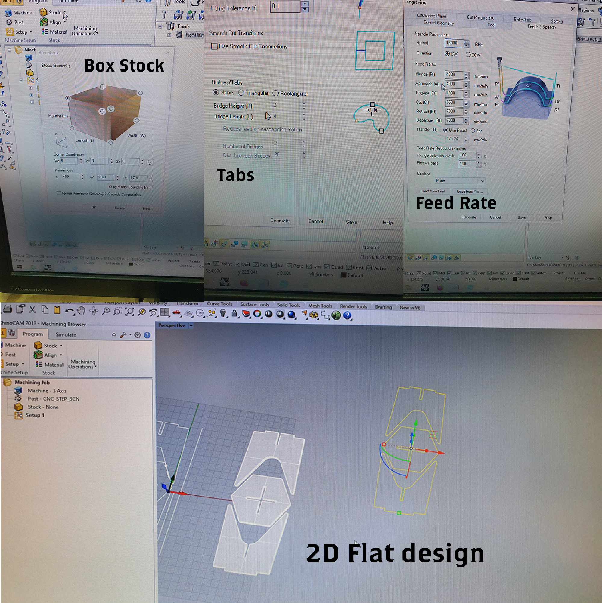
Settings for the cut We used a ∅6 mm Down cut Flat end mill. The formula used to calculate the tool’s feed and speed was: Feed rate = N x CPT x RPM
N = number of flutes CPT = chip load RPM = spindle rotational speed
Design
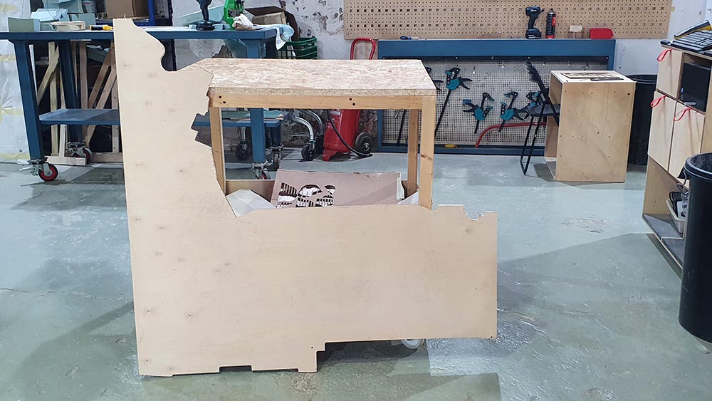
I decided to make a stool design.
I base it on a tutorial for AutoFusion
360 that right now I cannot find the link for.
In Rhino, we use the flat design. We need to do the T-Bones of the 6 mm end-mill in order for the assembling to be smoother. Also, we needed to change the thickness of the joints since the thickness of the material is 17.5 mm.
Preparing the file
We decide to leave the stool without the join showing from the top, so we pocket where the joint fits instead of profiling.
That meant reducing from the base by 10 mm in order for it to fit. This difference in the stool seat cut is modified while preparing in the RhinoCAM.
These are the main parameters to take into consideration:
Chipload
Manufacturer of the end mill usually give you the chart speed which will provide the chipload based on material. then you do the calculus.
Our 6mm is from CMT orange tools and its reference is 198.660.11
Board Size & Origin
1.Make a frame to define the size of the piece, then pick your material to be used later.
Box Stock —> machining operations 2D axis Select the origin Size of the wood but also decide the origin.
Holes for fixing on CNC base
select the holes on 2D design machining operations –> tool –> create the tool –> flat end mill settings –> select the speed –> clearence part macz+ 6 –> cut parameters tolerance 0.01 –> total cut depth
Profiling
–> Same tool –> same speed –> same tolerance —> cut outside because the shape i need is inside. —> Cut less depth because it is profiling.
Pocketing
Tool and Speeds already created for the holes. Same Tolerance. Conventional milling upcut
DONT FORGET THE TABS SO THE PIECES DONT MOVE.
File saving: .nc file
Save two files, one for the holes as they go first. The other is for the profiling and pocketing at once.
Machine Set-up
1.We picked a Birch plywood BB/CP piece of left-overs.
BB is quality of outer layer - inner layer, and CP is related to glue quality.
The thickness of this piece is of 17,5 mm, so had to modify the design as mentioned earlier.
2.Install the right mill. The one we have in the machine is a 6mm upcut, better for fast results and plastic.
in my case, I need a down cut because the wood is thick and it would give a better quality.
3.Place the piece of wood.
4.Clean chips leftover.
5.Wear protective mask & ear stuff.
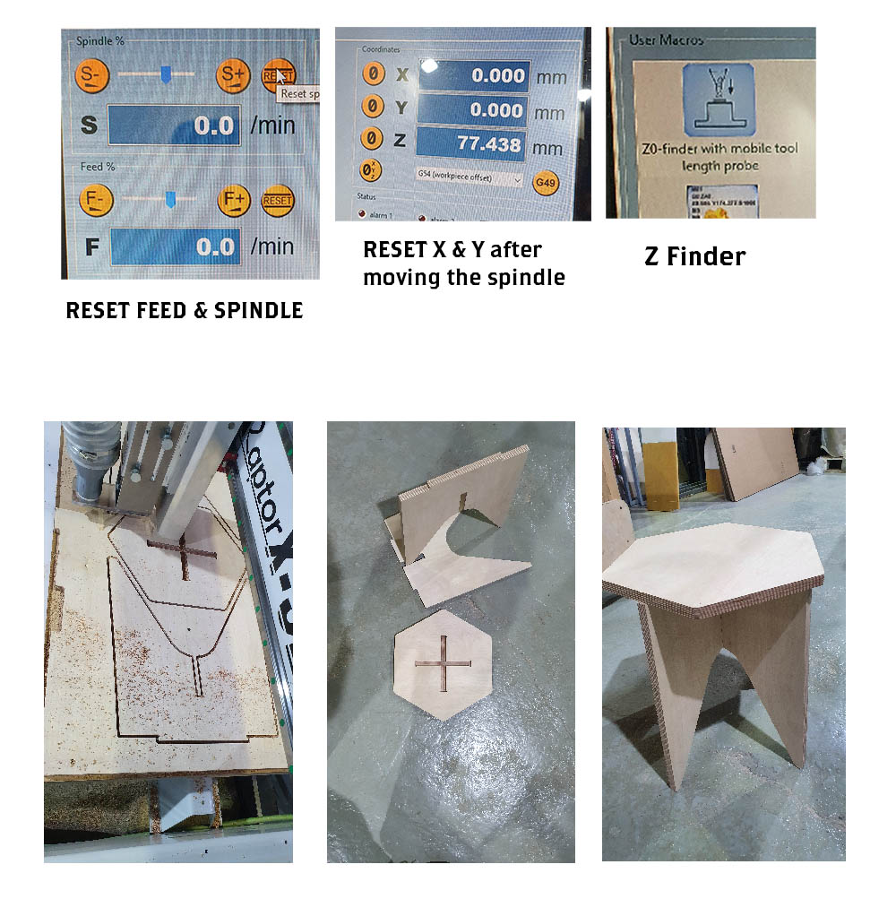
5.Set X
Set Y
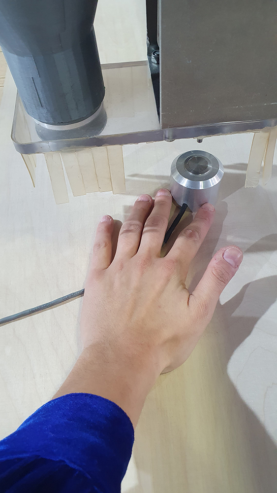
Set Z with the physical button.
Reset Feed & Spinner in case someone else fed them.
6.Start the holes file.
7.Insert screws while holding down wood.
8.Throw cutting file.