15. Wildcard week
In this week we used the Robotic Arm to paint with light.
To start off, we had a local class where Josep Marti explained how the robotic arm works and how to set up the file for it.
Links to presentations:
- Documentation on the Robots plugin in Grasshopper
- Link for the Robots Plugin Grasshopper
- Documentation to Download
Grasshopper Script Explained:
First section is setting the type of machine we are using We are using a IRB140

Initial and final position:
- 6 angles to define (from the base to the tool)
- Make them into a list by merging them
- Make it into radians (which is what the machine understands)
- Create target (which is the different positions or planes that we want it to move to)

Every time you want to move you have to create a target for it to move to.
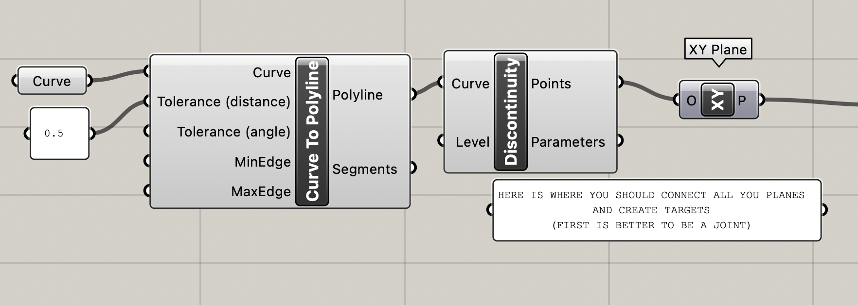
The Curve
- Make a curve wherever you want on Rhino and attach it to the Curve on Grasshopper
- Divide it into segments by connecting it through the 'curve to polyline' and 'discontinuity'
- Create a plane where all the points are
- Make sure to always align the planes so the robot can easily move from one to the next
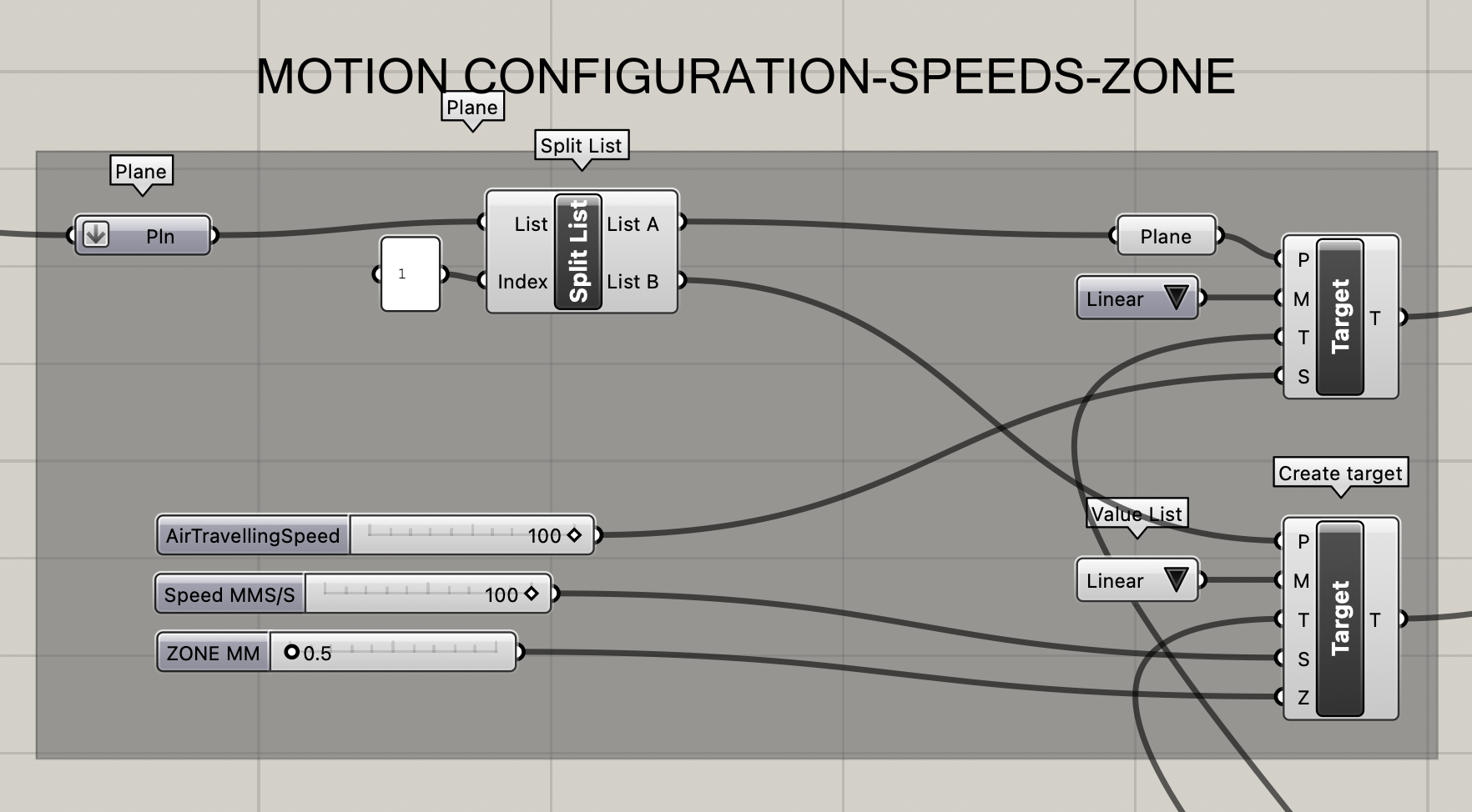
Creating Targets for the Different Planes (telling it which type of movement to take)
- Divide the list of planes into the first one and then all the rest in another (essentially making it into two lists, list A is first plane and list B is all other planes)
- Connect each list to a target
- Define what type of movement (liner or joint etc)
- Defining the speed of traveling
- Defining the type of tool we will be using
- Zone is the approximation zone to the point
Configuring the End Effector (the tool we will be using)
- You need the full 3d model of the tool (in our case we just put it at 0,0,0 of the robot)
- You need the point that we will calibrate (the Tool Center Point) (In our case we did not need to callibrate the TCP because we used the 0,0,0 of the robot itself)
- Define a plane for it
- Then define the orientation of the plane
- Then create the tool to plug into the robot
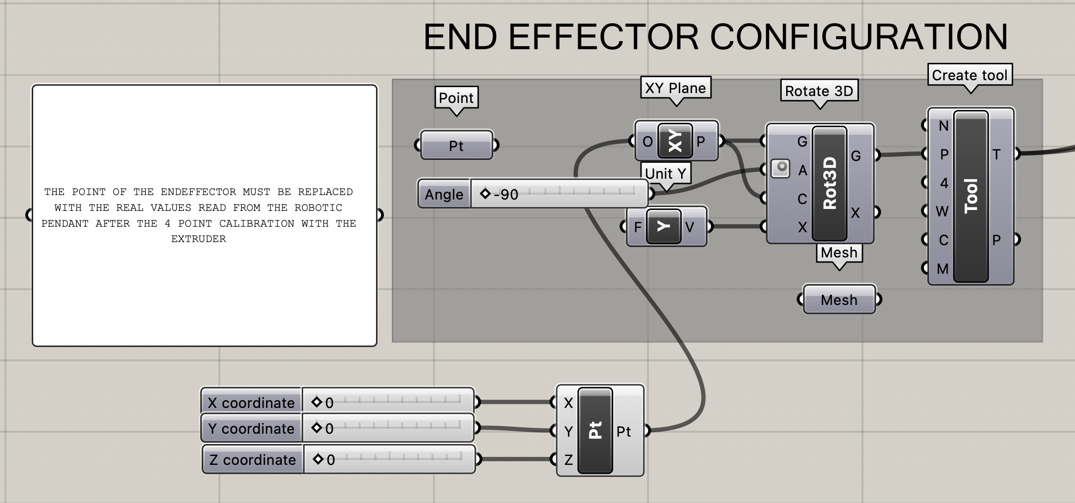
IMPORTANT
- You have to go to the machine and measure the actual coordinates before coming back and putting them instead of the original point
Merging all the targets / Flattening all the lists of lists to one single list
- You put them in order in this merge option
In our case, we removed the first and last list so that it doesn't park. It will go to the first position immediately and then when it reaches the last position it stays in place.

Assembler
- First option is the name for the file
- Import the robot next
- Importing all the targets
- It will either give you the code or the error

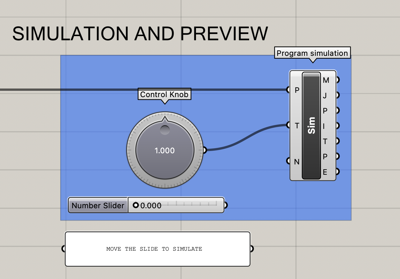
In the end, the slider can show you an animation of how the robot would move.
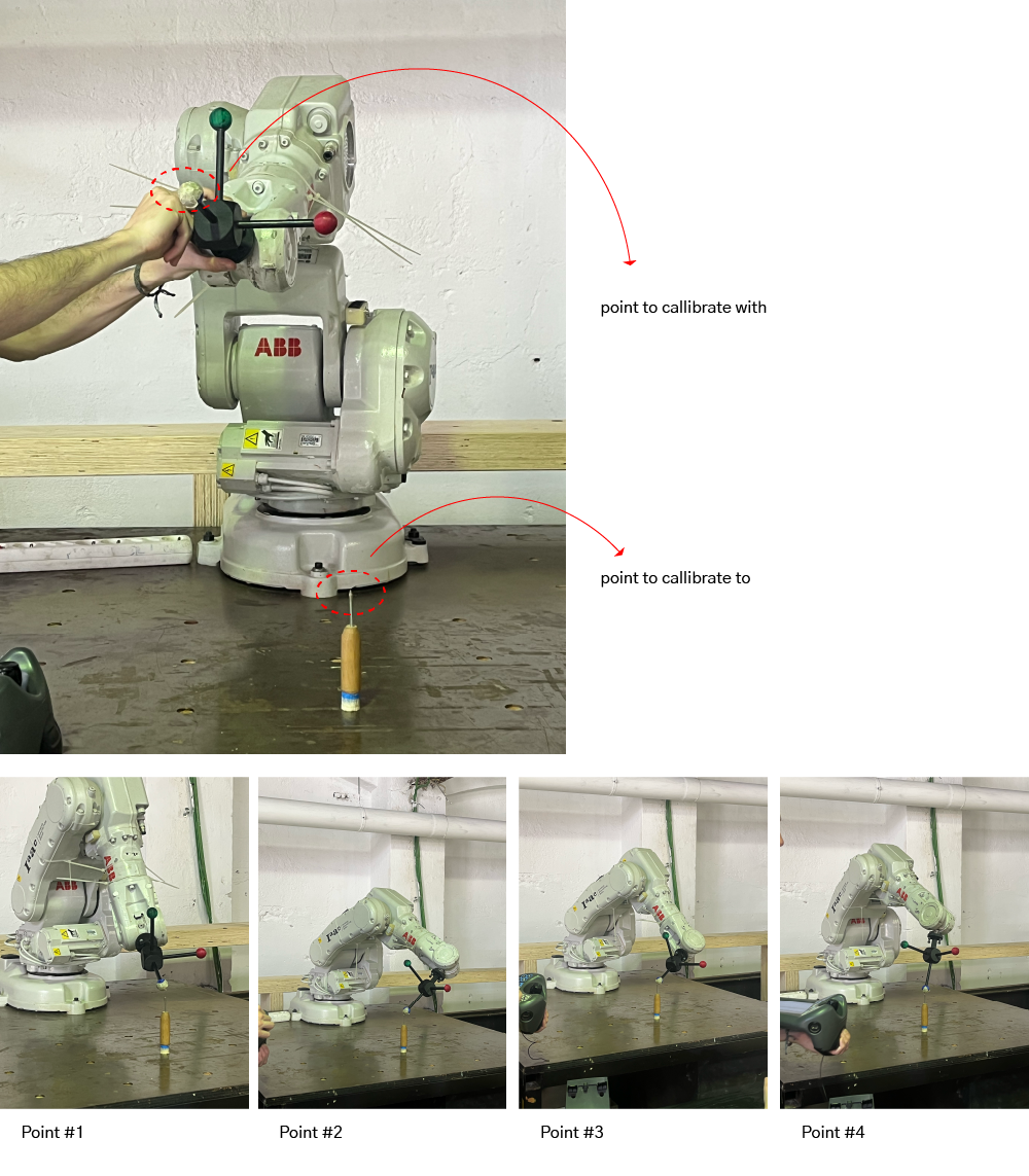
Tool Center Point
The Tool Center Point (TCP) is the point used to move the robot to a Cartesian position. It is the point of rotation. It is callibrated by using one point on the bed and placing the arm in a minimum of 4 locations around it touching it in the center.
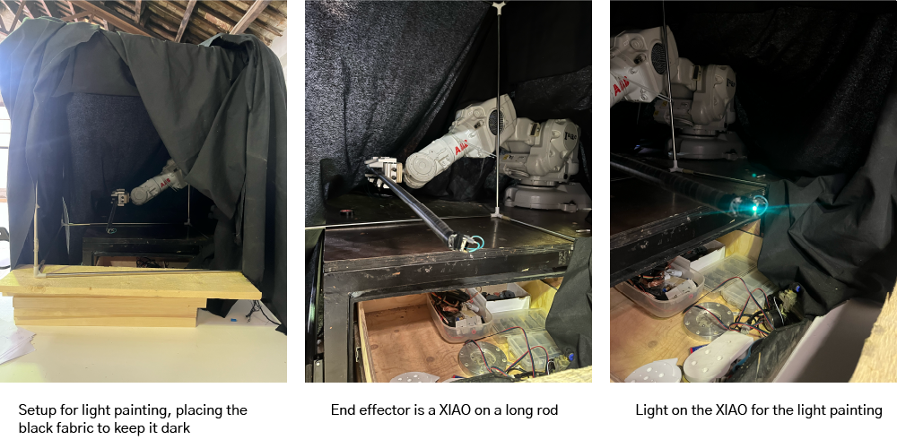
XIAO
Since the robot has multiple Digital pins available, we attached the Xiao to pin 11 and had it turn on and off the LED manually with one of the buttons on the controller. It was an RGB LED in a rainbow effect.
Design
I designed a simple eye and then arraycrv it to a rectangle size of 350 x 350 mm to match the space we had available.
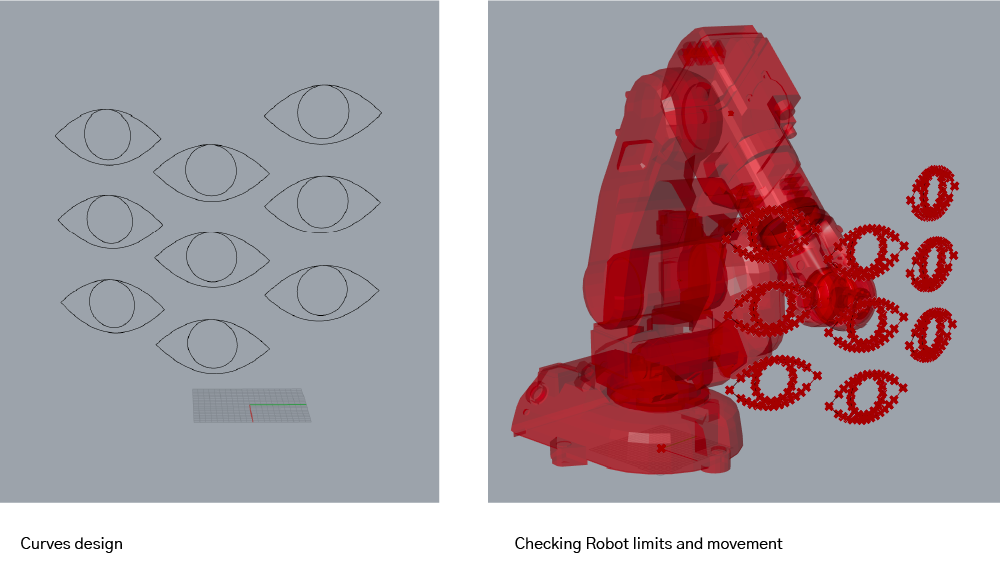
Simulation
Final
Taking a long exposure photo and a screen recording of it I was able to get these results!


Files
-
Files: File for Light Drawing ↩