6. Embedded Programming
GROUP ASSIGNMENT
Using the ESP32 board I designed and milled, I controlled the RGB LED on it using a potentiometer.
A potentiometer is a manually adjustable variable resistor with 3 terminals. Two of the terminals are connected to the opposite ends of a resistive element, and the third terminal connects to a sliding contact, called a wiper, moving over the resistive element. To adjust the output voltage the sliding contact gets moved along the resistor on the output side.
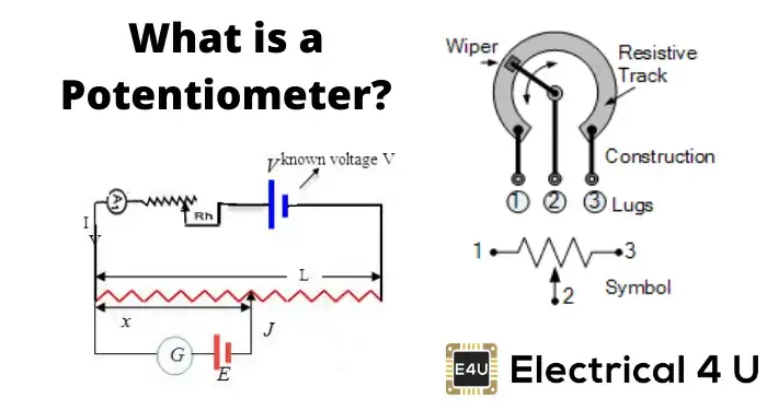

Potentiometer Working
Code
const int potPin = 34;  // Analog pin connected to the potentiometer

void setup() {
  Serial.begin(9600);  // Initialize serial communication
}

void loop() {
  int sensorValue = analogRead(potPin);  // Read the potentiometer value
  float voltage = sensorValue * (3.3 / 4095.0);  // Convert ADC value to voltage (assuming 3.3V reference voltage)

  Serial.print("Potentiometer Value: ");
  Serial.print(sensorValue);
  Serial.print(" | Voltage: ");
  Serial.println(voltage, 3);  // Print voltage value with 3 decimal places

  delay(1000);  // Wait for 1 second before reading again
}
In the code above, the potentiometer placed on the esp32 GPIO34 reads the values and converts them to voltages. Maxiumum voltage is 3.3. There is also a delay of 1 second between readings. In the loop, there are serial prints to show the sensor value and the voltage up to 3 decimal points.
Showing the values in both the ADC Value and the Voltage conversion while rotating the potentiometer.
Potentiometer + LED
Code
const int potPin = 4;   // Analog pin connected to the potentiometer
const int ledPin = 13;    // PWM pin connected to the LED

void setup() {
  pinMode(ledPin, OUTPUT);   // Set the LED pin as an output
  Serial.begin(9600);        // Initialize serial communication
}

void loop() {
  int sensorValue = analogRead(potPin);  // Read the potentiometer value
  int brightness = map(sensorValue, 0, 4095, 0, 255);  // Map potentiometer value to LED brightness (0-255)

  analogWrite(ledPin, brightness);  // Set the LED brightness

  Serial.print("Potentiometer Value: ");
  Serial.print(sensorValue);
  Serial.print(" | Brightness: ");
  Serial.println(brightness);

  delay(100);  // Delay for stability
}

# using the WS2813 RGB LED

#include <Adafruit_NeoPixel.h>

#define LED_PIN     38     // Pin connected to the data input of the WS2813 LED
#define POT_PIN     4    // Analog pin connected to the potentiometer

Adafruit_NeoPixel led(1, LED_PIN, NEO_GRB + NEO_KHZ800);

void setup() {
  led.begin();
  led.show();  // Initialize LED to 'off'
  Serial.begin(9600);  // Initialize serial communication
}

void loop() {
  int sensorValue = analogRead(POT_PIN);  // Read the potentiometer value
  int brightness = map(sensorValue, 0, 4095, 0, 255);  // Map potentiometer value to LED brightness (0-255)

  led.setBrightness(brightness);  // Set the brightness of the LED

  // Set the color of the LED to red
  led.setPixelColor(0, led.Color(255, 0, 0));
  led.show();  // Update the LED

  Serial.print("Potentiometer Value: ");
  Serial.print(sensorValue);
  Serial.print(" | Brightness: ");
  Serial.println(brightness);

  delay(100);  // Delay for stability
}
In this code, the same potentiometer values and conversions are used with the addition of an LED that changes its brightness depending on the potentiometer values. The potentiometer works as a slider. In this code, the sensor value is mapped to the brightness of the LED.
Showing the sensor vlaues along with the mapped brightness
Potentiometer + RGB LED WS2813
Code
#include <Adafruit_NeoPixel.h>

#define LED_PIN     38     // Pin connected to the data input of the WS2813 LED
#define POT_PIN     4    // Analog pin connected to the potentiometer

Adafruit_NeoPixel led(1, LED_PIN, NEO_GRB + NEO_KHZ800);

void setup() {
  led.begin();
  led.show();  // Initialize LED to 'off'
  Serial.begin(9600);  // Initialize serial communication
}

void loop() {
  int sensorValue = analogRead(POT_PIN);  // Read the potentiometer value

  // Calculate color components based on potentiometer value
  int red, green, blue;
  if (sensorValue < 2048) {
    // Sunset to sunrise transition
    red = map(sensorValue, 0, 2047, 255, 0);  // Red decreases
    green = map(sensorValue, 0, 2047, 150, 0);  // Green decreases
    blue = map(sensorValue, 0, 2047, 0, 255);  // Blue increases
  } else {
    // Sunrise to sunset transition
    red = map(sensorValue, 2048, 4095, 0, 255);  // Red increases
    green = map(sensorValue, 2048, 4095, 0, 150);  // Green increases
    blue = map(sensorValue, 2048, 4095, 255, 0);  // Blue decreases
  }

  // Set the color of the LED
  led.setPixelColor(0, led.Color(red, green, blue));
  led.show();  // Update the LED

  Serial.print("Potentiometer Value: ");
  Serial.print(sensorValue);
  Serial.print(" | Red: ");
  Serial.print(red);
  Serial.print(" | Green: ");
  Serial.print(green);
  Serial.print(" | Blue: ");
  Serial.println(blue);

  delay(100);  // Delay for stability
}
In this code, the WS2813 RGB LED is used to transition the color from one to the other as the potentiometer is turned. It reads the sensor value, is less than 2048 it maps the LED and transitions it from 'sunset' to 'sunrise'.
Showing the mapping of the sensor values to the R, G, and B values.