12. Output Devices
GROUP ASSIGNMENT
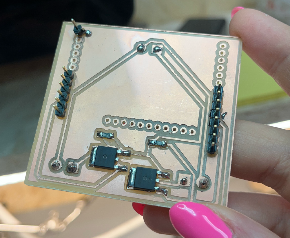
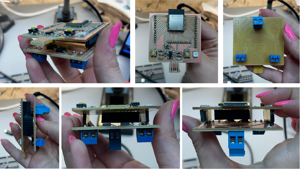
For the final project, I have built a shield for my ESP32 board.
Components:
- Pump 1
- Pump 2
- Power Supply
- MOSFET 1
- MOSFET 2
Transistor
A transistor is a miniature semiconductor that regulates or controls current or voltage flow in addition amplifying and generating these electrical signals and acting as a switch/gate for them. When working as an amplifier, a transistor transforms a small input current into a bigger output current. As a switch, it can be in one of two distinct states -- on or off -- to control the flow of electronic signals through an electrical circuit or electronic device.
There are two primary types of transistors. The first is the Bipolar Junction Transistor (BJT) and the second is the Field Effect Transistor (FET). MOSFETs are a type of FET. BJTs are usually used for electrical currents of under one amp, while MOSFETs are typically used for higher-current applications.
Mosfet
In this case, I used the MOSFETs to connect to the pumps and act as a switch. A MOSFET is a metal–oxide–semiconductor field-effect transistor. It is an electronic device used to switch or amplify voltages in circuits. It is a voltage controlled device and is constructed by three terminals. Their primary use is to control conductivity, or how much electricity can flow, between its source and drain terminals based on the amount of voltage applied to its gate terminal.
Schematic

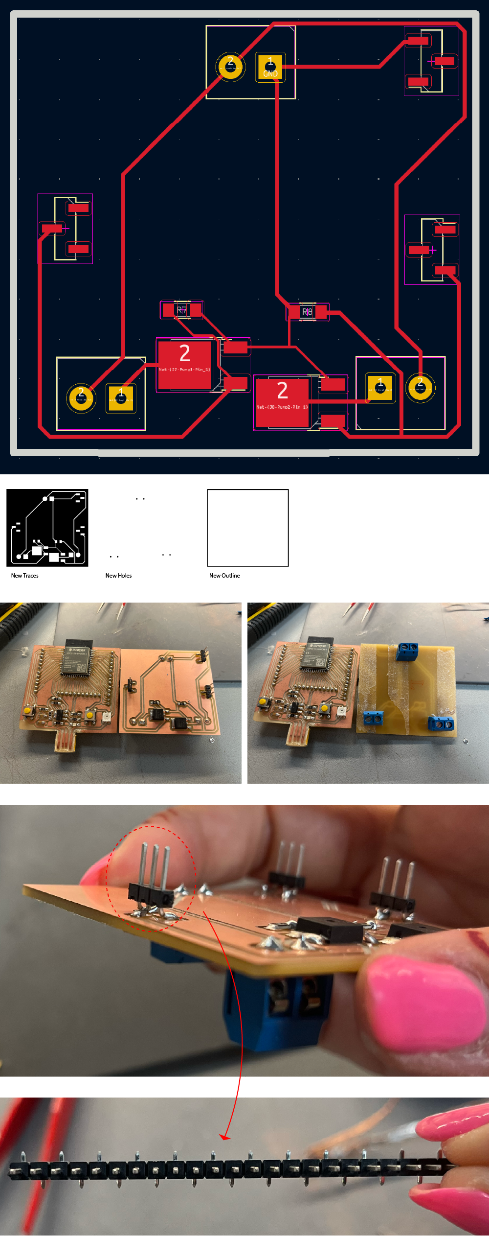
PCB Design
The output board is meant to control two pumps and be attached to the microcontroller directly. The pins are placed in their exact position along with the outline to make sure that everything is aligned. Other than that. the only other parts I need are the MOSFETs and resistors for each pump. The MOSFETs connect to the pumps through connectors that are attached to the back of the board. The external poewr supply is also attached through the connectors placed on the back of the board through the holes and soldered to the pads.
The RFD16N05LSM MOSFET was used for its characteristics as the pump and external power supply are both 12V.
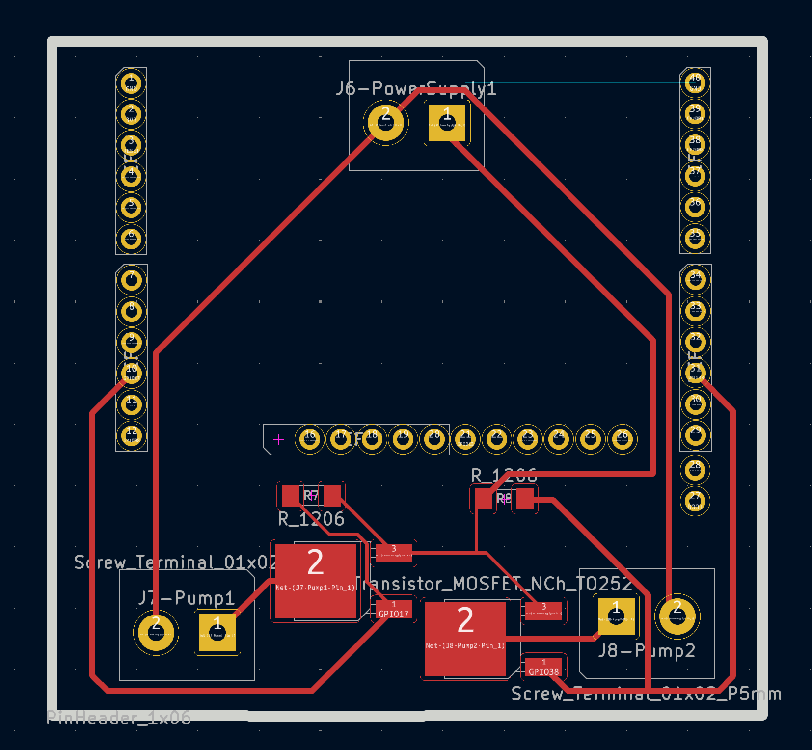
From the pump, the positive is connected to the V+ of the power supply and the GND is connected to the GND of the pin connector which connects to the Drain of the MOSFET.
SVG Preparation for Milling
To export the board as an SVG to be placed in Mods for file preparation, I exported three files, traces, holes, and outline. The traces include everything, the holes are the pin connectors, and the outline is the outer cut.
In Illustrator, I inverted the SVGs so that everything black = cut and white = keep
Since the traces will be connecting the external power supply, I made the traces wider (0.5mm).
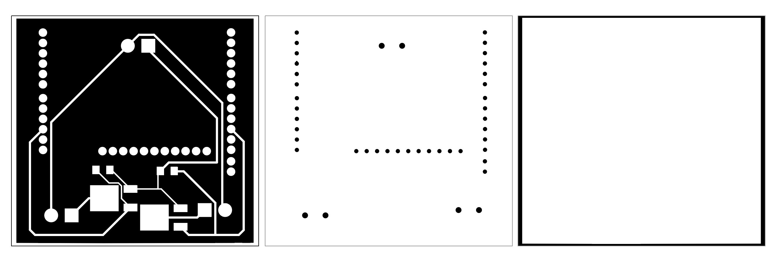
Export them as PNGs all the same size. My size is 58 x 55 mm so it can sit perfectly over the controller board. I used a scrap PCB, taped the back with double sided tape and placed it on the bed of the Roland SRM20. Make sure to sweep it up first because any minor differences in the level would be obvious when cutting the traces.
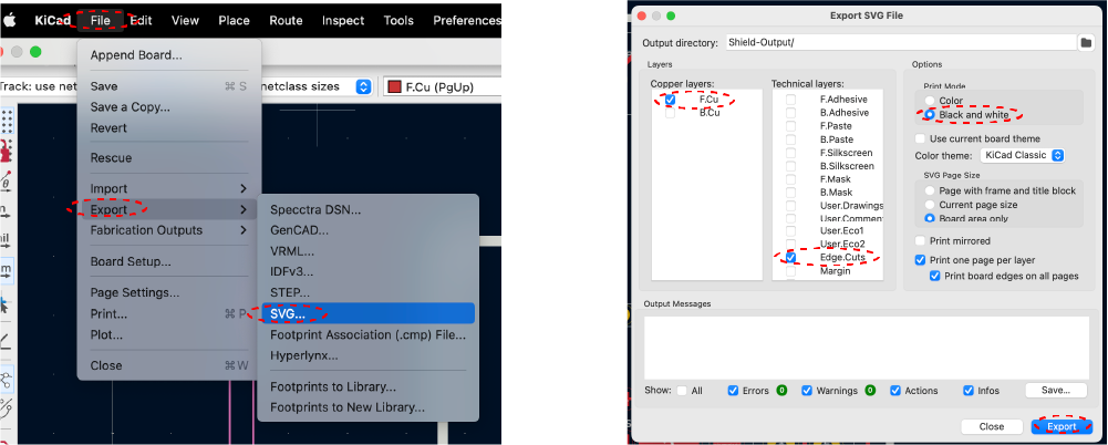
Mods
As shown in Week08 - Electronics Production, I used mods to create the files for the milling.
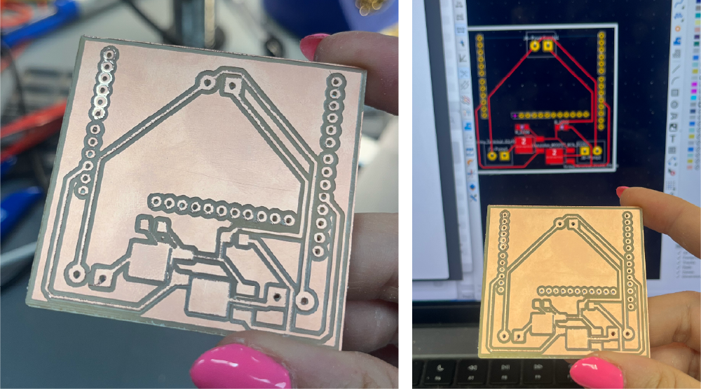
Milling
As shown in Week06 - Electronics Design, I set the machine up for homing and milling.
Soldering
Components:
- Mosfet 50V 16A
- Mosfet 50V 16A
- 2pin connectors 5mm
- 2pin connectors 5mm
- 2pin connectors 5mm
- 10kOhm
- 10kOhm
- Male Connectors
- 0Ohm Resistor
Continuity
Before plugging it in, I checked continuity to make sure that everything is soldered correctly. I realized that there was a missing trace, the GND of the power supply and the mictronctroller were not connected. I connected the GND pin connector to the copper of the board and then added a jumper resistor to the GND of the power supply.
Pumps
To connect the pumps to the output board, I connected the negative of the pump to the GND of the power supply which is connected to the GND of the board. Then the positive of the pump is connected to the MOSFET.

I switched the connections to connect the GND of the pumps to the output board and the Voltage to the power supply.
Re-milling
While testing the board, it was found that the pin headers used were not stable making the connections all unstable to the main micrrocontroller board. I redesigned the board and milled it again with different pinheads that have alternating ends so the pads are on top and not through the board. I also changed the second mosfet pin to be GPIO36 not 38 as the LED is already connected on 38.
In this iteration, the board was much cleaner, the milling was more precise as it was a new end mill. The soldering was also better and the same connectors were used for uniformity.
Test Code
The code is to turn on and off the pumps to test if everything is connected properly.
#define PUMP1_PIN  17  // GPIO17 pin connected to the MOSFET controlling pump 1
#define PUMP2_PIN  36  // GPIO36 pin connected to the MOSFET controlling pump 2

void setup() {
  pinMode(PUMP1_PIN, OUTPUT); // Set pump 1 pin as output
  pinMode(PUMP2_PIN, OUTPUT); // Set pump 2 pin as output
}

void loop() {
  // Turn on pump 1
  digitalWrite(PUMP1_PIN, HIGH);
  delay(5000); // Keep pump 1 on for 5 seconds

  // Turn off pump 1
  digitalWrite(PUMP1_PIN, LOW);

  // Wait for a brief period between pumps
  delay(1000); // 1 second delay before turning on the next pump

  // Turn on pump 2
  digitalWrite(PUMP2_PIN, HIGH);
  delay(5000); // Keep pump 2 on for 5 seconds

  // Turn off pump 2
  digitalWrite(PUMP2_PIN, LOW);

  // Wait for a brief period before repeating the loop
  delay(1000); // 1 second delay before starting over
}
Pumps working according to the code above connected to the output board: