4. Computer controlled cutting
Laser and vinyl cutting
After having 2 weeks building up the base this week was the first hands on experience in the fab Academy. This week we start to learn how to use the 2D CAD tools that we practiced with in pervious week to make a physical design. I had the experience of using laser cutting machines before so this week I tried to remind myself what I know and get familiar with the specific machines that we have in the lab.
What I learned
- The chain of action to turn on the laser cutting machines
- How to clean the mirrors and the lenses of the laser cutter.
- How is the interface of the machine connected to Rhino
- How to set the zero of the machine
- How to turn on the vinyl Cutter
- How to feed the vinyl in to the machine
- How to set the dim of the sheet
- How to adjust the cutter head to get a clean cut
- Placing the design in the machine interface software
- Hard part
Workshop
We kick off the week with a workshop to get familiar to machines in the house how to use them, the safety procedures and general rules. After that we got a chance to run some sample file and practice.
vinyl cutter
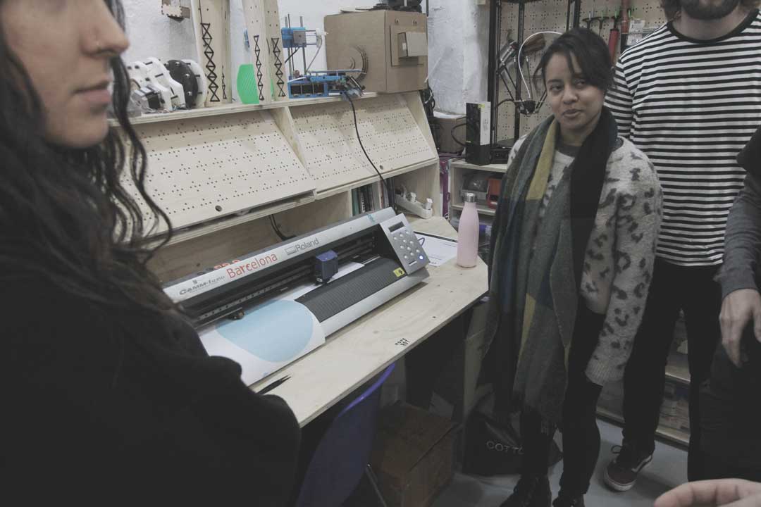
Fig01-introduction
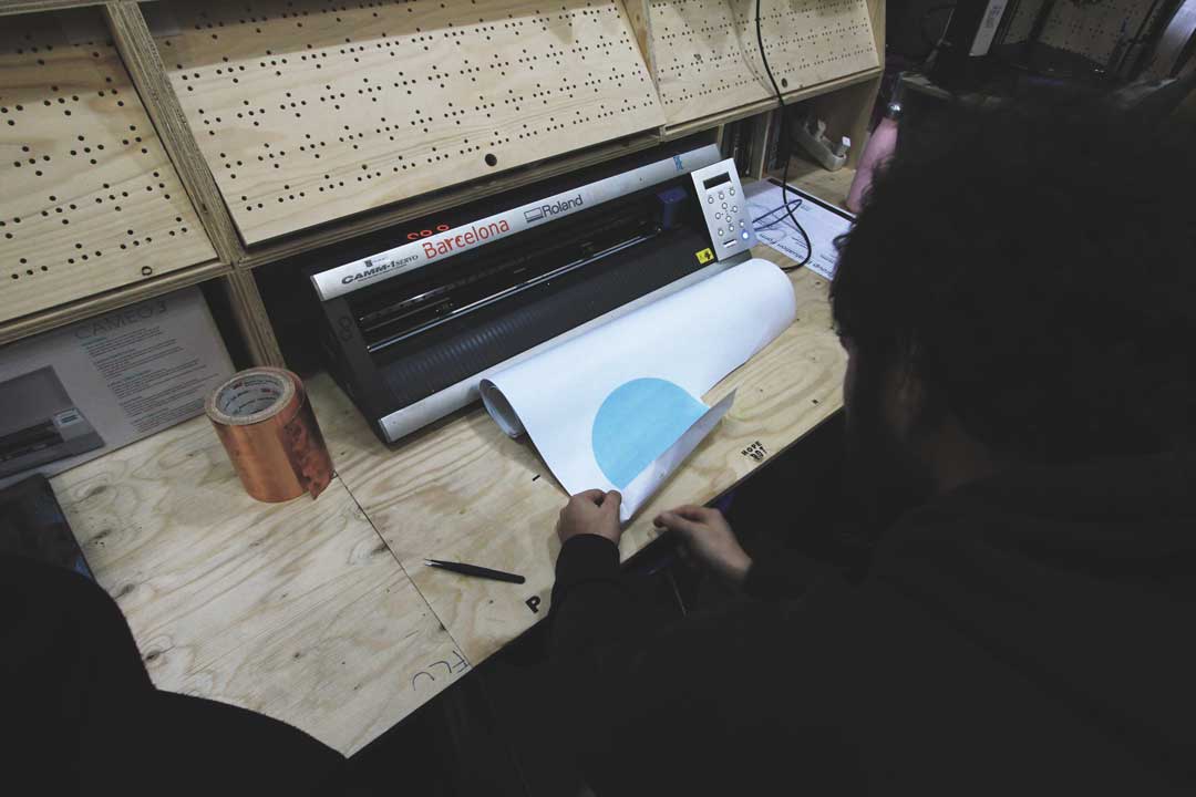
Fig02-Blad calibration
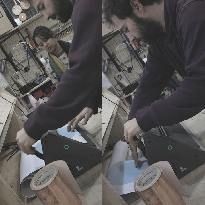
Fig03-Loading Vinyl
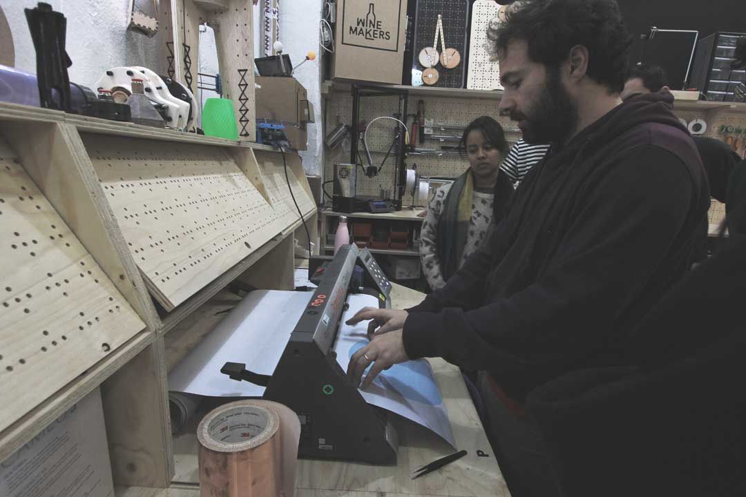
Fig04-Setting the shit size
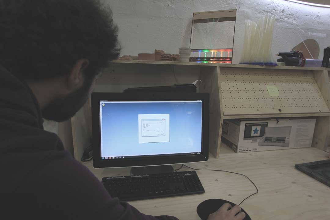
Fig05-Put the size into software
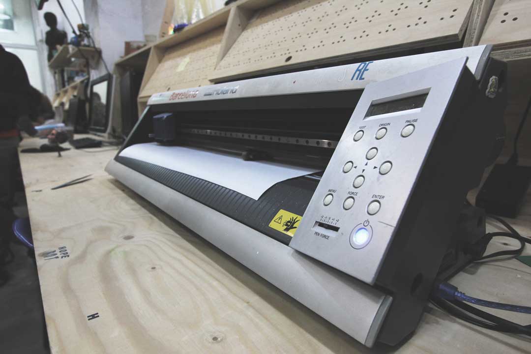
Fig06-The vinyl Cutter
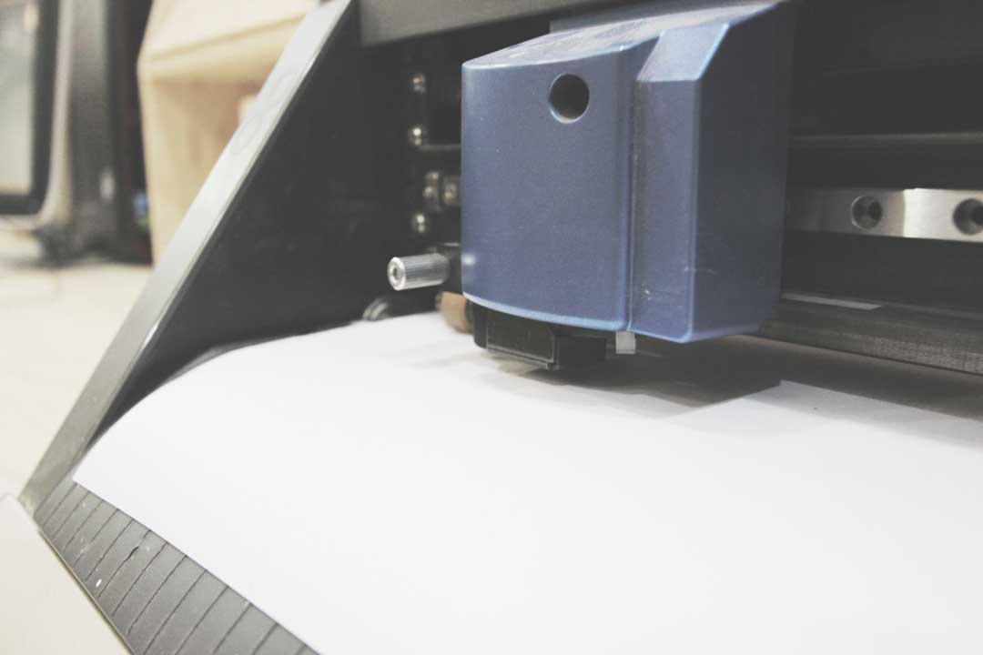
Fig07- The head of Cutter
Laser cutter
!
My experience
Group assignments
As group we test the tolerance between design and the cut part in the TROTEC SPEEDY 100. At first I found a file online and we tried with that. It was not a successful test. because we tried the recommended setting for Cardboard on plywood. To solve this issue I designed a parametric model where I can select the material type and length and it will generate the test file automatically. you can follow up our works in my team mate pages.
Through this test I understood the triangle relation between Speed , power, and frequency. There are certain margins of this values that depends on the material but to achieve a perfect cut and minimize the kerf we had to play with this parameters. Because not all the material are the same also some factors from the machine also could be effect the performance of the cut. By adjusting this parameters we can overcome this small tolerances.
Laser cutting
I start with the design of a simple kit with the different shapes of node to experiment with the press fit joinery. I made the a parametric design with the grasshopper.
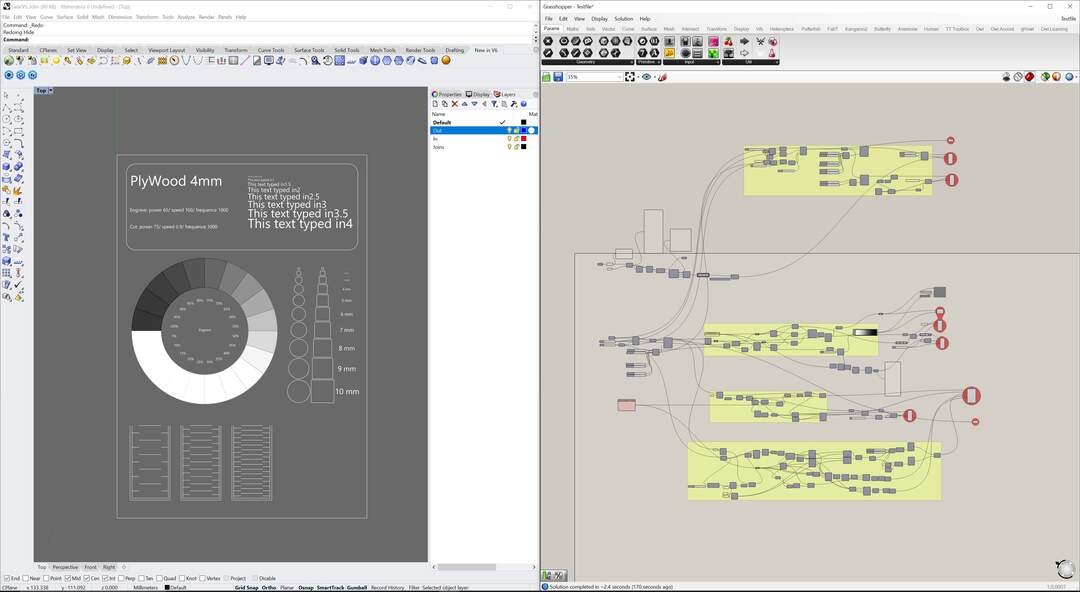
Fig011-TestFile Generator with grasshopper

Fig012- Hilbert Curve For Bending
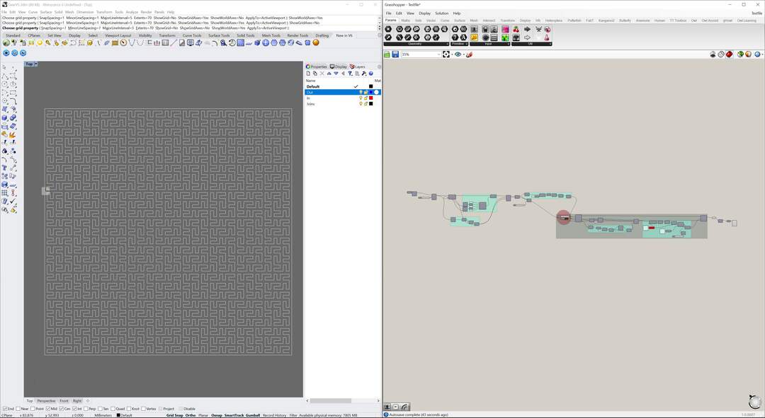
Fig013- Peano Curve For Bending
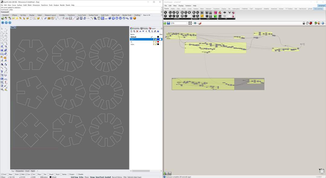
Fig014-Kit Generator
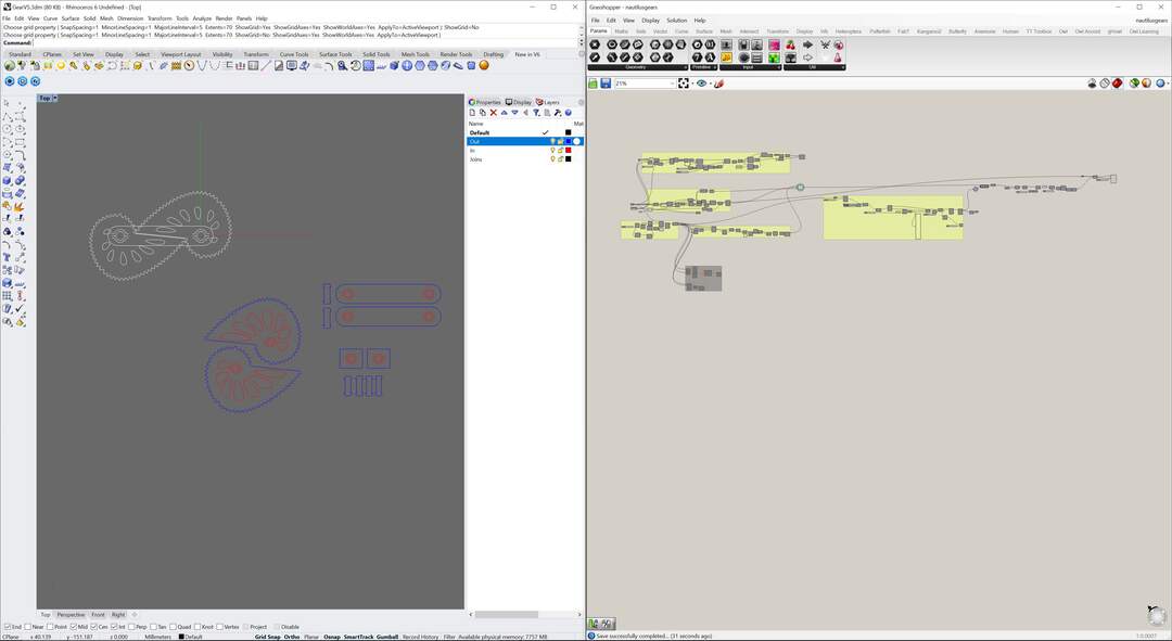
Fig015- nautilus Gear
After that I developed a modular algorithm to generate sample files for different materials base on a data sheet which providing the settings for laser cutting each material with different thickness.
material dataset
I should mention that the plastic base material putted a side cause of environmental impacts. And most of the material used for this practice has been recycled from other projects in the house.
| M | T | EP | ES | EF | CP | CS | CF |
|---|---|---|---|---|---|---|---|
| Cardboard | 3 | 60 | 100 | 1000 | 30 | 1 | 1000 |
| Cardboard | 4 | 60 | 100 | 1000 | 40 | 1 | 1000 |
| Cardboard | 5 | 70 | 100 | 1000 | 55 | 1 | 1000 |
| HighDCardboard | 2 | 60 | 100 | 1000 | 40 | 1 | 1000 |
| HighDCardboard | 3 | 70 | 100 | 1000 | 90 | 1 | 1000 |
| PlyWood | 3 | 60 | 100 | 1000 | 60 | 1.5 | 1000 |
| PlyWood | 4 | 65 | 100 | 1000 | 75 | 0.9 | 1000 |
| PlyWood | 5 | 70 | 100 | 1000 | 80 | 0.8 | 1000 |
Cleaning the laser lenses
At the beginning of working with Laser cut I had this chance to witness the cleaning and maintaining process of the mirror and lens by lab manager. It was very sensitive piece of optic that it need extra cautious for cleaning to avoid any damage to it. He was using a pure solution of acetone with a Nano fabric. The trick is to drop acetone on the lenses and slide the fabric on it to remove the dirt and haze of fume from the lenses.
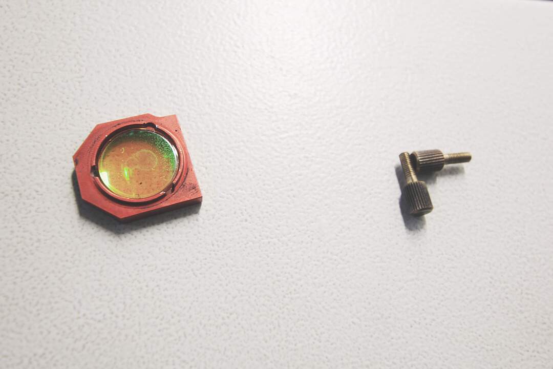 Fig01- Cleaning the lens and mirror by lab manager
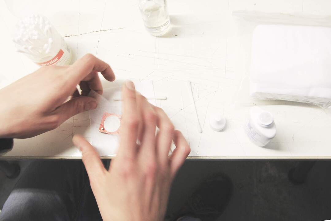 Fig01- Cleaning the lens and mirror by lab manager
After setting Everything up we start with measuring the stock and focusing the laser for cutting the test. When the test was finished and the laser parameters are measured, I input the values in my code in order to adapt the design to the parameters. The other day base on those parameters I continued the production.
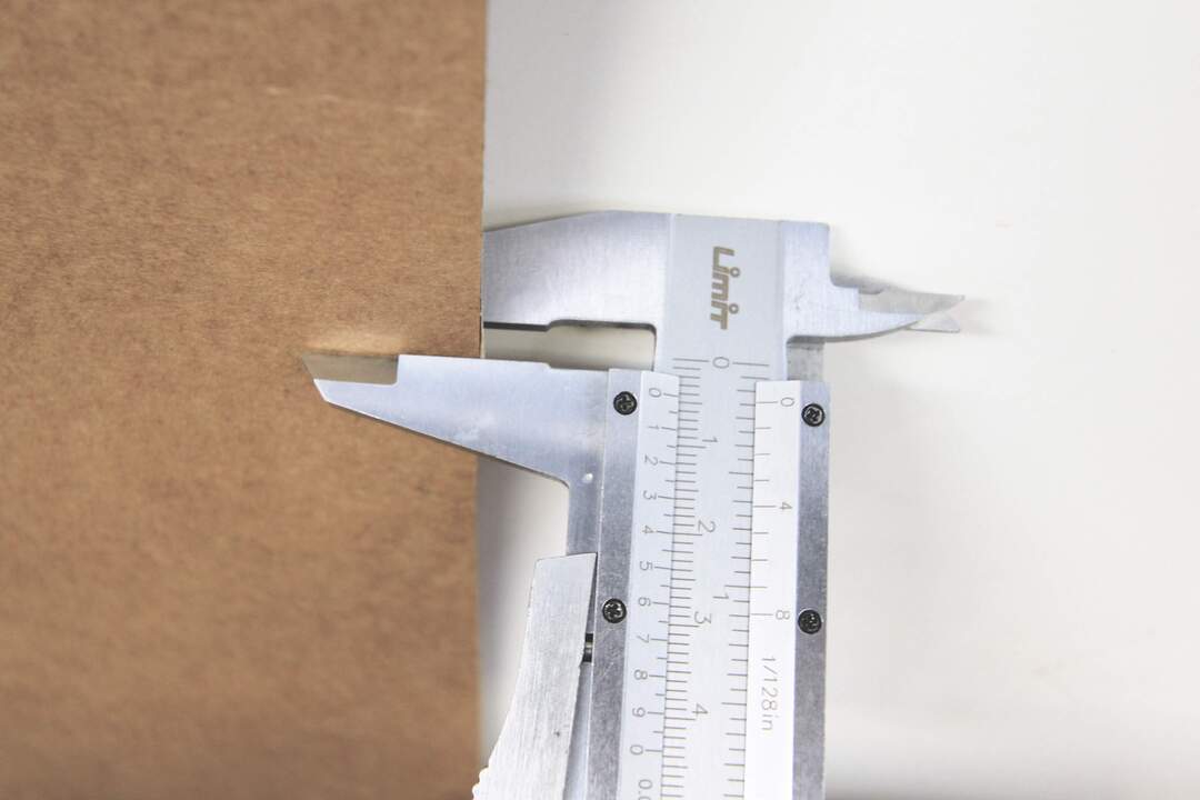 Fig03- measuring stock
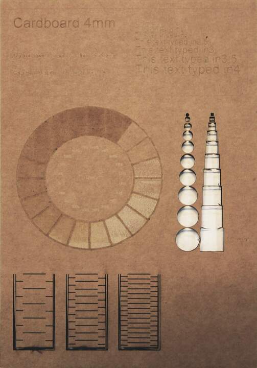 Fig09- Cardboard test
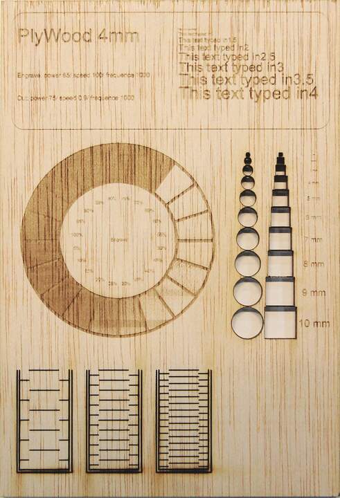 Fig10- Plywood test
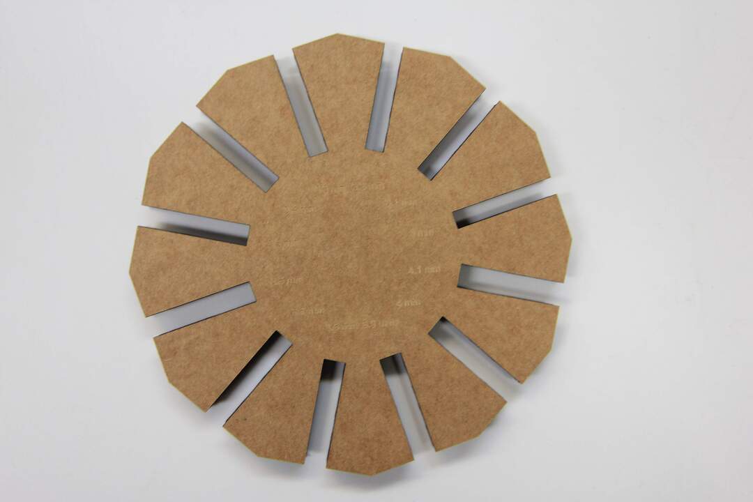 Fig04- press fit joinery test
So for this test I have tested the range between 3-4.1mm to see which one is working the best with the 4mm Cardboard. I agree I did not needed to test to small but I wanted to know how much smaller it can be to get the max pressure for locking the pieces. At the end 3.8 was the best although I could push through pieces in 3.6 joins but it was starting ruining the structural property of the cardboard.
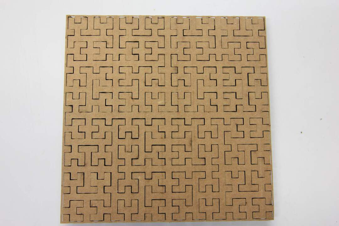 Fig05- Peano curve cut
Fig05- Hilbert curve cut>
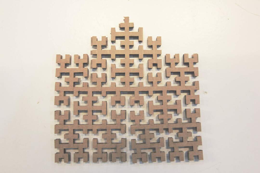 Fig06- Unsuccessful material removal from model
I think this is not a good design to do with Cardboard. I will try it later with different material
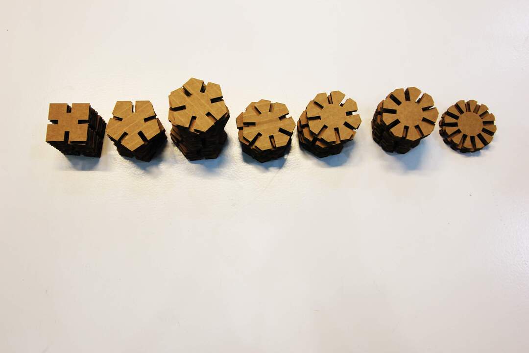 Fig07-Cleaning the lens and mirror by lab manager
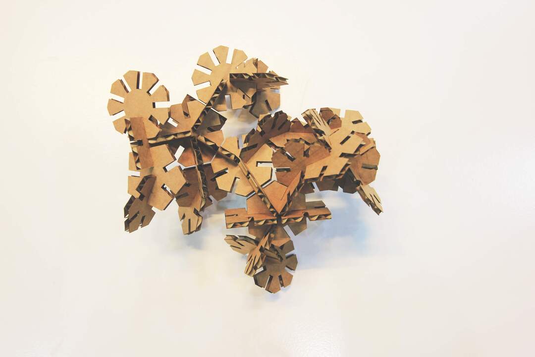 Fig08- Final assembly of the modules
!
I am trying to impediment the snap joinery with plywood Currently have not got any good result due to the size of my peace and fragility of the material. I think I need to adapt my design to a bigger size of this joinery.
Vinyl cutting
My main idea for vinyl cutting was to have a graphic design which can be divided to more than one layer and the difficulty of transfer each layer to the others. for this matter I traced an image of cicada with two different settings and made a 3 layer design to cut with the vinyl cutter. as you can see I was not that successful in doing it. I believe that I need a marker to keep track of the position of each layer. I probably try it in the following week.
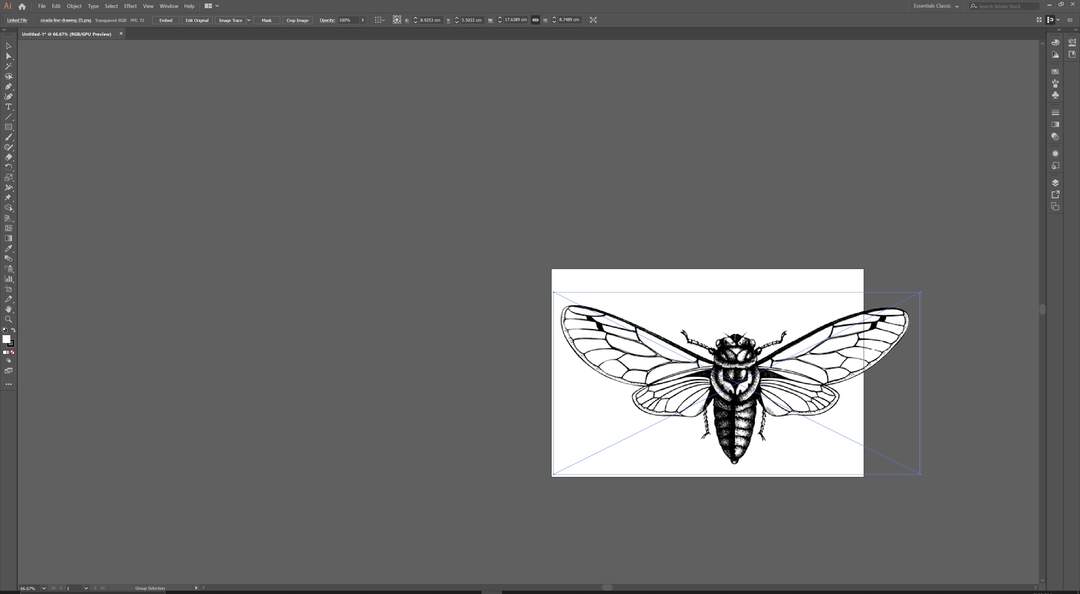 Fig09- Import image
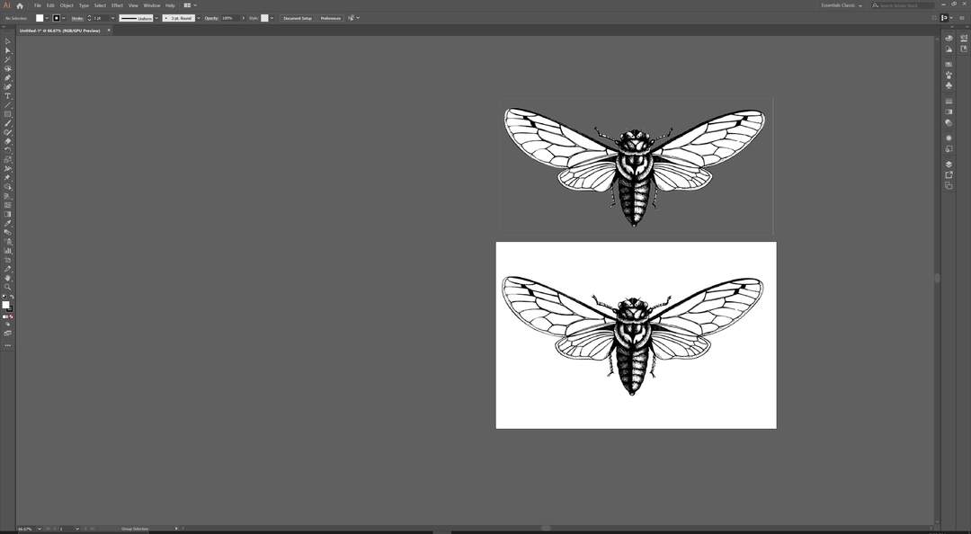 Fig10- Make Copy
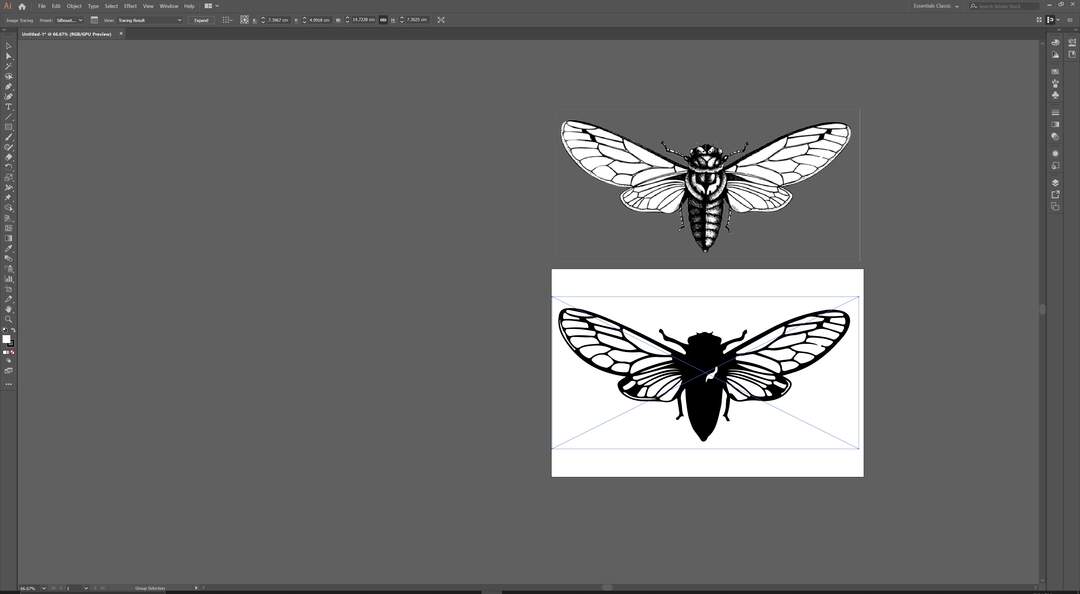 Fig10- Silhouette
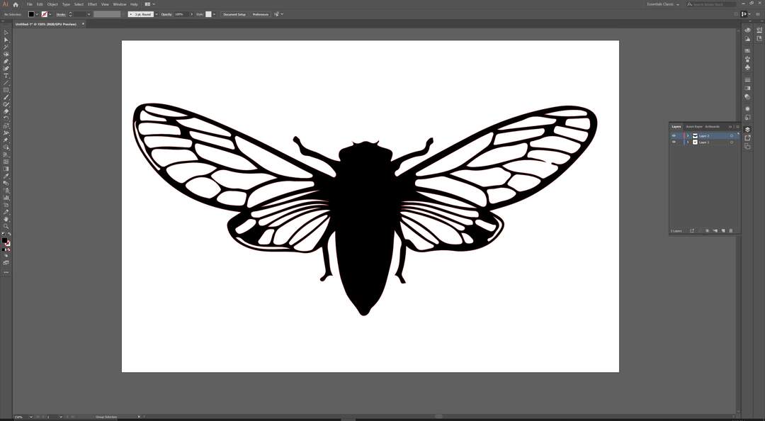 Fig12- Change Layer and Modify the vector
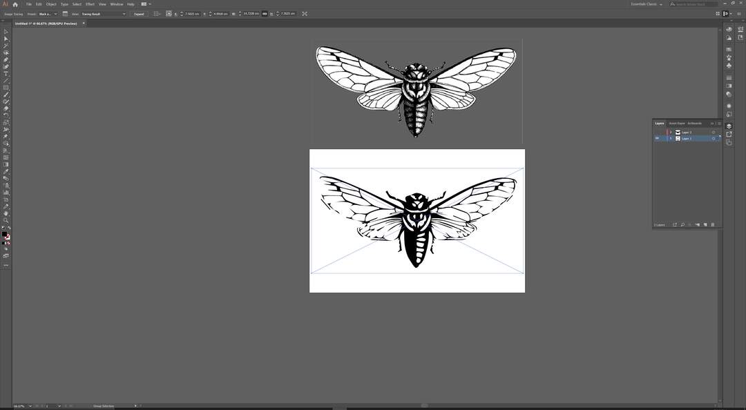 Fig13- Black and white Logo setting for image tracing
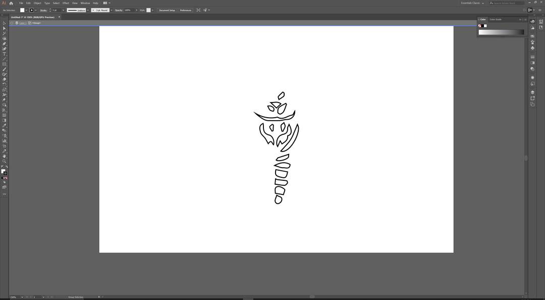 Fig14- Edit the outcome vector
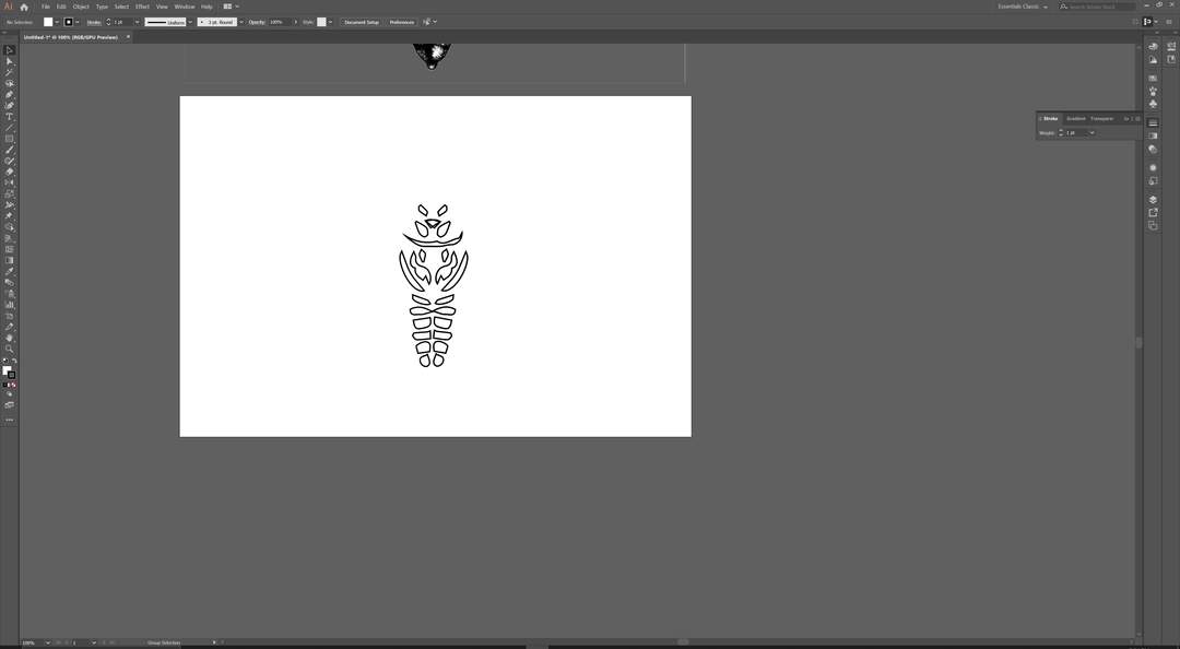 Fig15- Mirror the vectors
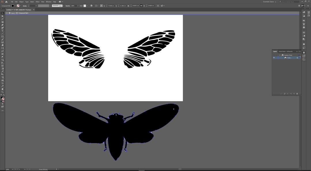 Fig16- Clean the silhouette to get the outer line
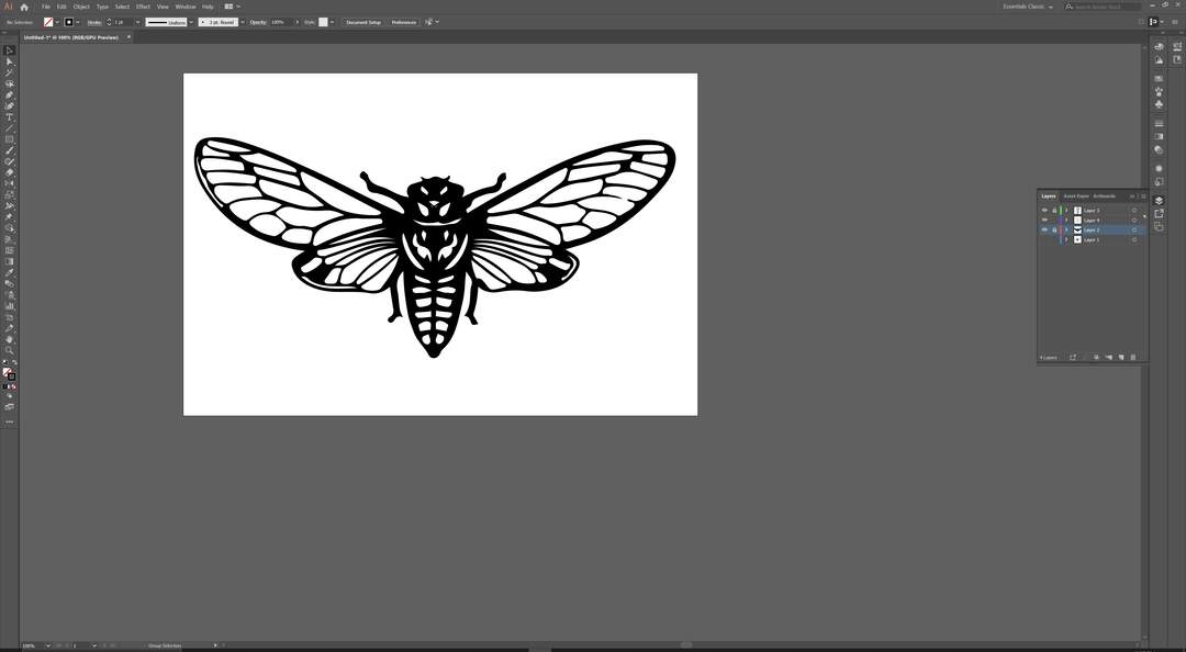 Fig17- Final design
For Cutting this design I have used the Roland CAMM-servo1 machine. At the first step I load the white role of vinyl to the machine and setup the origin. Then in the software I get the size of the stock that machine read during the previous stage. Based on this numbers it will update the workspace of the artwork so I can place my design according to the stock. after this I run couple of test to adjust speed of cutting and the blade. When I made sure that Everything is fine I send my design to be cut. The computer communicate with machine through a serial usb port and sending the commands through this link. The speed for this work was 5cm/s and the force was 150g.
You can follow up the process of cutting in the video section.
 Fig17- Final Outcome
Video
You can follow the process in the following Video.
- Laser
- Vinyl
Files
All the files available in the following link!
Final project Contribution
In my final project I used laser and vinyl cutting in most of the parts of my project. I have used laser cut to make 3 layer acrylic. there are 2 new technique that I implemented those are pocketing and double-side laser cutting.