10. input devices
Sensors / Digital and analog read
Aims
The sensor that I chose to work with is the capacitive sensing. I really fascinated by the simplicity of the system and complexity of the applications. I would like to develop a touch interface embedded in my final project as the interface of the machine. I would try to push this week to finish at least the design of the board.
Group assignment
For this group assignment since we did not have access to oscilloscopes, I just measure the voltage change from the digital and analog pin of Arduino. As you can see in the videos there is not much difference between them since both will reach 5V anyway. I think the timing in the reads from the multimeter also is not that accurate.
I can see some difference between the noises but it is not obvious. There are different voltages appearing for analog however in digital the numbers are always same(almost).
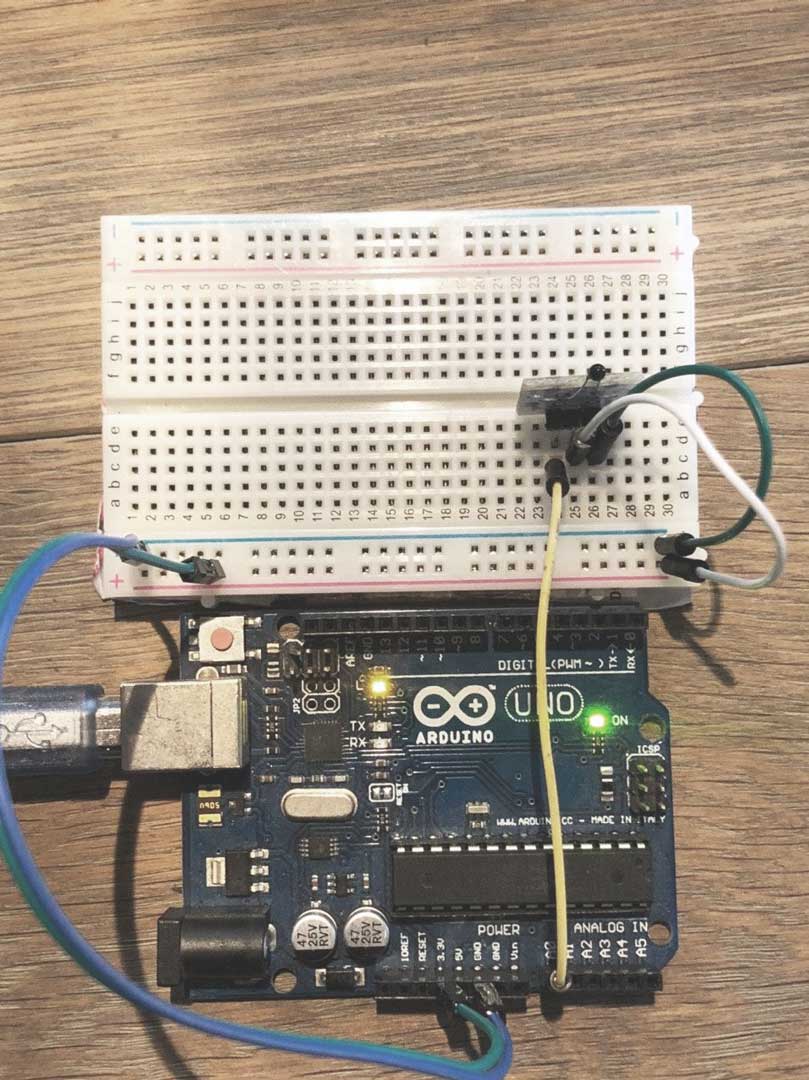
Digital read
I tried the analog read with a switch and resistor. basically it shows if the voltage is connected or not.
int pin = 7;
unsigned long duration;

void setup() {
  Serial.begin(9600);
  pinMode(pin, INPUT);
}

void loop() {
  duration = pulseIn(pin, HIGH);
  Serial.println(duration);
}
Analog read
For analog read I tried the temperature sensor which was giving me some resistance number but in order to translate that to the temperature I had to look up to the formula for the conversion.
int ThermistorPin = A0;
int Vo;
float R1 = 10000;
float logR2, R2, T;
float c1 = 1.009249522e-03, c2 = 2.378405444e-04, c3 = 2.019202697e-07;

void setup() {
Serial.begin(9600);
}

void loop() {

  Vo = analogRead(ThermistorPin);
  R2 = R1 * (1023.0 / (float)Vo - 1.0);
  logR2 = log(R2);
  T = (1.0 / (c1 + c2*logR2 + c3*logR2*logR2*logR2));
  T = T - 273.15;
  T = (T * 9.0)/ 5.0 + 32.0;
  float Tconv = 0.0;
  Tconv = (T-32)*(0.5);
  Serial.print("Temperature: ");
  Serial.print(Tconv);
  Serial.println(" C");

  delay(500);
}
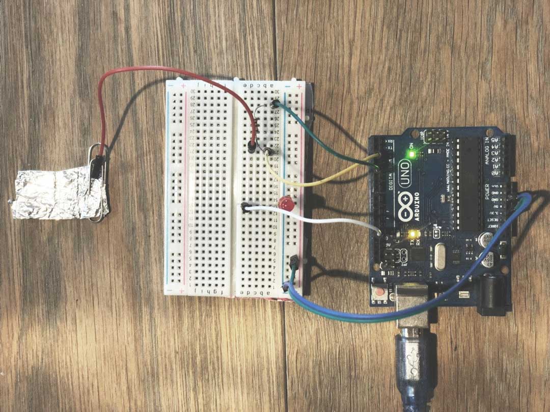
capacitive Sensor
I think this sensor is one of the most easiest to build also the most applicable one. I have planned to build the interface of my final project with this Sensor.
#include <CapacitiveSensor.h>
CapacitiveSensor touchSwitch = CapacitiveSensor(4, 2);
int LEDpin = 13;

void setup()
{
 pinMode(LEDpin, OUTPUT);
 Serial.begin(9600);
}

void loop()
{
 long start = millis();
 long val = touchSwitch.capacitiveSensor(30);
if (val > 100) {
 digitalWrite(LEDpin, HIGH);
 } else {
 digitalWrite(LEDpin, LOW);
 }
 Serial.println(val);
}
circuit
After successful trying capacitive sensing, I start design a board for touch pad base on two project that Neil showed in the class. - Touch pad - Multi Touch
At first I needed to understand the step respond concept. What I got is that with this technique we can measure the fluctuation of electron charges on a conductive material. The base module of circuit is very simple. We need to pull up the material voltage and read the change of charges from it.
               ________
step          |        |
---/\/\/\/\---|        |---Sense
      R       |________|
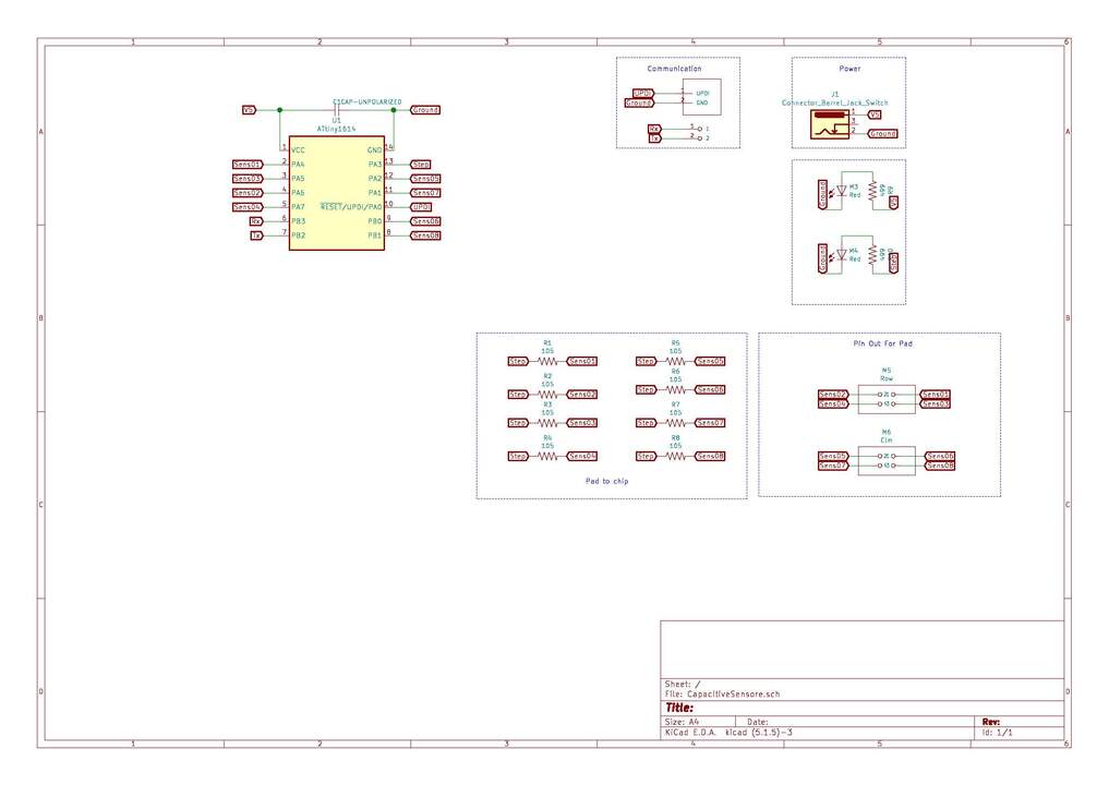
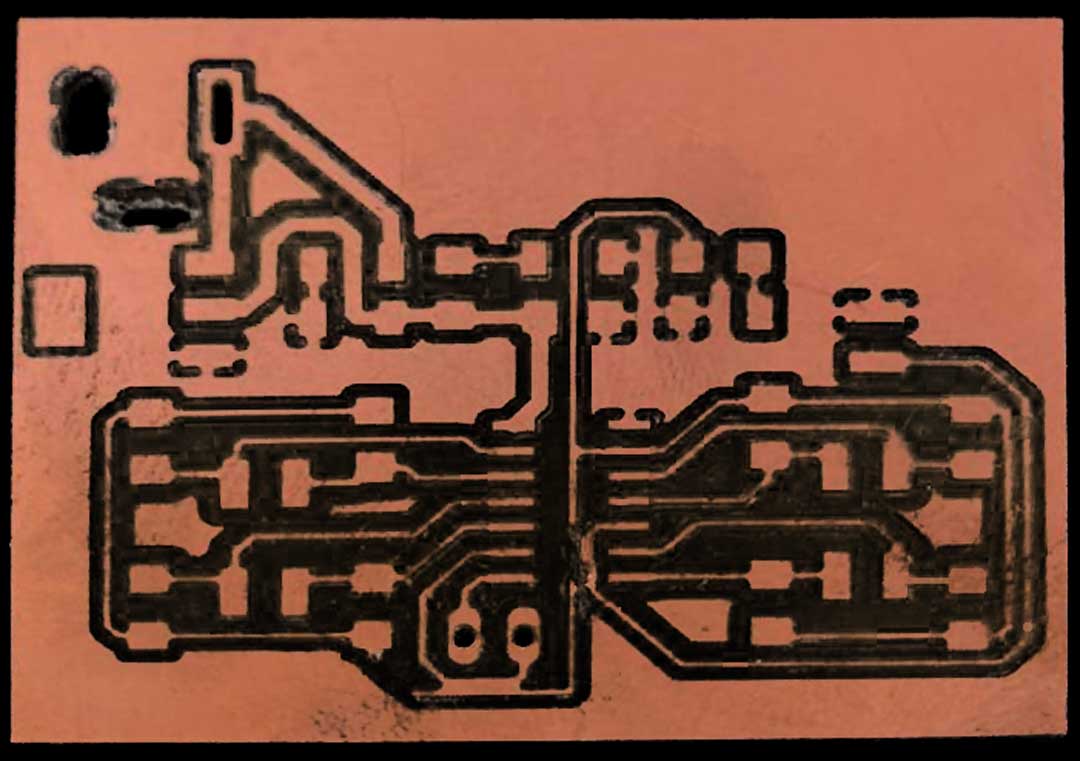
Design
For designing a board for the touch pad I have decided to use Attiny1614 chip since it has enough pin to support the pad reads and interface with it is new. I am using UPDI protocol to flash the board and there is a external out put for the serial communication. Two led added one for power check and the other for testing the chip.
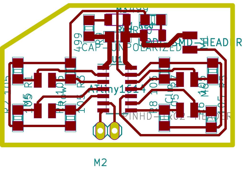
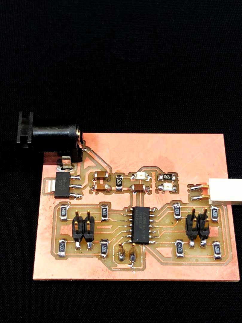
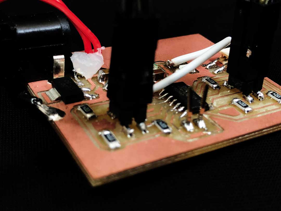
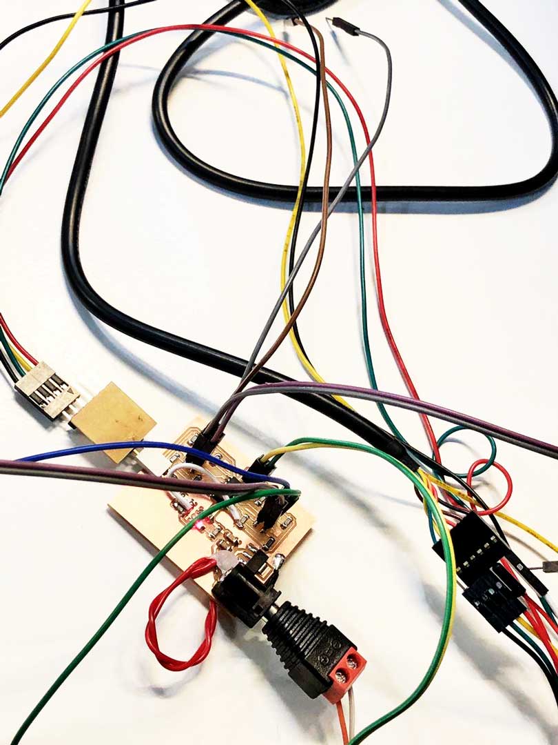
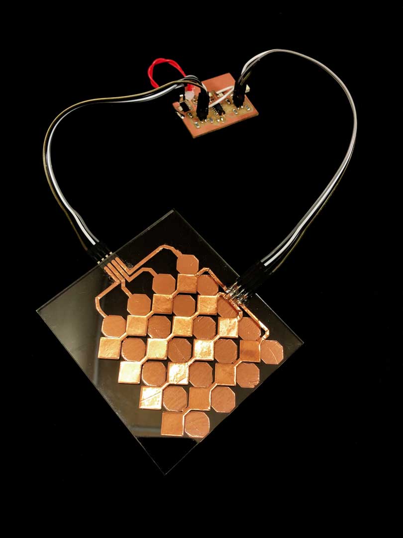
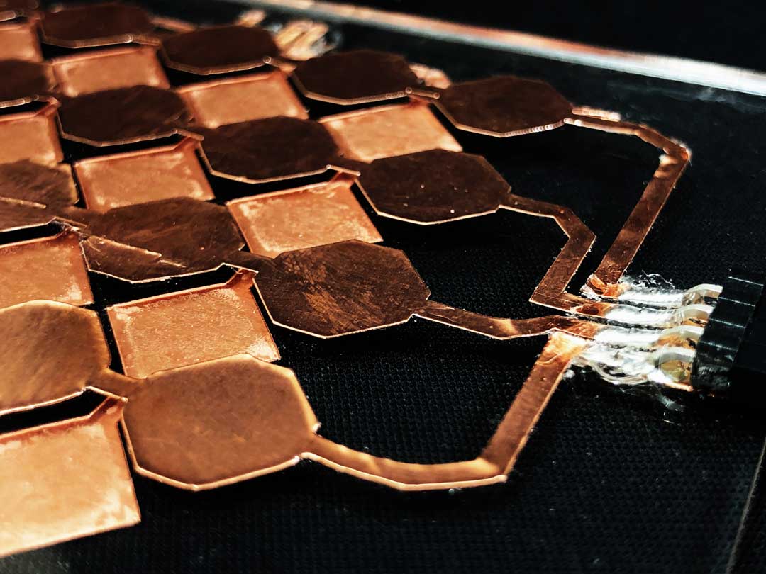
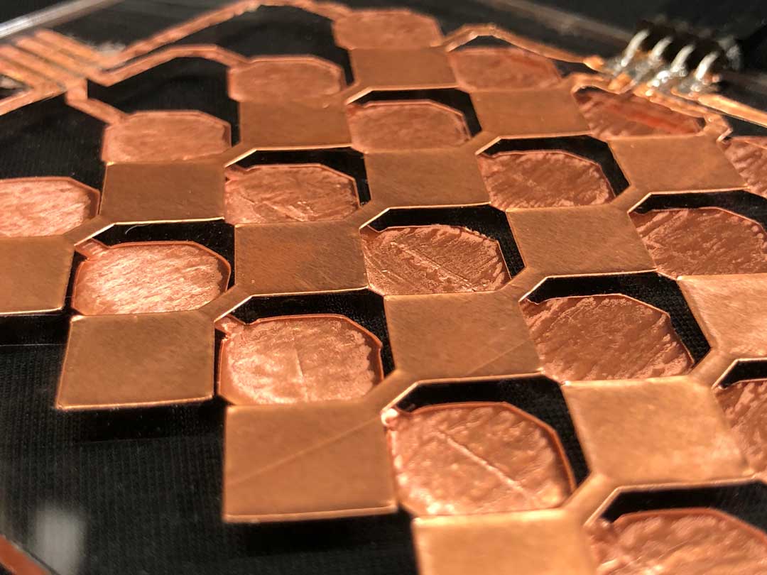
PCB / Pad
The PCB production was quit simple. But some mistakes happened a long it that I addressed it with wire jumper. First, was the step trace under the IC that had a collision with on of the leg traces which I need to cut off and connected with the wire(White wire in the picture). The other problem was in the power jack. At the first place I should have flipped it and connected from the other side. Also I did a mistake in making file in mode for the holes and import the invert of the file. I realized it in the first hole and re-made the file for the rest. At the end as you can see in the pictures I had to add wire to make sure the power reaching to the board. Furthermore, I had hot glue beside of the jack to make it steady on the board while connection and disconnection. The other part that I will think to alter is the terminal for the serial port. In the pad, I laser cut a piece of acrylic to transfer the vinyl cut pattern on it. The vinyl cutting was easy with the silhouette cameo.The setting has been set on the speed 2 and force 5 in the silhouette studio.
code
I think the code will be in 2 part, one for the chip and reading the values and sending them through the serial port and the other part will be the interface of the readings. For the interface I was checking Neil’s codes and I think to use python one for reading the values. since it is much understandable for me and also I want to try a python base interface.
Microcontroller code
#include <CapacitiveSensor.h>

#define _step A3
#define sens5 A2
#define sens7 A1
#define sens6 B0
#define sens8 B1
#define sens4 A7
#define sens2 A6
#define sens3 A5
#define sens1 A4

CapacitiveSensor   cs_1 = CapacitiveSensor(_step,sens1);
CapacitiveSensor   cs_2 = CapacitiveSensor(_step,sens2);
CapacitiveSensor   cs_3 = CapacitiveSensor(_step,sens3);
CapacitiveSensor   cs_4 = CapacitiveSensor(_step,sens4);
CapacitiveSensor   cs_5 = CapacitiveSensor(_step,sens5);
CapacitiveSensor   cs_6 = CapacitiveSensor(_step,sens6);
CapacitiveSensor   cs_7 = CapacitiveSensor(_step,sens7);
CapacitiveSensor   cs_8 = CapacitiveSensor(_step,sens8);


void setup() {
  // put your setup code here, to run once:
  Serial.begin(115200);
}

void loop() {
  // put your main code here, to run repeatedly:
  for (int i = 1 ; i<=8; i++){
    long s = cs_1.capacitiveSensor(30);
    Serial.print(i);
    Serial.print(" : ");
    Serial.println(s);
  }
  delay(10);

}
GUI code (current state; not done yet!)
import serial
import os
import time
#import pygame

#pygame.init()
#Color
white = (255, 255, 255)
black = (0,0,0)
gray = (180,180,180)
blue = (0,0,255)
red = (255,0,0)

port = os.popen('python -m serial.tools.list_ports').read()

def set_display(dis_width = 720,dis_height = 480):
    dis = pygame.display.set_mode((dis_width,dis_height))
    pygame.display.update()
    pygame.display.set_caption('TouchPad')

'''def grid(col=4 ,row=4):
    for i in range(col):
        for j in range(row):'''


def touch_read(ask = False):
    with serial.Serial(port) as ser:
        ser.baudrate = 115200
        while True:
            x =  ser.readline()
            num = int(x)
            if ask:
                return num


def main():
    time_now = lambda: int(round(time.time() * 1000))
    start_time = time_now()
    while True:
        if start_time-time_now() > 100:
            val = touch_read(ask=True)
            print(val)


if __name__ == '__main__':
    main()
More advance practice could be adding a gesture detection to this system which will make it very interesting but I guess it would be over kill for this assignment. Also still needs to finish the GUI but anyway I put the current stage of my progress.
File
You can download the files of this project from following link.