8. Computer controlled machine
CAM and CNC
Aims
I have experience with CAM and CNC machine. This week I will try to join someone to make something big. Also If I finish the 3d model of my final project maybe I can produce the foundation of my vending machine. Since I am in quarantine and I have to work and study at home. I felt the necessity of having a desk where I can set up my working space. Also, I needed it to be something transformable to a flat board which can be easily stored.
Group assignment
We team up and tried the tolerance of the machine also the feed rate in different spindle speed.
the speed and feed rate that we tried for the softwood: - 0.28mm x 18,000rpm = 5,000mm/min - 0.3mm x 18,000rpm = 5,400mm/min - 0.33mm x 18,000rpm = 5,900mm/min - 0.28mm x 20,000rpm = 5,600mm/min - 0.3mm x 20,000rpm = 6,000mm/min - 0.33mm x 20,000rpm = 6,600mm/min
the end mill that we tried this with was 6mm 1 flute down-cutter.
you can follow up the extensive documentation on my teammate page.
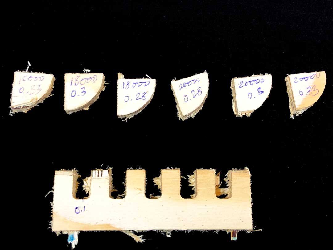
the final result of the test
my conclusion from the observation of this test is that if you want to make some thing clean you can go with a medium to high with the low feed rate. But if the machining time is important higher speed with the medium to high feed-rate can help to reduce the time a bit. However it might chip of the plywood.
CNC
subtracting manufacturing
The most available machine
The limitation is your imagination!
First prototype with other Technology then make your final design with CNC to make a manufacturing. laser cut carboard then go for CNC the plywood!
Press-fit joinery
5 axis CNC and machine center CNC
Parts of CNC - table - Cable carrier - Bridge - Spindle/routers(DC motors) - collet(clamp your end mill) - end mill
differ between routers
collet should get cleaned before putting the end milling.
end mills are varied in many different sizes and styles. they are not the same as the drill bits. they can cut vertical and horizontal
straight / up cut / Down cut / compression
flutes of the end mills are very important and the setting would change depends on the number of the flutes.
end mill coting
file setting
spindle speed 18-24 k rpm
feed rate
step Down
half diameter of the end mills
step over
chip load equation.
CNC are huge baby! trust your ears!
CAD design for CNC
I tried to first develop a code that can process the intersection of the elements and generate the joinery!
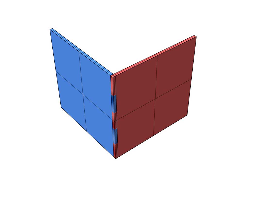
Fig01 - Corner to corner intersection
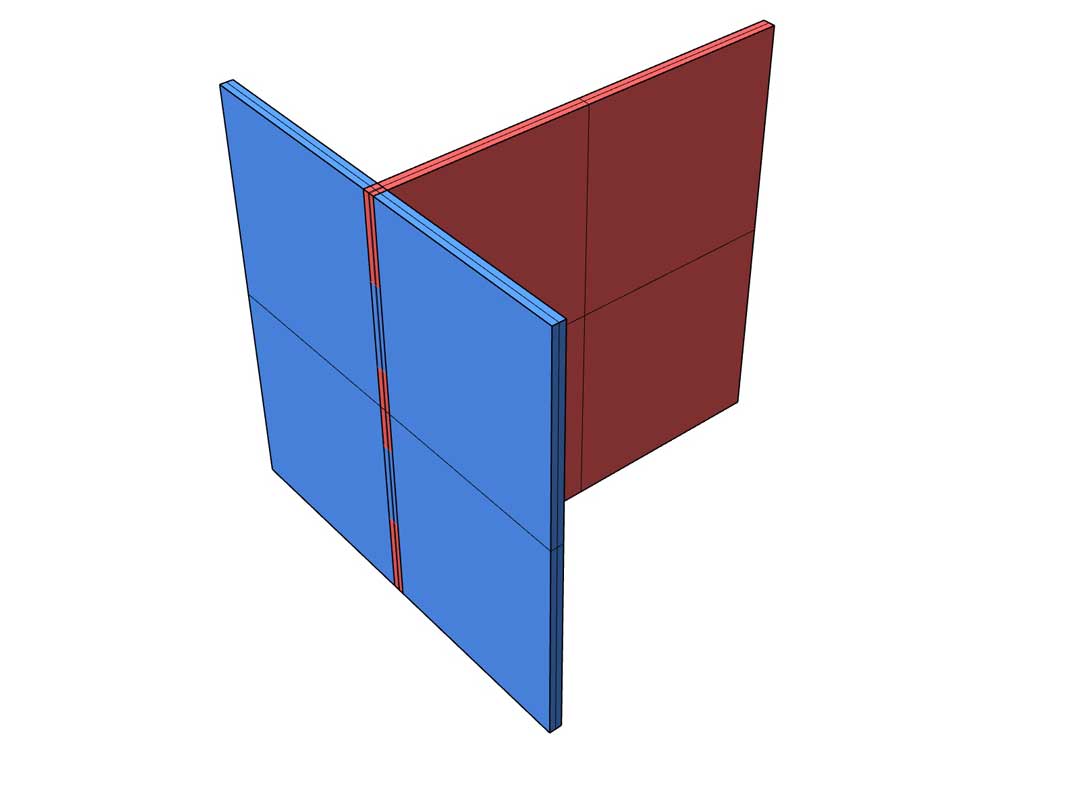
Fig02 - In the middle intersection
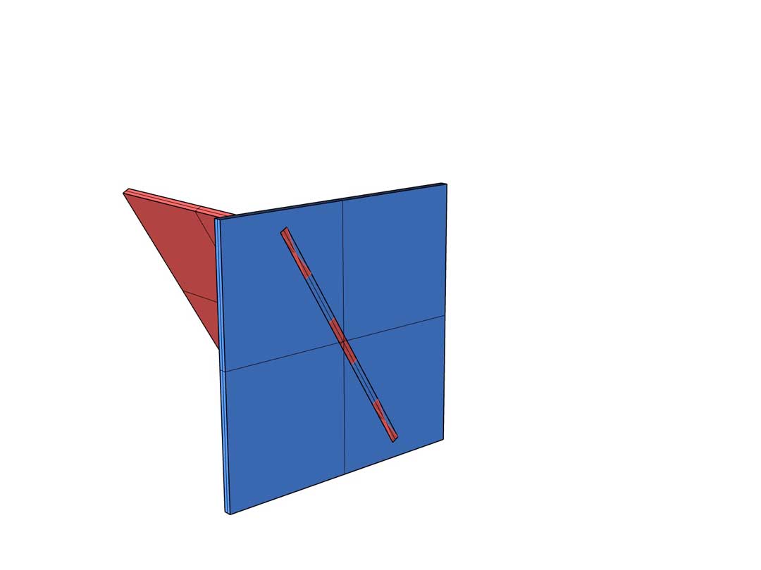
Fig03 - In angle intersection
Design a flat pack desk
My initial design concept was to make a desk that is easily assemble and disassemble. Also it is possible to pack it flat so it would be easy to store it. I start my design in grasshopper to make it parametric so I could play with the size of it. At the beginning, I define the overall size of the desk by making its bounding box. base on this box I define the legs’ outline and their conjunction. After that tried to build the 3d of the legs by considering the assembly. This led me to design the current joinery. later on I fix some collisions of the kinetic assembly of the legs simulating it digitally. The other adjustment that I added was the thickness of the material as a parameter. After those fixes, I start shaping the desktop from the initial box. I wanted to make sure that the legs not passing through the desk so I would have a nice flat desktop. later I realize that I need to add a hole in the middle of the desk to pass the wire since I always working with laptop. At the end I orient the legs to the desktop plane and place them in a way that could fit inside of the desk. Due to some issue with Boolean operation in grasshopper and fillet function, I post-produced the design file in rhino to prepper the file for fabrication. In this process I added a fillet to the edges with the radios of 3mm (half the milling bit dim) so we would not get the fitting problem. Although at end I forgot to offset the lines to consider for tolerance. In the next iteration of the design this step has been considered. In the following you can see the steps of the design.
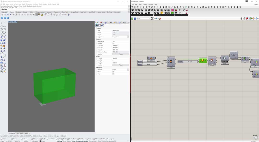
Fig01- Define the bounding box
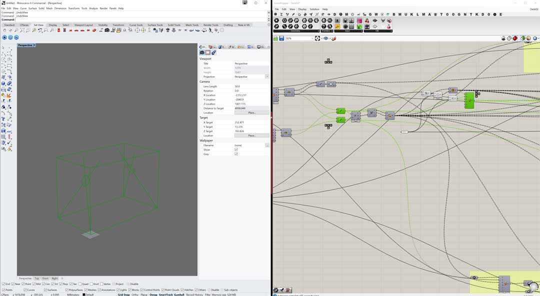
Fig02- Outline the skeleton of the table
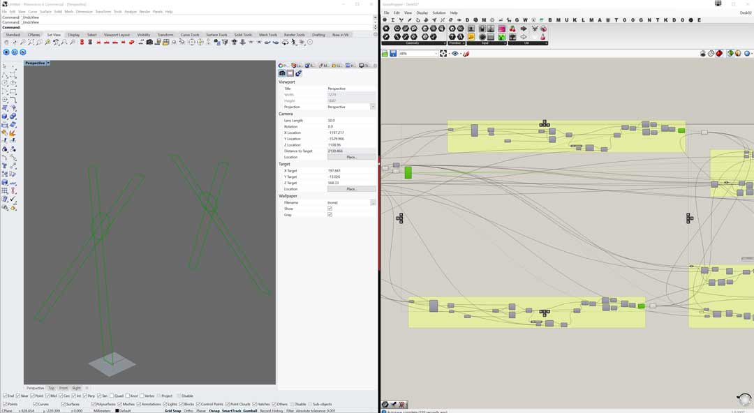
Fig03- Forming the leg out line and their joinery
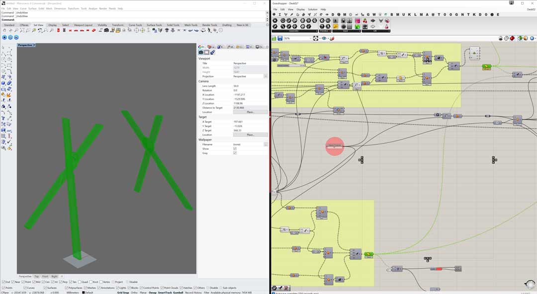
Fig04- shape the legs with joinery detail
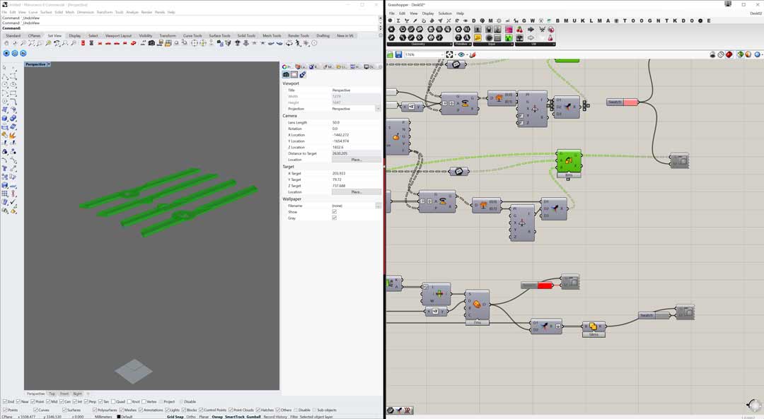
Fig05- orient the leg under the table
The final result of the design
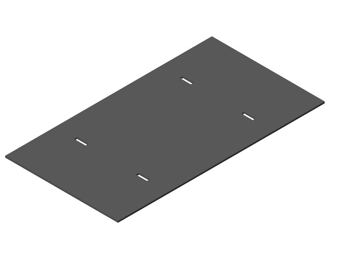
Fig01- Top of the desk joinery
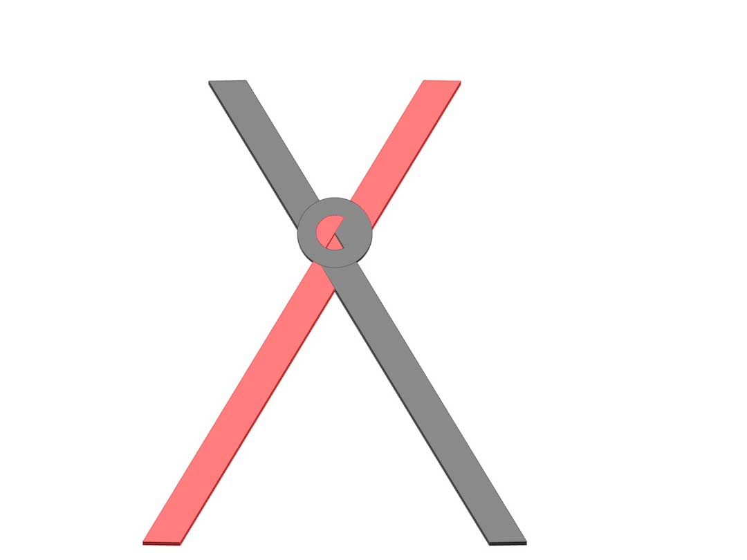
Fig02- Leg joinery
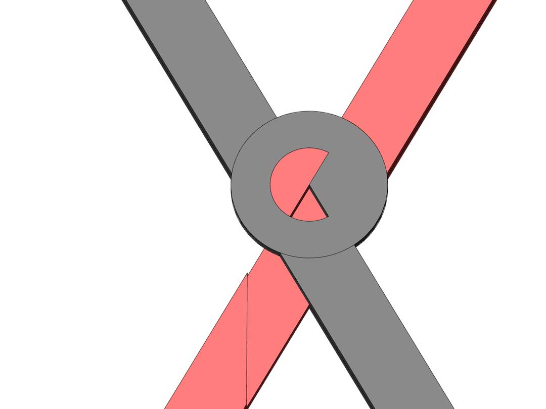
Fig03- Leg joinery detail
Fig04- Leg joinery assembly
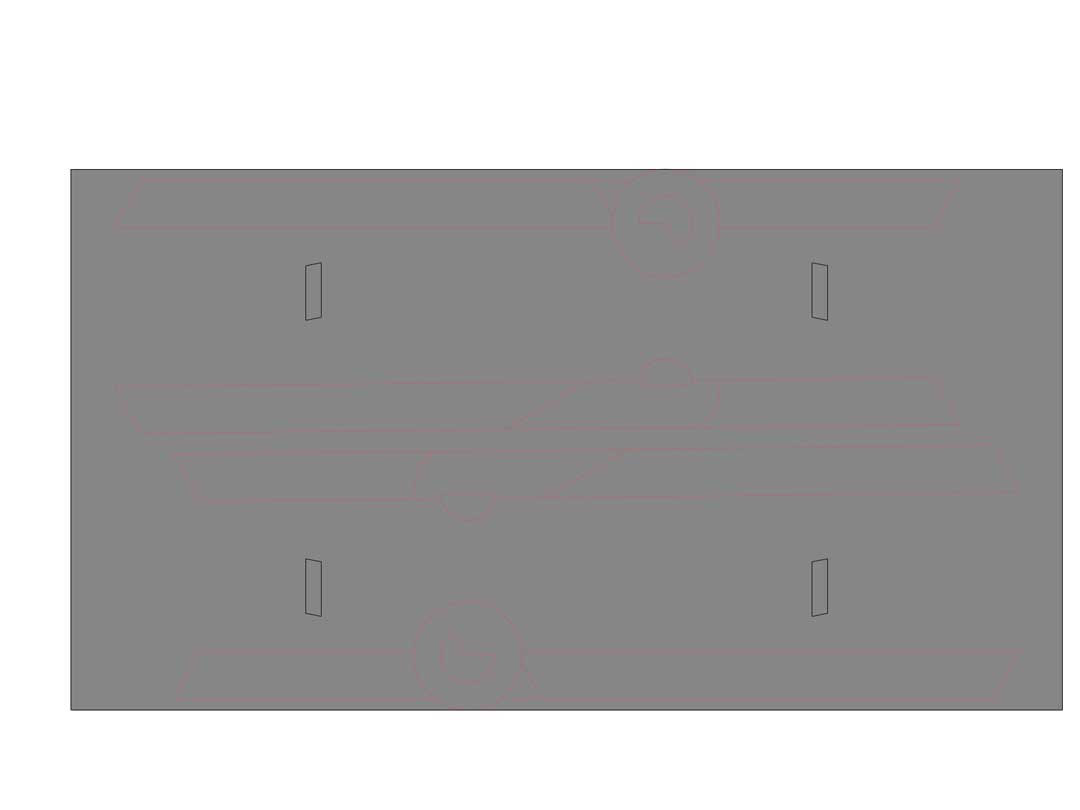
Fig05- Flat pack
Fig06- Table assembled
CAM
I have used Rhino CAM to generate G-code for Raptor X-SL 3200/S20. The strategies start with the placement of the screws on the stock. I used Engraving to go 3mm deep in material. The important point is to put a big jogging distance to prevent any collisions while the stock has not fixed to the board. I separate my design into two part, leg and desktop. In the strategy, I start the cutting from the leg and then went thorough the desktop. The leg design has 2 layers and to fabricate it I had to use 2 different approach. Each layer start with a pocketing on the joinery and it follows with a profiling to clear surrounding of that layer. in the last layer for profiling I had to consider Bridges to keep the pieces attach to the stock to be remove safely. After the legs done the desktop was start with the leg holders. I used pocketing to remove material till depth of 12mm. Then the longest part of file which was the leg placement under the desktop started. after that I used pocketing technique to clear a circle in the middle of the desk to pass wire. I added extra 1mm to make sure it passes trough the material. At the end I did a profiling to take out the desktop from the material.do not forget the bridges! in following you can find some visual of each step that has been explained above.
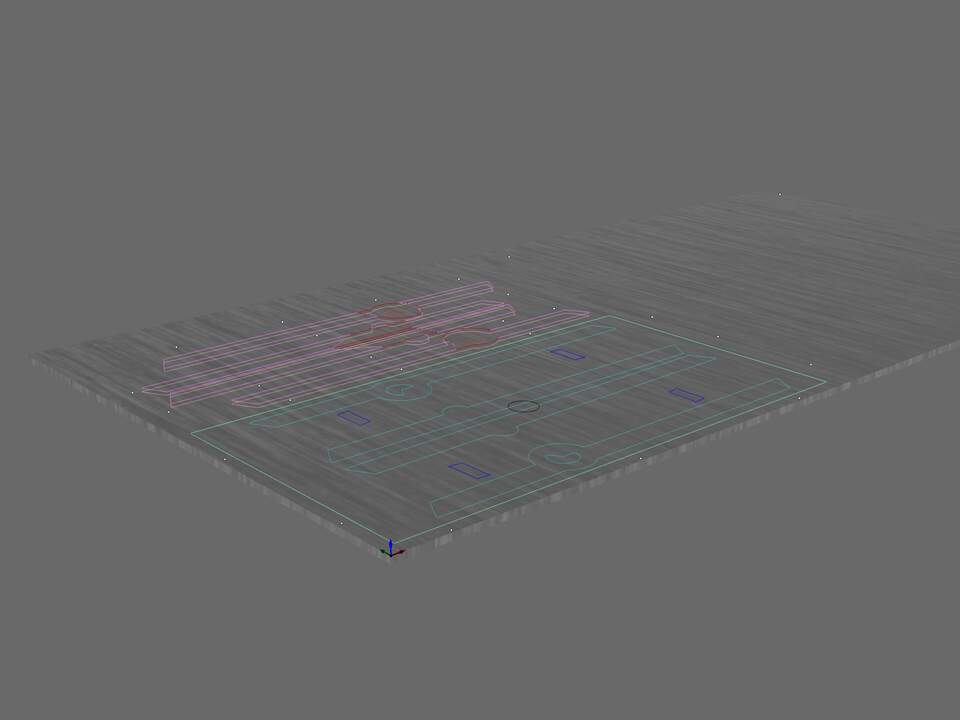
Fig01- define the stock
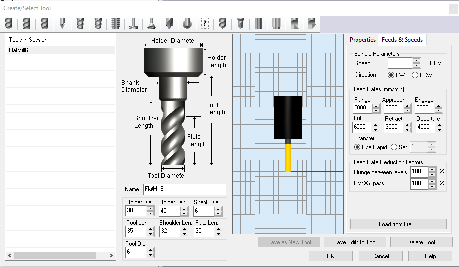
Fig01.1- define the Tool, Feed rate, and spindle speed
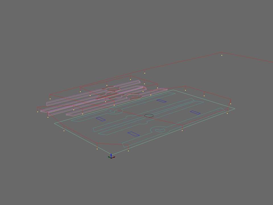
Fig02- The placement of the screws on the material
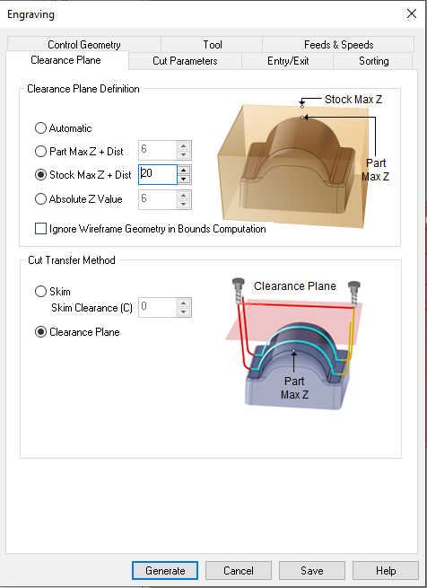
Fig02.1- important tip to make sure the offset from the z plane should be more to avoid spindle touching the stock in case the wood is bended.
Fig02.2- Depth of the cut for screws placements
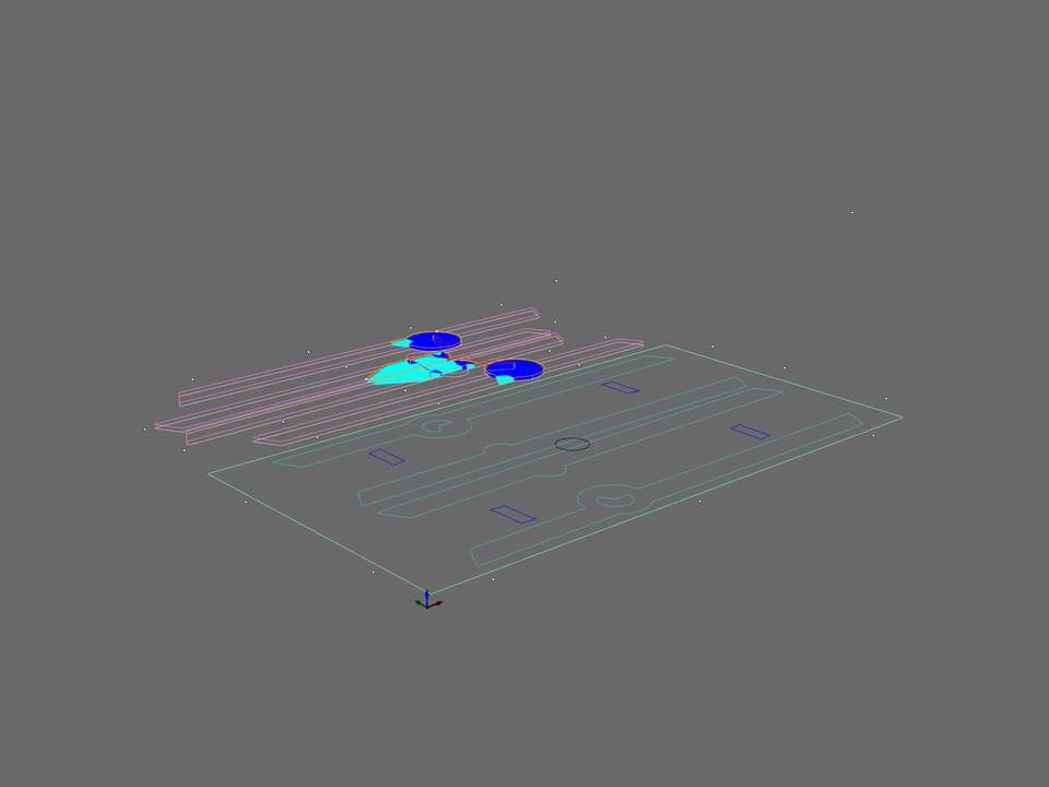
Fig03- First pocketing on the first layer of the legs
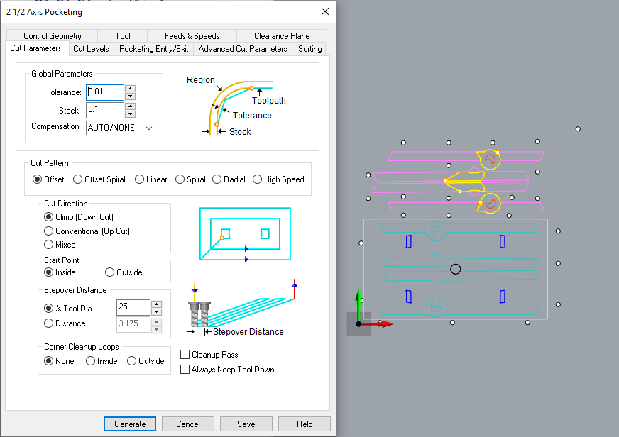
Fig03.1- First pocketing on the first layer of the legs, The cutting parameter the important thing is to choose climb for cut direction
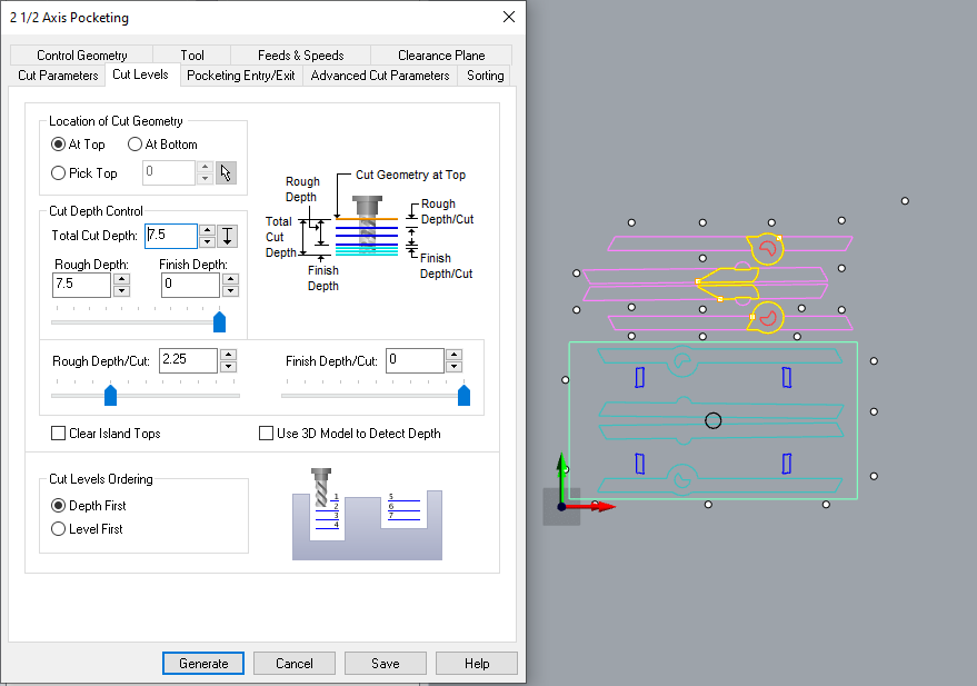
Fig03.2- First pocketing on the first layer of the legs, The cutting level. In this stage I am going 7.5 mm down with 2.25mm steps.
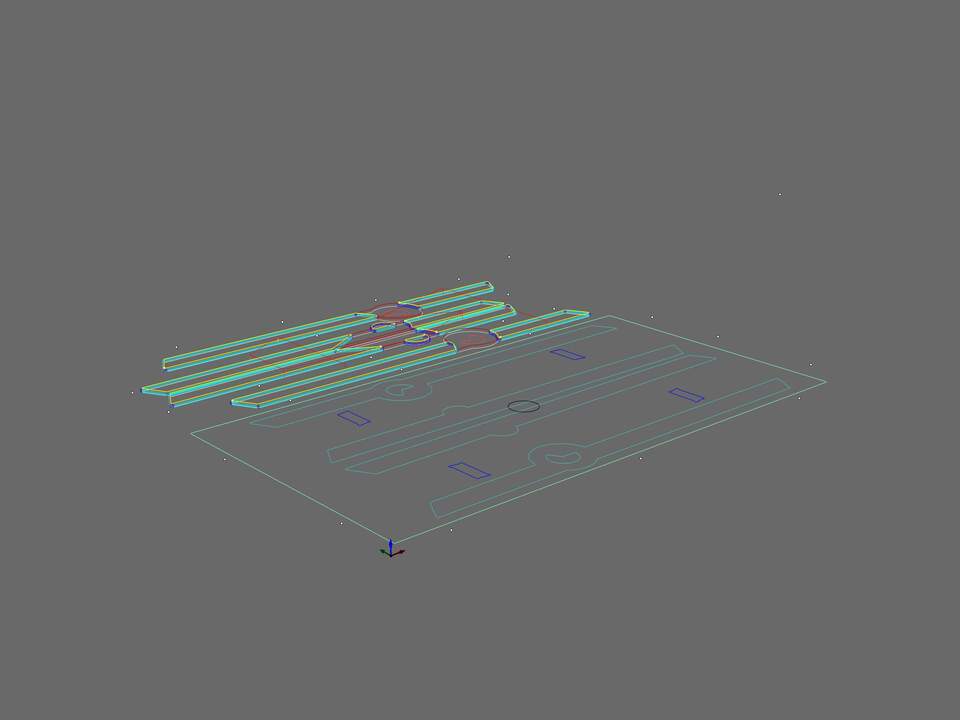
Fig04- First profiling on the first layer of the legs
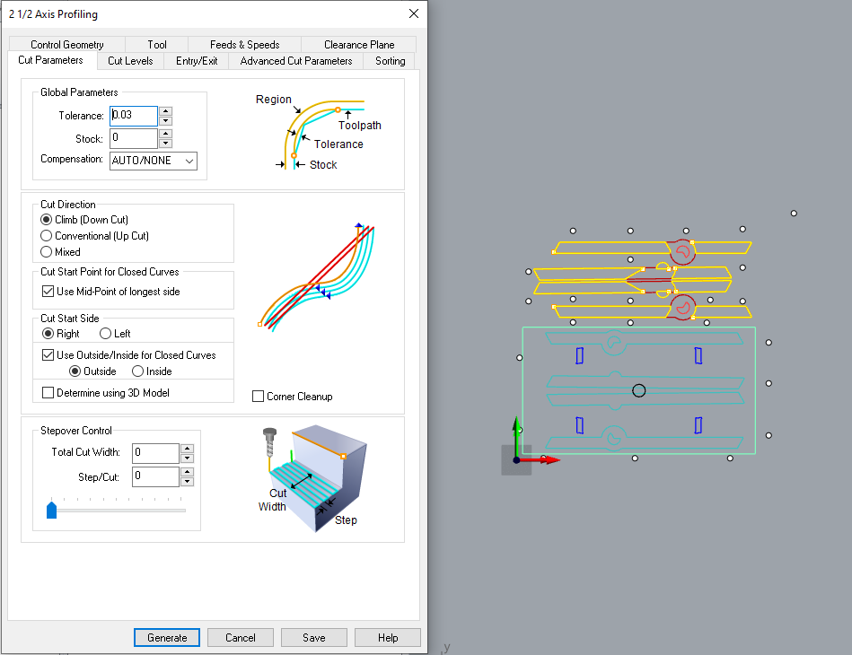
Fig04.1- First profiling on the first layer of the legs, The cutting parameter the important point is to put stock to 0, the direction should be climb, and we need to cut the outside of the pieces.
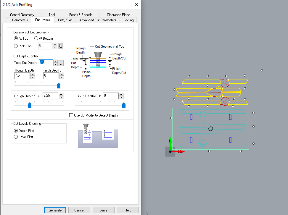
Fig04.2- First profiling on the first layer of the legs, The cutting level is the same as previous pocketing 7.5mm depth with 2.25mm steps.
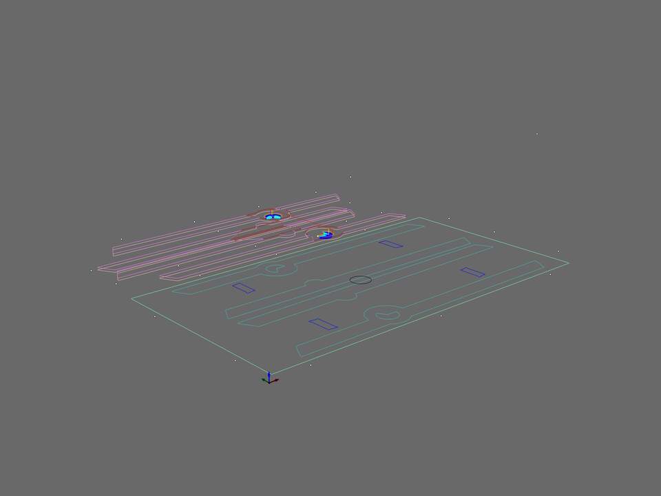
Fig05- Second pocketing on the Second layer of the legs
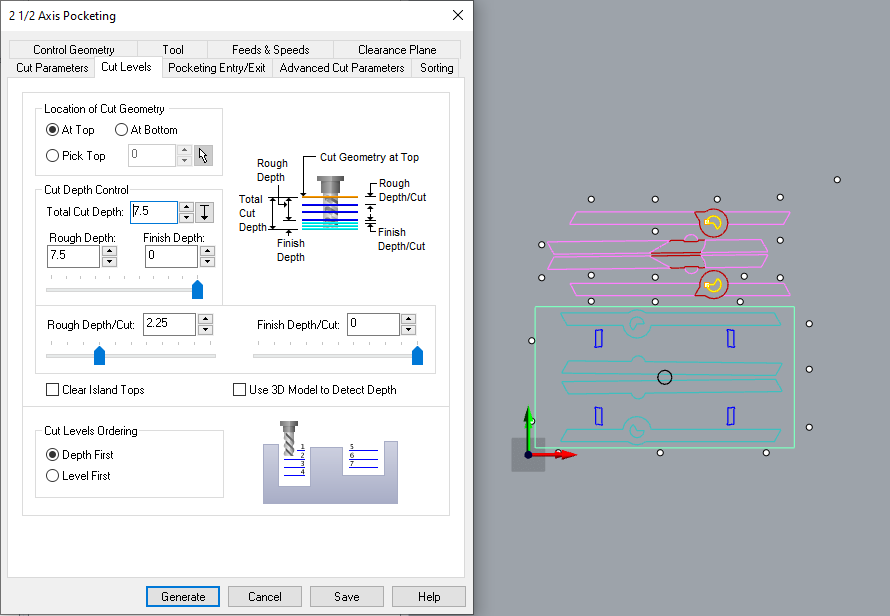
Fig05.1- Second pocketing on the Second layer of the legs, cutting level. keep in mind the defined curve is in -7.5mm already. so basically this process will start from -7.5mm and go thorough the material till 15mm depth.
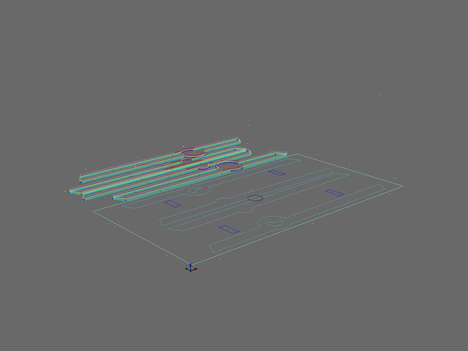
Fig06- Final profiling of the legs
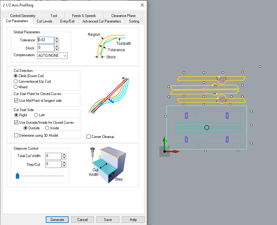
Fig06- Final profiling of the legs cutting parameter. The important thing as I mentioned earlier is to put the stock to 0, select the climb direction, and start the cut from outside.
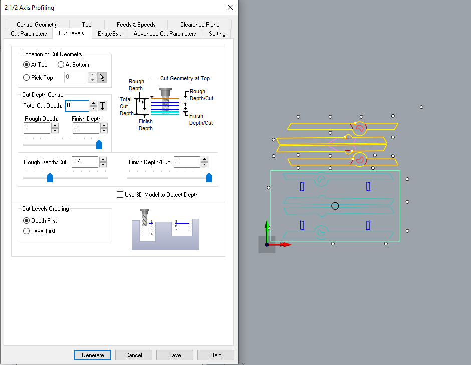
Fig06- Final profiling of the legs cutting level. Same as last profiling, the main curve is located at -7.5mm. So by going down by 8mm, we are cutting from 7.5mm till 15.5. this extera 0.5mm is to make sure we are cutting through the material.
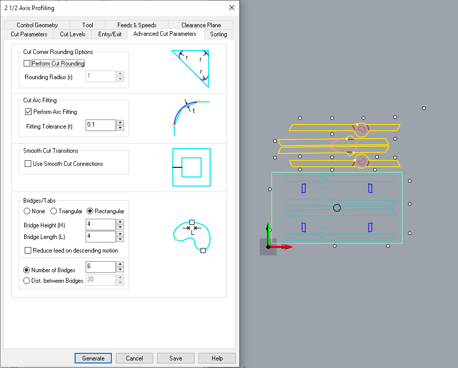
Fig06- Final profiling of the legs bridges. We need to add this bridges to make sure that after cutting, our pieces will not fly around.
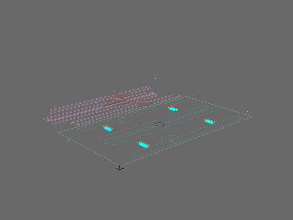
Fig07- The leg holders under the desktop
Fig07.1- The leg holders under the desktop cutting level. the important thin is that I am not going all the way through the material because I want to have a clean top desk. So I am just removing material until 12mm.
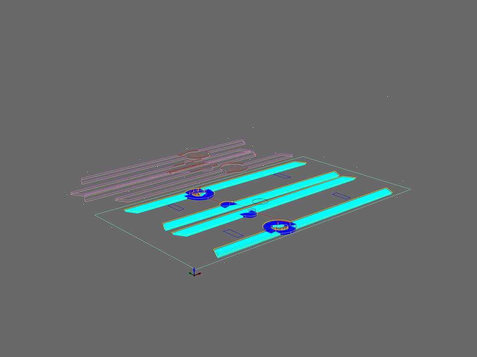
Fig08- The legs placements under the desk that make it possible to pack everything flat.
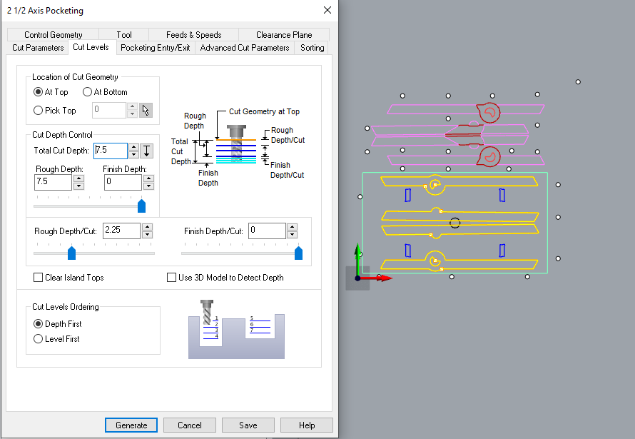
Fig08.1- The legs placements under the desk that make it possible to pack everything flat. The pocketing depth is 7.5mm so half of the legs will be out but it would be good enough to hold them in place.
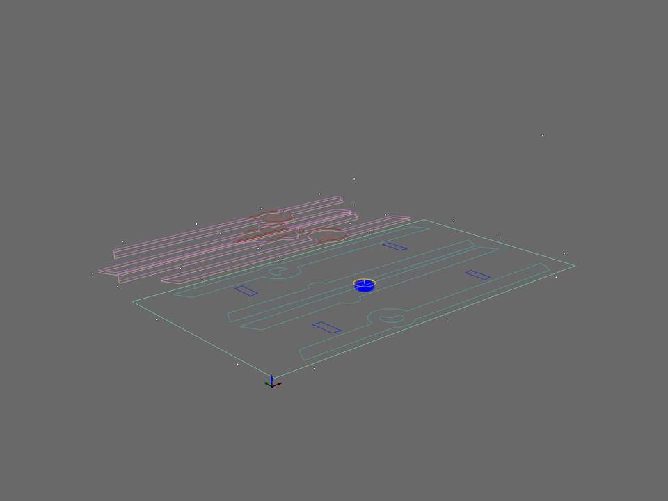
Fig09- The middle hole pocketing for passing wires
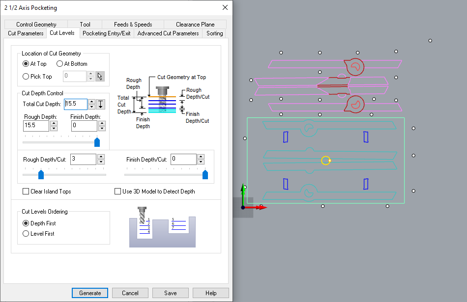
Fig09.1- The middle hole pocketing for passing wires. I used pocketing to make a hole through the material.
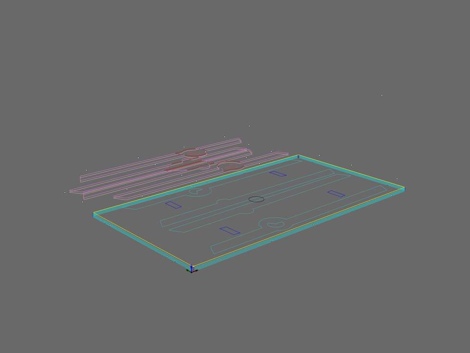
Fig10- The final profiling around the desktop
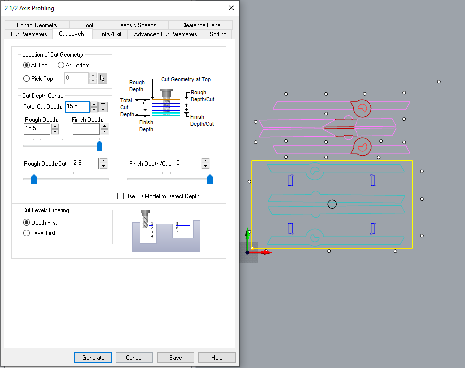
Fig10.1- The final profiling around the desktop cutting level. as you can see I am going until 15.5mm with 2.8mm steps.
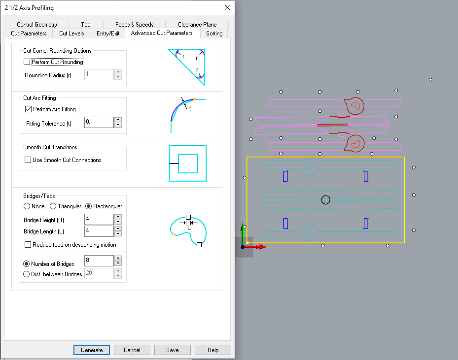
Fig10.2- The final profiling around the desktop bridges setup to make the piece stick to stock after we cut through the material.
Feed rate calculation
To cut this design I am using a 6mm flat with one flute end mill. The speed of the spindle chosen to be around 20000 rpm. Chip load of softwood is in the range of 0.2794-0.3302. with the following formula the feed rate has been calculated
Feed rate = Spindle speed X Flute X chip load
There are also online tools that you can use for this calculation.
At the end I have used - Spindle = 20000 RPM - chip load = 0.3mm - Feed rate = 6000 mm/min
On CNC machine
On the machine first I placed the stock on the board. I used the initial origin of the machine to simplify the setup. The I placed the 6mm flat milling bit inside the collet and fixed it on the spindle. After I made sure that the tool is tight and ready for milling. Then I used a custom program to set the Zero in Z axes on top of the stock. I run the screw file to mark the place of the screws. Then tight the material to the board. Remember after this step we have to run the Z axes Zero again because the material is not flat always and after adding the screws it might change the distance. Then I start sending the leg files to be cut. There was a small problem at the end of leg file. The height of the bridges was not high enough and it broke at the end of the file. After a small clean up I send the file for the desktop which was supper long. In the following you can find so visuals of the process.
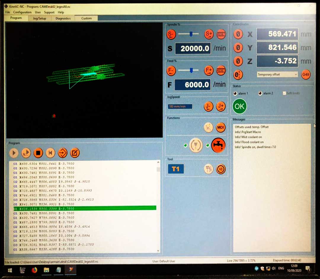
Fig11- The machine interface
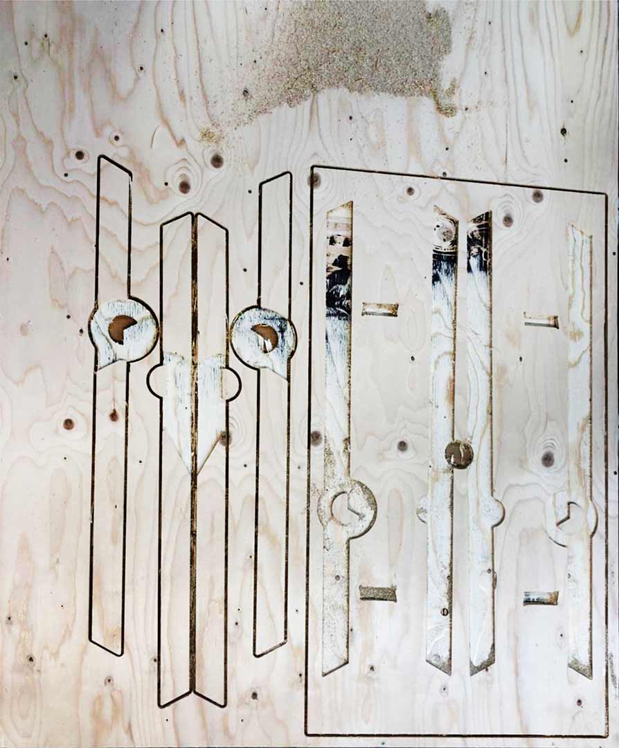
Fig12- The final profiling around the desktop
Link to Video
Big mistake
So while I was using grasshopper to design and generate the fabrication file for this I forgot to consider any tolerances for fitting the joineries. So they did not fit and I need to sand them all a lot to make them fit which was not necessary if I though about it earlier. The big regret is that I did not run a test file to check the joinery before do the entire thing. I put so much faith on my design. :((
If I manage I will re-do the file. meanwhile I will try to fix the current version.
Test the joinery
after the previous experience I took the joinery design and made some file to test before adjusting the whole file. So for this test I offset the outer parts 0.2mm in and inner parts same amount out. For the leg holder join I adjusted to be 0.3mm bigger from each side since the leg are in the angle and need some space for adjusting. you can see the results in the following documents.
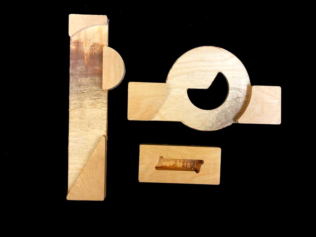
Fig13- The test pieces
Fig14- joinery assembly
Fig15- leg holder assembly
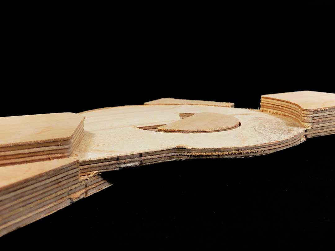
Fig16- Profile of the join
Files
You can download all the files from the following link.