
3.
Computer-Controlled Cutting
Assignments
group assignment
characterize your lasercutter's focus, power, speed, rate, kerf, and joint clearance
individual assignment
cut something on the vinylcutter
design, lasercut, and document a parametric construction kit,
accounting for the lasercutter kerf,
which can be assembled in multiple ways,
and for extra credit include elements that aren't flat
Download the files
Table of contents
-
Trying to parametrise in FreeCAD
-
Switching to Grasshopper
-
Adding the variables
- The Number Slider component
- Starting with the circular piece
- The Circle (Cir) Component
- Creating a rectangle for the notch and copying it around the circle
- Actually there’s a better way to do it… Horizontal Frames (HFrames) component
- The Construct Domain (Dom) component
- Wondering how to cut the notches out of the circle
- The Boundary Surfaces (Boundary) component
- The Surface Split (SrfSplit) component
- The Area component, combined with the Sort List (Sort) component
- The List Item (Item) component
- The Deconstruct Brep (DeBrep) component
- The Curves (Crv) component
-
Connecting peg
-
The living hinge
- Creating the base of the hinge
- Creating the first slit of the living hinge
- Creating the second, shifted Line
- Creating the same line as in in the center
- Copying over the lines x amount of times
- Creating a bounding box of the lines
- The Series Component
- The Move component
- Grafting, what the hell is it?
- Mirroring the slits
- The Explode component
- Adding the circles to the Vertices
- The Point in Curve (InCurve) component
-
Baking
-
Conclusion & how it could be improved
-
Laser cutting
-
Vinyl Cutting with Roland GX340
-
Group assignment
Have you?
Trying to parametrize in FreeCAD
As I had messed around with FreeCAD for the second week assigment I thought I’d keep with it this week and learn even more. Quickly I abandoned it because it kept crashing, and when I had finally created a shape I didn’t know how to get just the curve.
I was told after it can be done by exporting to DXF format.
I actually have a FreeCAD file of my press kit, but FreeCAD crashes when I try to open it. Still, you can download it below.
Download FreeCAD projectI decided to go with Grasshopper because I wanted to be able to Bake the curves straight into Rhino with different parameters for testing. I’ve also wanted to learn Grasshopper for a while so this assignment forced me to.
Switching to Grasshopper
As the assignment is to work with parametric design I wrote down what variables we were going to work with.
In Grasshopper I put all my variables on the far left so I could easily tweak them and try them.
-
Global variables
- Thickness of the material I’d be cutting (which controls the width of the notches)
- Depth of the notches
-
For the circular pieces
- Radius
- Number of notches
-
For the living hinge
- The total width and height of the piece
- The distance between the hinges
- The length of the hinges cut
- The number of hinges (minimum of 5 in total)
-
Connecting pegs
- Width and height
Ok, let’s type all these variables into sliders, roughly guessing what we need.
Adding the variables
The Number Slider component
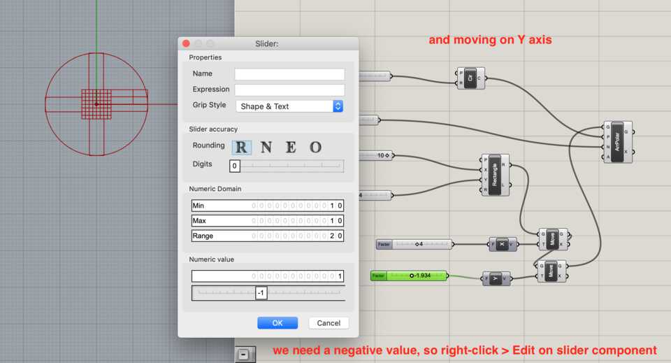
Simple double click with a number creates a slider by entering a number. If you enter 2, it creates a range from 0 to 10. If you type in 0.45 it creates a slider from 0 to 1 with 2 digits after the decimal. In many cases I right-clicked on the Slider component and clicked Edit.
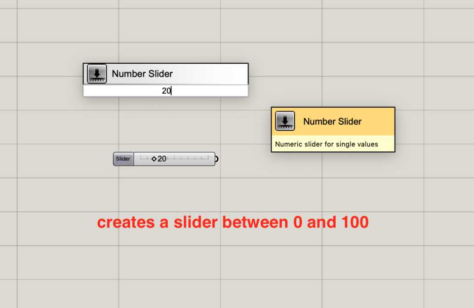
That allows you to change the settings of the slider, to add or remove digits after the comma, change the minimum and maximum value of the range.
Starting with the circular piece
The Circle (Cir) Component
Double-click and type in Circle, make sure to choose the one with the orange background, as that is an actual circle. The black icons are holders for collections of objects.
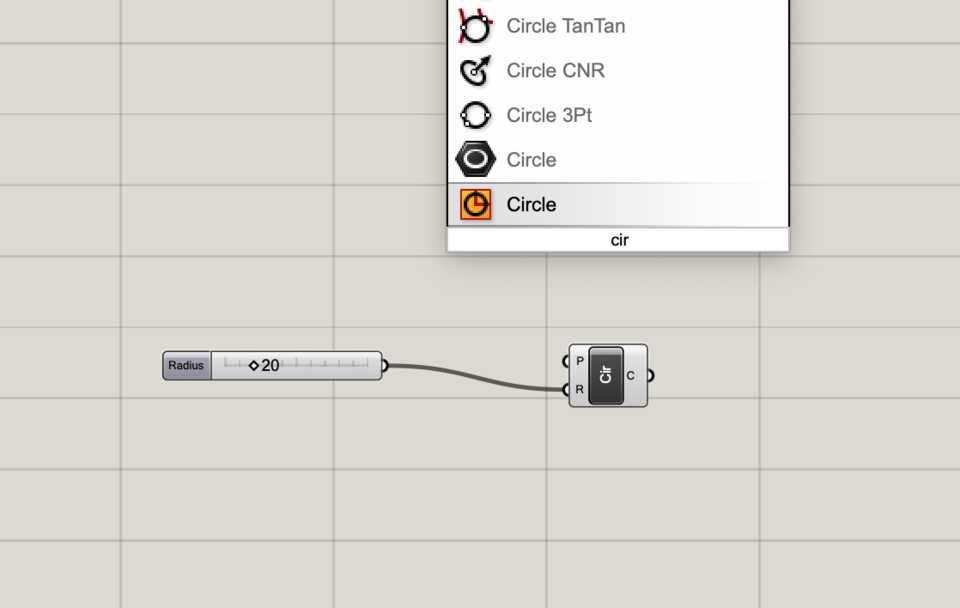
Drag the radius variable to the Radius (R) input.
Creating a rectangle for the notch and copying it around the circle
I started creating a Rectangle for the notch (again, make sure to use the component with the orange background), setting an X and a Y to determine its size.
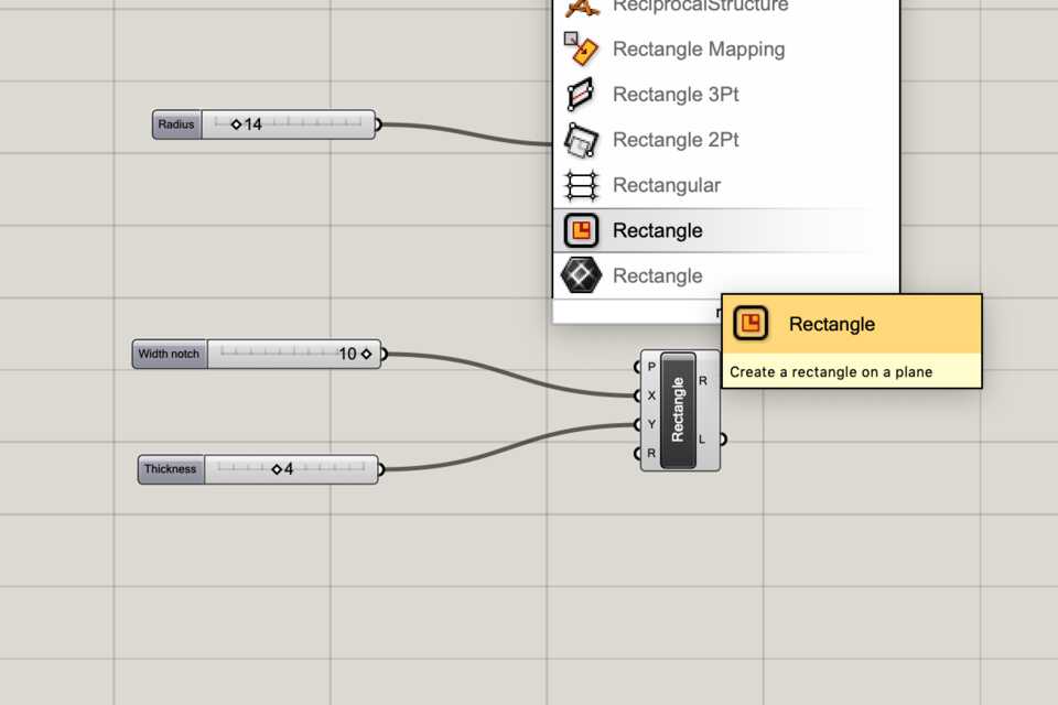
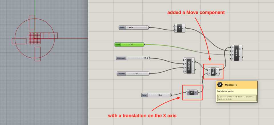
Then moving creating a Polar Array (ArrPolar).
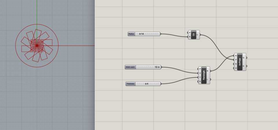
Then trying to place it by using a Move component on the X axis.
And the same on the Y axis.
Actually there’s a better way to do it… Horizontal Frames (HFrames) component
I asked Arman to help and he pointed me to a Horizontal Frames (HFrames) rather than using Polar Array, which when being plugged in with the Circle creates a local plane to work from, with its own origin. There you can build the Rectangle as you wish. Let’s try it.
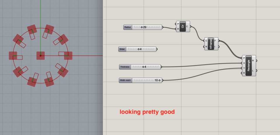
The HFrames takes in a Curve (C) input, to which we plug in the Circle, and a Count (N) input, to which I plug in the # of notches variable.
I was giving the rectangle a width and height, and then I was trying to move it up or down to align with the center of the circle, but it didn’t work.
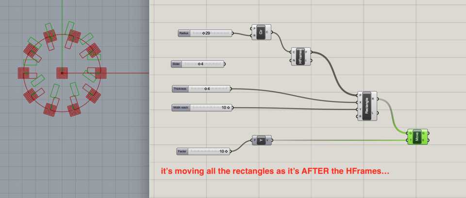
Once again Arman came to the rescue and explained how with the Domain component you can set two values as the minimum and maximum value for the size of the Rectangle, in relation to the HFrame.
The Construct Domain (Dom) component
Having a variable for the width and height of the notch, I had to do a Division by 2, and plug in that value to the Maximum (B) input of the Domain.
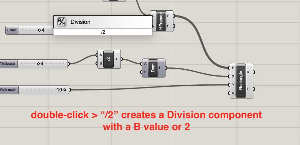
I now need to feed it the Minimum value, which is the same value but its negative equivalent. How to do that? Plug the value of the Division above to a Negative component, and then plug its output to the Minimum (A) input of the Domain.
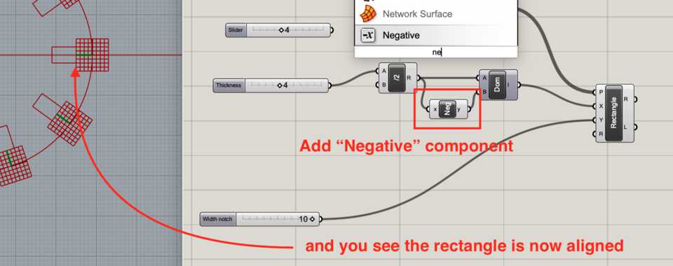
The result of Domain is then plugged into the X of the Rectangle component.
Note //this technique is used multiple times in the project, so I won’t explain it everytime, I’ll just mention “the Domain technique”.
As for the Y value of the Rectangle, it simply is the depth of the notch (just realised I miss named the sliders).
Wondering how to cut the notches out of the circle
Ok… we have the circle, and rectangles that go around it. Now I want to cut out those rectangles out of the circle.
How to do that… *Arman the Grasshopper wizard*
- “Armaaaaaaaaan?! How do you do… things?”
- “Oh, yeah, it’s simple, add a boundary to the circle then just do a surface split with the rectangles. Finally sort the faces by area with the sort list, list the item and get the last index, apply a simple brep deconstruction to them, grab the edges and that’s it.”
- “...”
- “What?”
He explained to me step-by-step and that actually helped me a lot understanding Grasshopper in general.
With Grasshopper you have to see everything deconstructed to the simplest… it’s not a rectangle, it’s 8 vertices, 8 edges and 8 surfaces. If you want to manipulate them you have to filter them with different modules.
Back to trimming the circle with the rectangle, let’s explain it step-by-step.
The Boundary Surfaces (Boundary) component
Double-click and create a Boundary Surfaces component which creates a surface out of Edges, in this case the Edge of the Circle. That’ll allow us to have something to subtract from later, in this case the rectangles/notches.
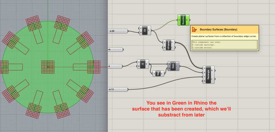
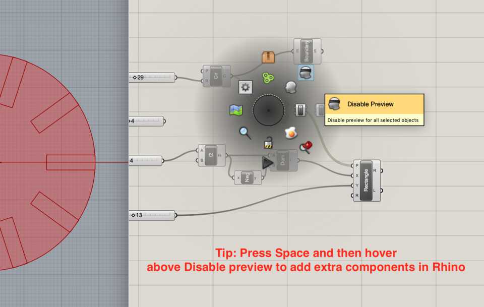
Tip: Press Space to show a quick menu, and from there you can Enable and Disable Preview to keep the essentials in Rhino.
The Surface Split (SrfSplit) component
Next you have to split the newly created surface with Surface Split, and Grasshopper describes it nicely with “Split a surface with a bunch of curves”.
It takes in two inputs: S, the Surface to split, in our case the Boundary Box, and C, a list of Curves to use to do the splitting. The output of this component is F, a list of Fragments, in other words a bunch of surfaces.
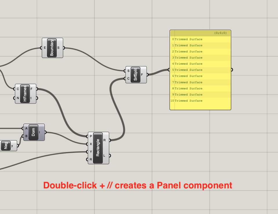
Note //You can check the result of any component with a Panel component by doing Double-click + //.
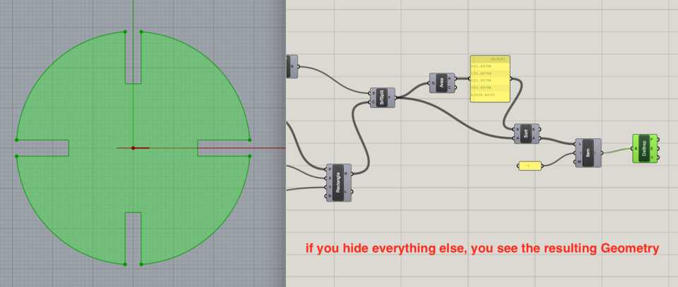
That means that now the Circle is broken down to multiple surfaces of different areas. Visually you can tell it’s x amount of surfaces of equal area (created by the rectangles), then one big surface which is the rest of the circle. We want to get that big surface and extract its edges into one curve.
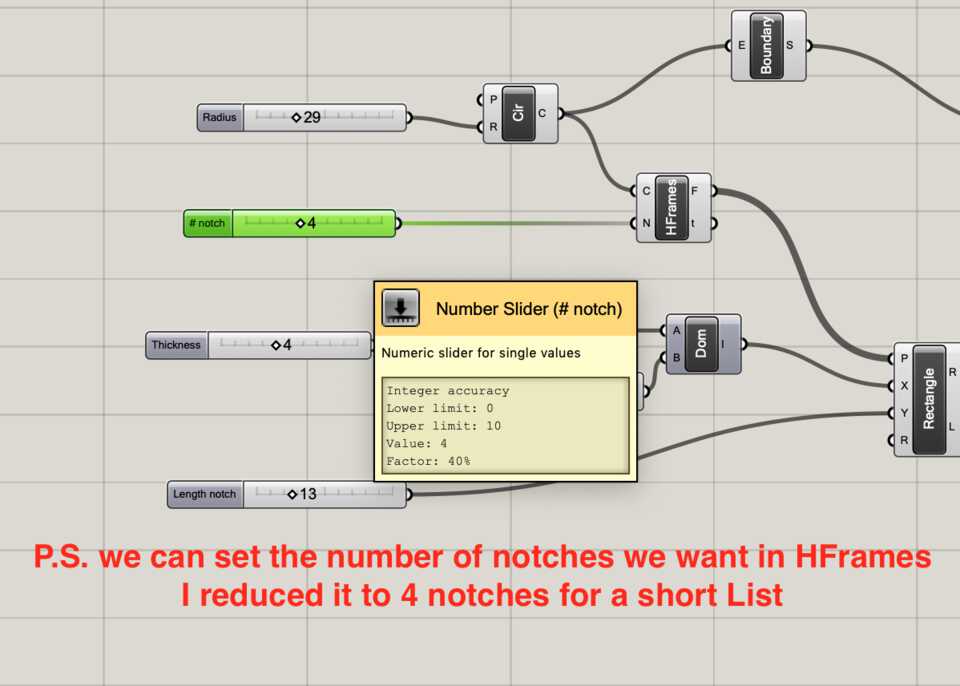
That calls for a few steps.
The Area component, combined with the Sort List (Sort) component
As we said, Surface Split outputs multiple Fragments, aka Surfaces. We want to get their Areas and Sort them into a list. We only want to extract the surface with the biggest area, so it’ll be either at the start or at the end of the list.
Let’s add the Areas component and plug in the Fragments from the previous step to get a list of the areas of the surfaces.
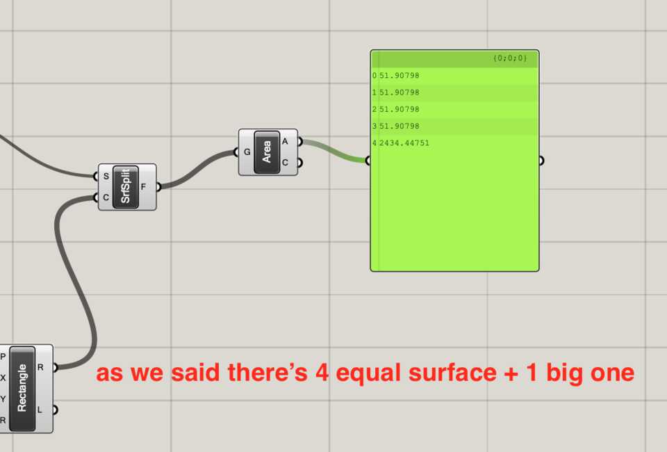
That list can then be used as a Key for the Sort List component, which puts them in order from smallest area to biggest. But first you also need to input what you want to sort in the Values A (A) input, so let’s drag the Fragments from the SrfSplit component.
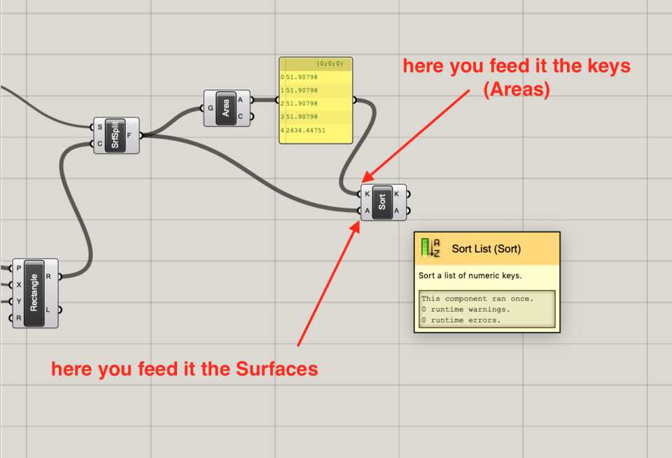
The List Item (Item) component
As all the areas from the rectangle are equal and obviously smaller than the rest of the circle, the surface of the circle is at the end of the list.
To pick that last Item of the list add the List Item component and for the Index (i) input, input -1.
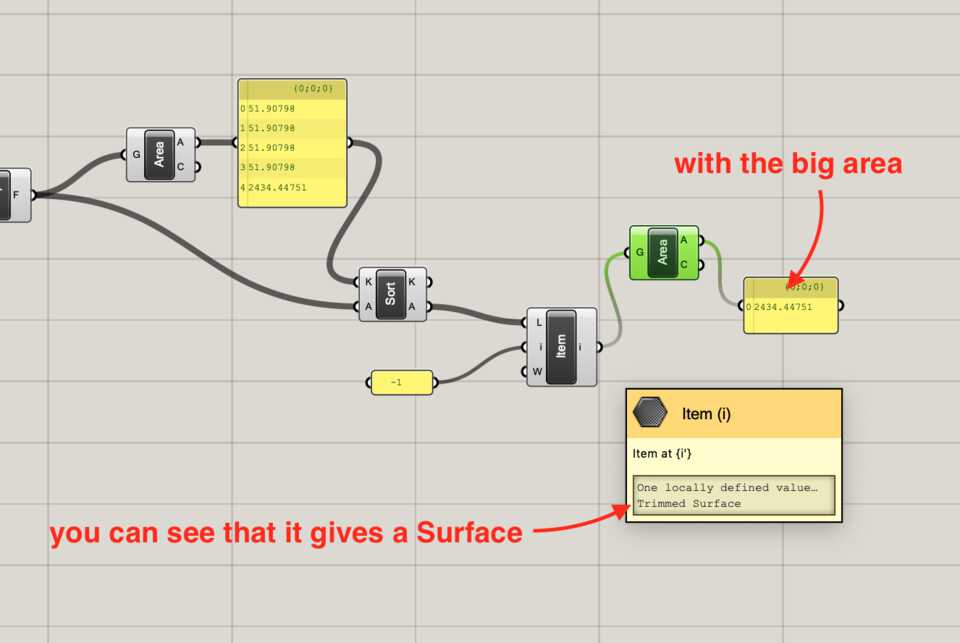
Note //you can use the Panel component to input specific values. Double-click // -1.
The ouput of the of the List Item component is the biggest surface. We now want to access its Edges.
The Deconstruct Brep (DeBrep) component
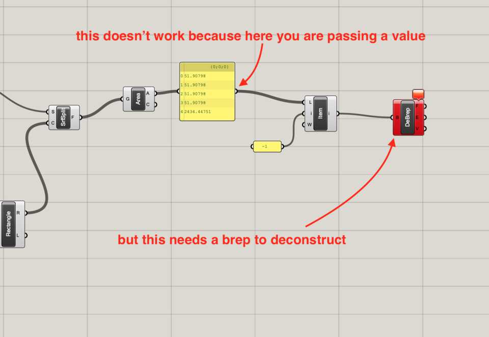
Input the result of the previous step to the Deconstruct BRep component, which outputs F, E & V, or Faces, Edges and Vertices respectively. In this case we want to take all its Edges.
P.S. Before using the Sort List, I had tried to feed in the value of the Area component to the DeBrep, which didn’t work as it expects a geometry, not a number.
The Curves (Crv) component
Finally add a Curve component, input the Edges from the previous step and here you are! A continuous curve tracing the outline of the circle with notches in it.
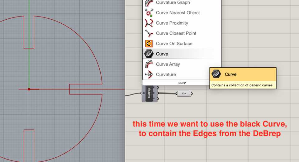
Now, onto the connecting peg.
Connecting peg
After the previous step, the connecting peg is pretty straight forward.
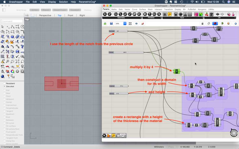
Create a rectangle and define its width and height.
Create another rectangle that has a width defined by the notch depth variable and a height defined by the thickness of the material.
Using the Domain technique align to the right (or left) of the main rectangle, and then mirror it to the YZ plane.
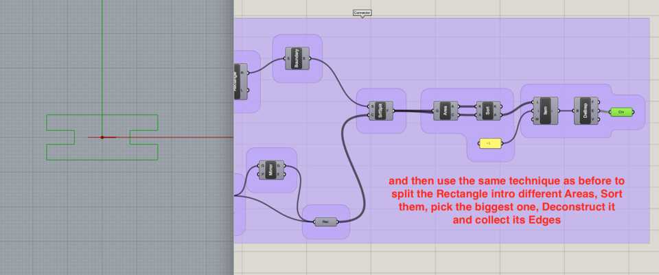
Using the same technique as above with SrfSplit, Area, Sort Items, List Item, etc. pick the biggest surface, Deconstruct it, grab the edges, and here you are, a curve to cut.
The living hinge
Now to the challenging part, creating the living hinge.
My plan for creating the living hinge was to have a line in the middle, like you see in the designs, then create the interchanging pattern on one side and then mirror it to the other side… then somehow copy that pattern over… before doing the mirroring… ok let’s see about that when we get there.
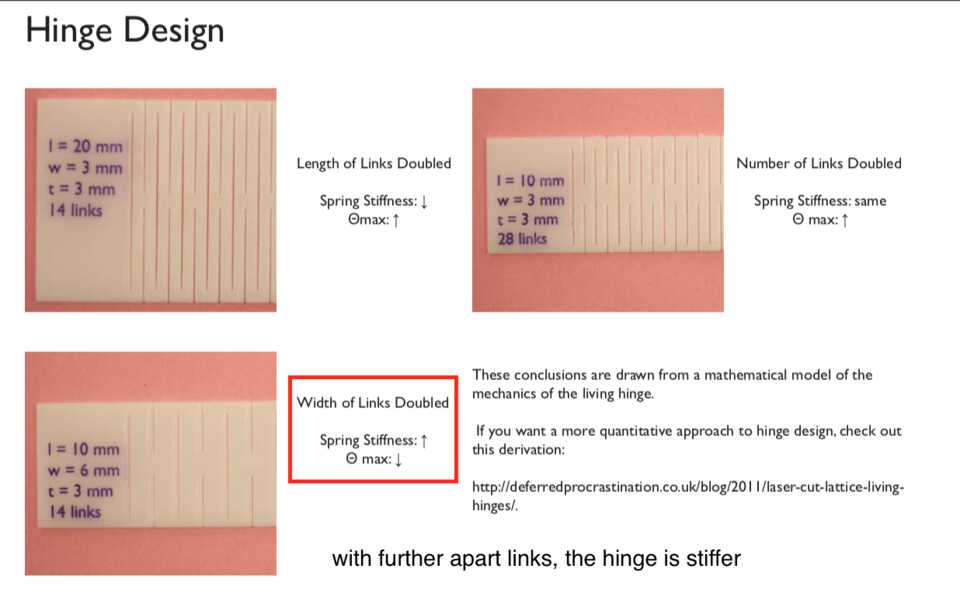
P.S. the science behind living hinges
Creating the base of the hinge
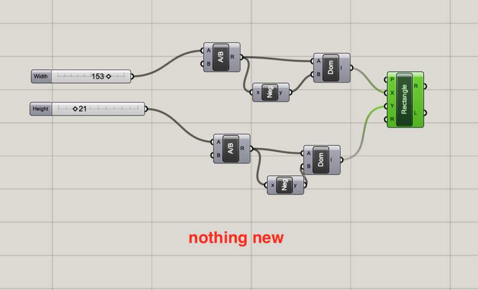
To start, as always, create the base of the hinge, which is just a rectangle and set its width and height with the variables we defined using the Domain technique.
Creating the first slit of the living hinge
I’m going for the basic interchanging pattern, so I need to create points that I will then join into a line. This step is all about placing the points in specific coordinates, relative to the height of the living hinge.
I created a variable called Slit Length (how long the slits are) which I then subtract from the Height variable after dividing it by 2. That positions the point in the Y axis.
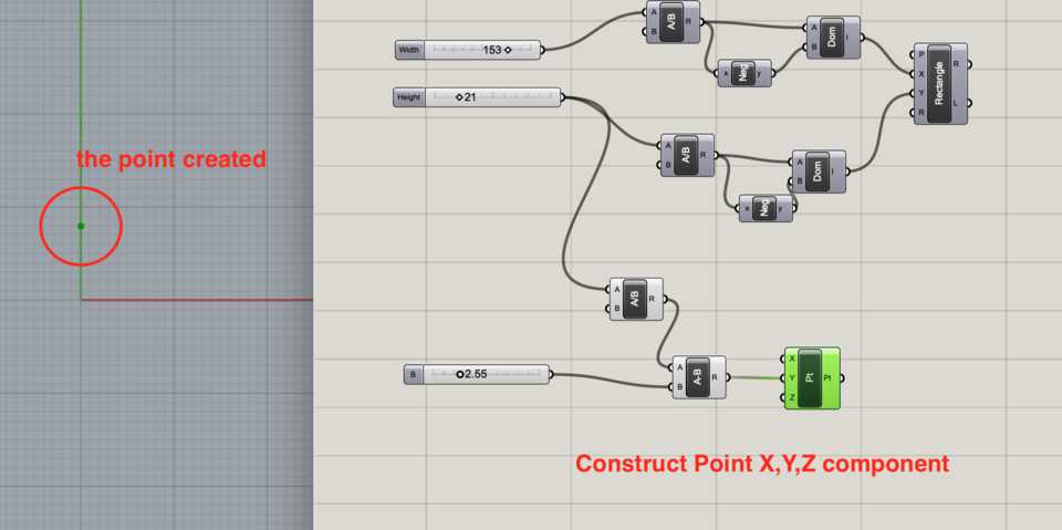
I can then Mirror it to the XZ plane.
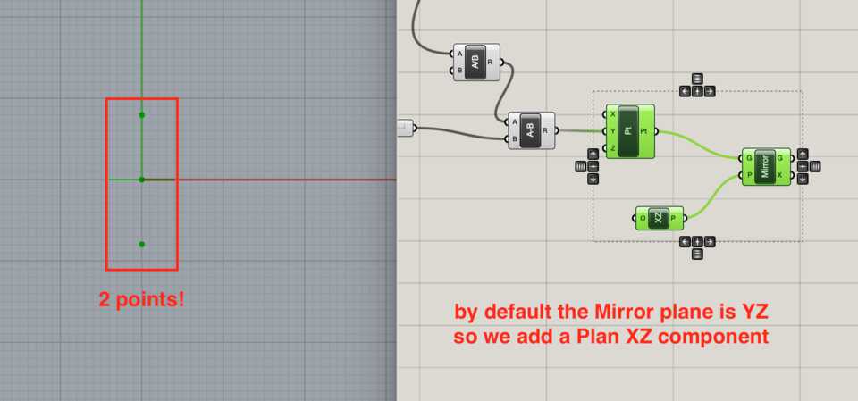
And connect those points into a Line (Ln) component.
Creating the second, shifted Line
The interlocking pattern is built by adding a point with a Y value of Hinge Height divided by 2, which puts it on the edge of the hinge.
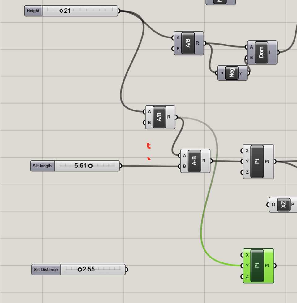
Then another point with a Y value of the Hinge Height divided by 2, minus the Slit length divided by 2.
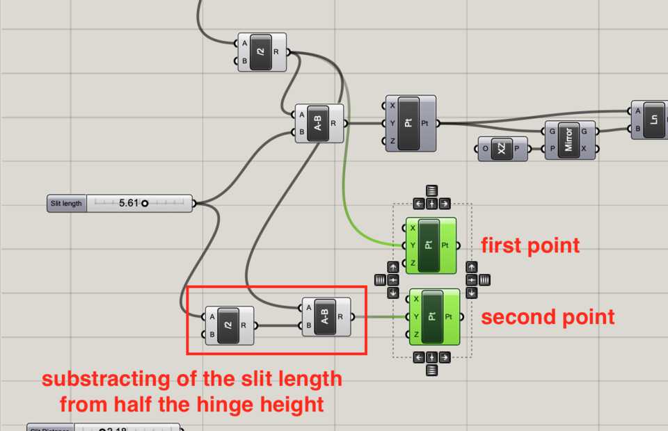
That gives a line that goes from the top of the hinge down. Both of them has is moved on the X axis by the Slit Distance.
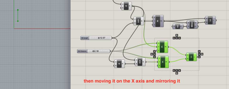
Again, mirror it on XZ plane and plug these two points into a line.
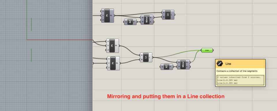
Creating the same line as in in the center
Create the same line as the one in the middle, but change it’s X value to twice the Slit Distance.
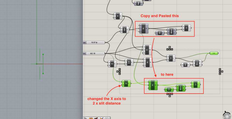
I added the three lines created into a Line Collection module as I’m planning to use that collection to copy it over.
Copying over the lines x amount of times
Now, it’s time to copy the 3 previous lines we created. I tried by doing Duplicate Data (which has a funny icon).
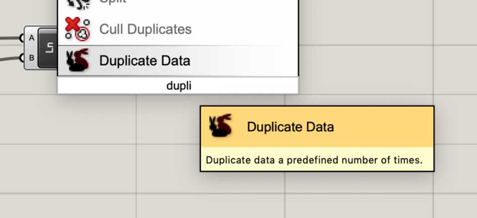
I had to ask the good ol’ Arman to help with it again, because I was getting lost…
- “Eaaaassyyy. Basically you want to know the width of the living hinge slits, right? So then you can move them x times by that width. So, you create a bounding box of all the lines, then deconstruct it so you can get the edges… yeah? Then measure them with Length, do that thing we did before by sorting it then picking the shortest value, which will be the distance between the two slits. Get that distance, multiply by two (because otherwise they are just touching each other rather than being separated). Then you connect to Series module which allows you to repeat a component a certain amount of times… that component take in the number of times you want to repeat it, and as well the amount, which is the 2*width we just calculated”... ok so you want to move it on the X axis, so add an Unit X, plug that into the Move component… wait it’s being weird… Ah yeah, Graft the input… here you are! That’s it. Easy right?”
- “Uuuuuh, yes, I’ll go through it and understand later”.
Later, to myself …
- “Why are we trying to calculate the width of the two slits when I’m giving them explicitly through the width variable…”

Still, it was interesting to learn about these new components, so here’s the long way to get the same result.
Creating a bounding box of the lines
This allows us to work with the pair of hinges’ slits (the 3 lines) as one object, therefore allowing us to get it’s Edges, Surfaces and Vertices .
The aim here is to get the width between these slits (which were set in the width variable). To get the width you Deconstruct (BRep) the Bounding Box that we created and use it’s Edges output.
We use the Length component to get the length of the Edges, and then use that to sort them to get the 2 smallest Edges first (the width) and then the 2 biggest Edges second (the height of the hinge piece).
Add a List Item component to pick the first result, and multiply that result by 2 so that when we move it, we move it the same distance away on the right, so it isn’t stuck to itself.
Now we come to the part where we can’t get around it. The good part. Moving it, multiple times.
The Series Component
-
It takes a few inputs:
- S for Start, the first value to start from, by default 0
- N for Step, which is the amount we want to do whichever operation after, that’s where we plug in the result from the previous step, so 2 x width of hinge
- C for Count, which is how many hinges we want to add (essential!)
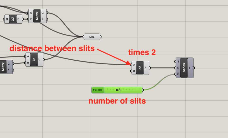
The series component tells the next components to do what they do, C amount of times, with specific values (N).
In our case it tells the Unit X component the value to be multiplied with, which then tells the Move component the direction and amount.
The Move component
The Move component has for input the Geometry (G) and the Motion (T). The Geometry is the collection of lines from earlier (the hinges’ slits to copy) and the Motion is Unit X component from the previous step.
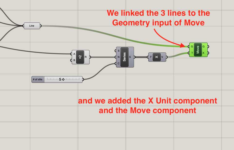
Note //these values are lists, and therefore there are 5 items of an Unit X which is given from the Series component
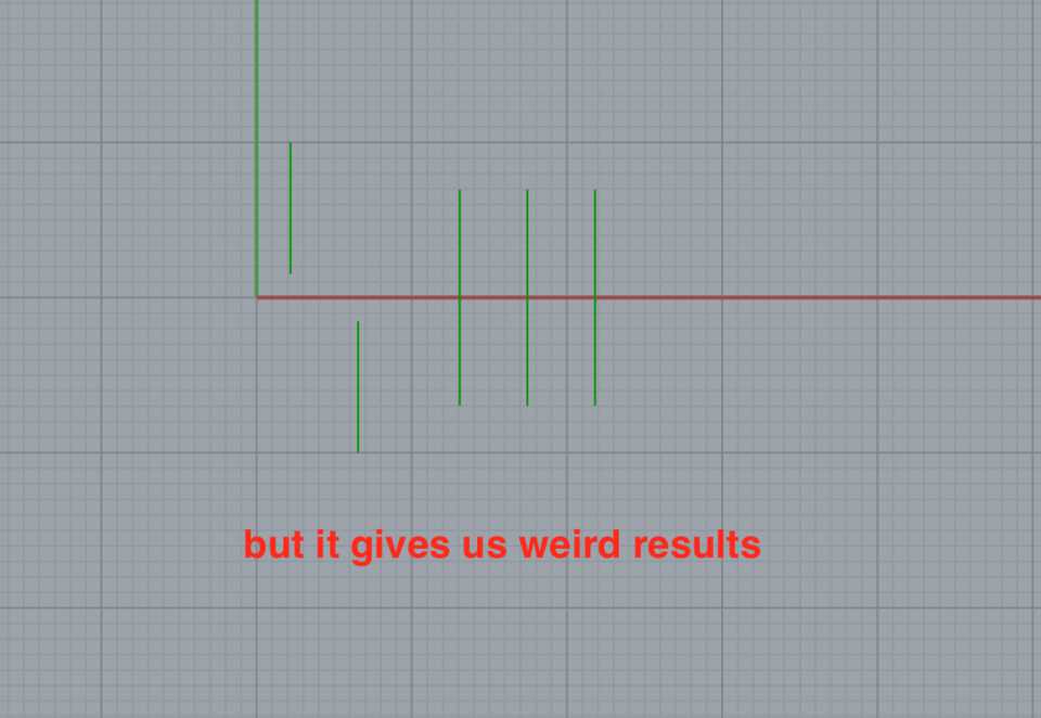
We have some weird results though...
Grafting, what the hell is it?
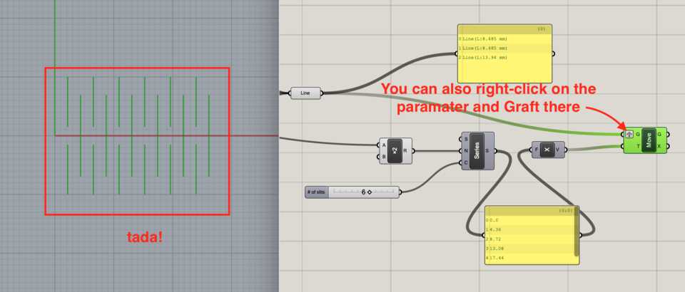
Arman told me I had to Graft the Geometry parameter for it to work… and it did! but I don’t understand why.
I remember Edu showing us in our first Grasshopper class that if you do an operation on a list with another list, for example have a list of [1, 2, 3, 4] and you multiply it by another list, for example [1, 2, 5, 7, 2], then you’d run into a “problem”.
Each item of both lists multiply with it’s “twin-item” in the other list, but what happens when one list is bigger than the other? The operations continue, but the last item of the shorter list is used. See table below.
| List 1 | List 2 | Resulting List |
| 1 | 3 | 3 |
| 2 | 1 | 2 |
| 2 | 3 | 6 |
| 4 | 8 |
You notice that the Resulting List has the multiplication of the two numbers on the left. You also notice that despite having no 4th value in the first list, there’s a value in the last row.
You can see it in Grasshopper… by creating two lists of integers, and displaying them in the Panel components.
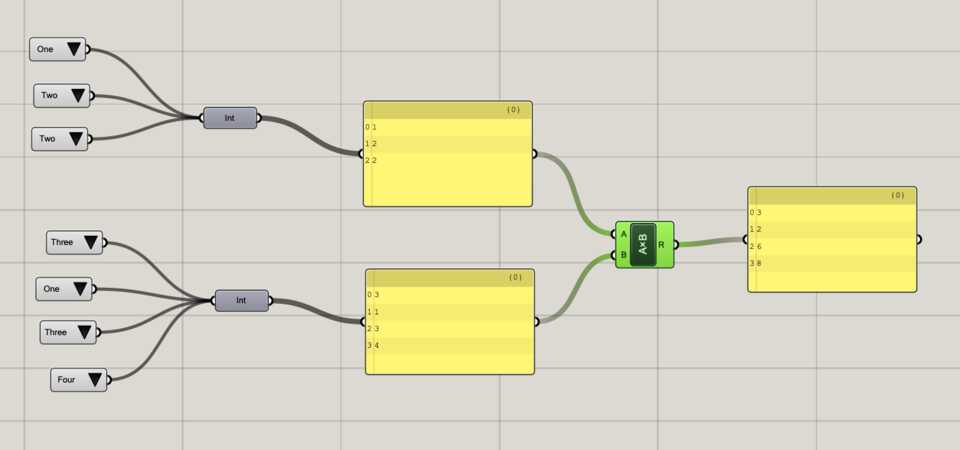
… but if you Graft the first list before sending it to the multiplication component, you can see that the multiplication outputs 3 lists.
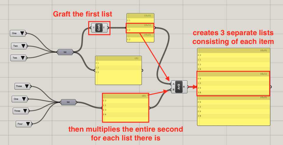
That’s because Grafting basically creates a list with each item of the list you are grafting, so [1, 2, 2] becomes [1] [2] [2].
I think that is what is happening to our lines. The last line gets repeated multiple times because it’s the last item in the Line collection.
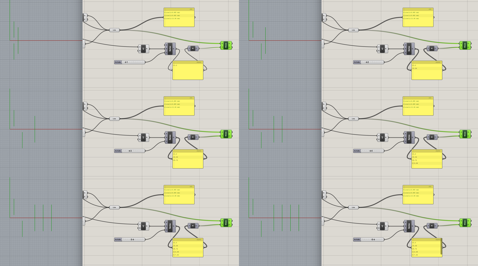
If we Graft the Line collection, then each line is passed independently, and the Move component is applied X amount of times to each line.
Mirroring the slits
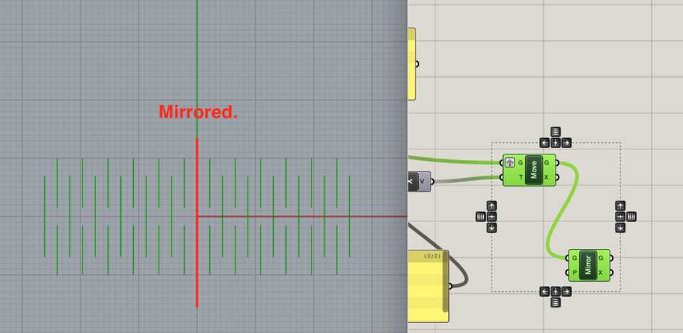
Nice, the hard part is done. We’ve managed to copy the elements on the right, using a slider to decide how many times, and then being able to adjust the width between the hinges. Now, we can use the Mirror component to copy that to the other side of the design.
Add the Mirror component, by default the Plane it uses is the YZ plane, which is what we want, so leave it like that.
I read online that it’s good to add circles at the end of the slits because it relieves stress and avoids breaking. With my understanding of Grasshopper so far I had an idea of how to do it.
The Explode component
First, you have to get all the lines of the hinges into a Curve collection, and then collect all the vertices to use as the center of some circle objects. By browsing the Grasshopper bar I found an icon with “Explode” on it. It seems like it could help, let’s drag it on.
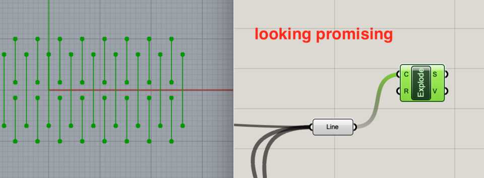
The Explode component takes in Curves and gives out Segments and Vertices.
Adding the circles to the Vertices
The Circle component asks for Plane and Radius as inputs, but I need to decide the center of it. I visited the Curve tab and looked in the Primitive dropdown… There’s something called a Circle CNR component, which when hovering says “Create a circle defined by center, normal and radius.”. That’s perfect, let’s drag it on.

I drag the vertices from the Explode output to the Center input, and tada!, circles appear. I added a slider to decide it’s Radius.
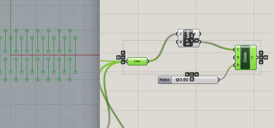
One thing though… there are circles on the edge of the hinge, which I don’t really want to. I need to be able to say something like “Only do the ones that are not on the edge, or that are in the rectangle”. So, WWGD? (What would Grasshopper do?). Inside the rectangle means inside the edge of it, and the edges are curves, so, maybe say if the point is inside a curve? Let’s double-click and see if there’s something that comes up…

Ha! Yes, that was easier than I thought.
The Point in Curve (InCurve) component
It takes two inputs, the Points you want to check are in the curve, and of course, the Curve itself.
Let’s drag the Rectangle we created earlier as the base of the hinge to the Curve parameter, and of course the Vertices from the Explode component to the Points parameter.
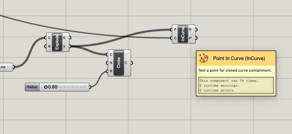
The outputs of the Point in Curve component are Relationship (R), which gives 0 if a point is outside, 1 if the point is on the curve or 2 if the point is inside the curve, and P’ which are the “points projected on the region plane”... It’s the same amount as the ones intaken, so I guess it just outputs them all out.
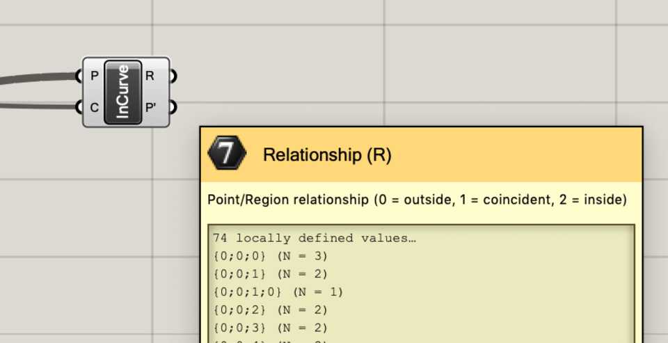
We want to check that the point is inside the curve, not coincident or out, so let’s check with the list of Relationship that it outputs (you can see some 2s and 1s).
I struggled with the step above but found the solution while Googling, the answer is available here.
Basically you add a Equality (Equals) component, input the Relationship output from InCurve into A, and then input 2 into the input B. It outputs True or False.
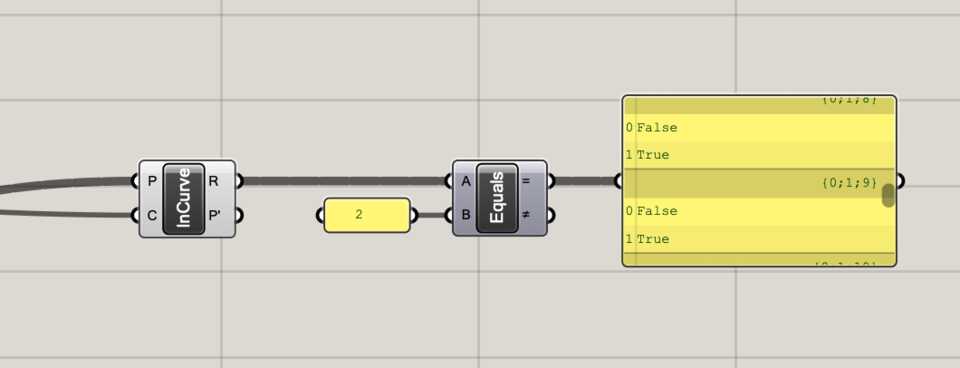
Then add a Dispatch component which separates its input, a List (L), into two different lists depending on the condition. The condition is given in the Dispatch pattern (P) input. If true, it comes out of A. Let’s plug the = output of Equality to the P input of Dispatch, and finally the A output of Dispatch to the Center (C) input of Circle…
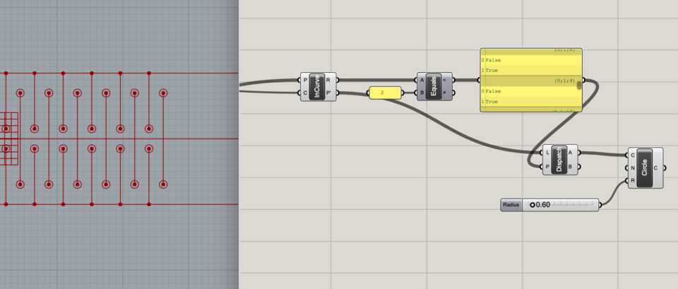
Boooom! It works! Making Grasshopper work on my own, oh yeah.
That’s it! Just need to compile all the curves/lines I created in this project into one big Curve collection which I can now Bake into Rhino. Beautiful. It’s been emotional Grasshopper.
Baking
I love baking. It’s simple and easy, you can either right-click > Bake, or press the spacebar above the component, and then click on the egg icon. Tada!
Conclusion & how it could be improved
I really enjoyed doing this. Once you get how Grasshopper works, you can quite quickly get the hang of it and design stuff.
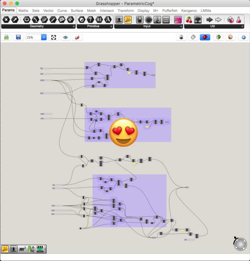
Here are is my Grasshopper file for download.
Download Grasshopper projectHow it could be improved?
The length of the living hinge could automatically adapt to the number of hinges and how wide it is, as well as the depth of the notch (number of hinges * width of hinges + 2 * notch depth).
The living hinges could go to infinity and then create a rectangle of which you control the width, and if the living hinges are within this rectangle they show. That means that you don’t have to add 4 hinges at a time.
Laser cutting
Preparing the files
Exporting the design with Grasshopper
Like we said before, you Bake the hinge in Rhino. The beauty of it is that you can easily change parameters and Bake it multiple times, to do some testing. That’s what I did. I modified the number of slits as well as the distance between them.


JobControl settings
We have a chart of the speed and power needed for cutting different materials. With the plywood of 4mm we had I had to use a Speed of 1 and Power of 75 to cut through.
To test the best settings for my kit, I decided to cut different size parts with notches more or less wide, deep, etc.

After doing a cut with multiple sizes I answered a few questions:
- The kerf of the laser is 0.15mm (see calculation below)
- The width of the notch should be 4.2mm for best fitting
- The depth of the notch should be shorter
- The connector pieces should be smaller
- One of the hinges is too stiff, the other isn’t enough


To calculate the kerf I measured the width of a notch I cut in plywood and then used a caliper to measure it’s actual width after being cut. You can see it’s 4mm and a bit more. Using the other bit of the caliper I saw that the 7.5 was the most align, which means in total it was 47.5mm, a whole 0.15mm wider.


Saving space on some trash plywood
As the Fab Lab is used by many students, there’s a lot of material behind thrown to the trash, which is good for us scroungers. I found a piece of wood which had a fair amount of free space, but also was very bendy.

I had to measure precisely the distance between the already cut spaced and the edge, and then in the print dialog, set the Job Area in Rhinoceros (rather than using Minimize Job size) to make sure the pieces are placed where there is material to be cut.
The piece of plywood wasn’t flat, so I attached it to the grid of the machine with a string. It did the job.
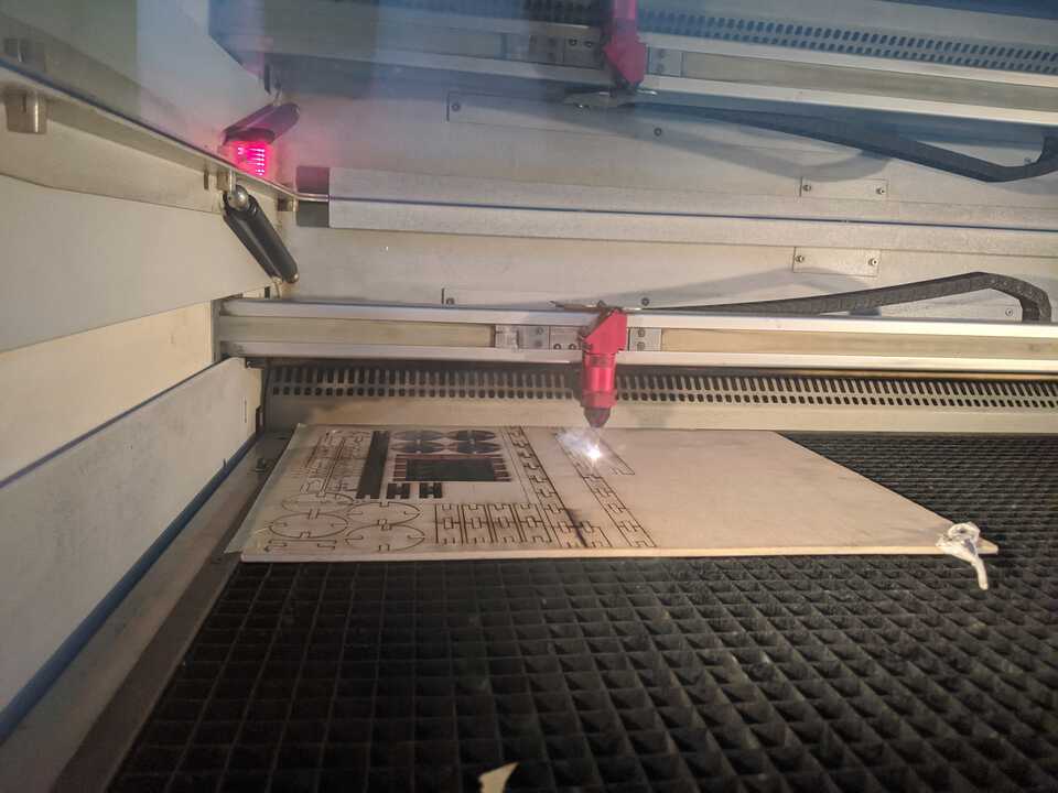
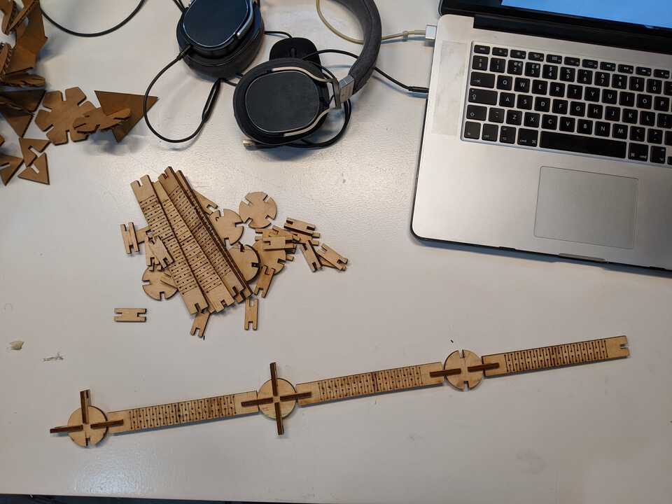
Assembling the piece
I started assembling the “bouncing ball”. It all fit together nicely. I didn’t print enough of them though… oops.
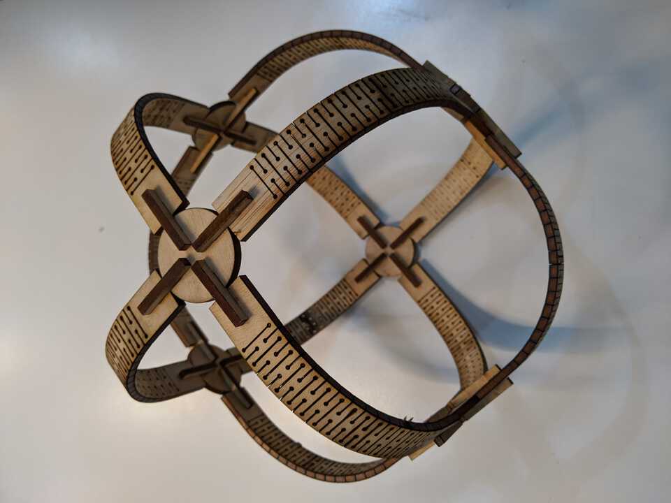
Final result: bouncing ball
All done and dusted!
Vinyl Cutting with Roland GX340
Setting up the machine
Cut some vinyl up

First I cut a piece of paper I thought would fit what I want to print. I am planning to print the logo of the company I work for, because I have no originality.
Insert into the machine

Insert the paper from behind the machine, while the little lever is up. Slide the paper in and lower the level to hold it in place. There are 3 different setting with the Roland GX340: Edge, Piece, or Roll. You have the definitions of what these means here. I used Piece as I have a small piece of vinly. That machine automatically rolls the piece in and out to measure it's size. Then Set the origin.
The little knife blade was already calibrated in the machine, but it's always safe to do a test to make sure it's all good, so let's do it. Press Test for a few seconds, the cutter will cut a little circle with a square in the middle.

On the computer go to the Roland GX-24 software, go to the Properties and in the Cutting Area click on thea Get from Machine button. That'll get the working area that we set in the machine by click on Piece.

Import your file as an Ai (exported as Adobe Illustrator 8, because the system is ancient), JPG or SVG. I used a JPG file, it appeared on the grid. We need to tell the software the path to cut, at the moment it is just an image.
Right-click > Image outline.

Click on Extract Contour Lines.

Group assignment: laser cutting and its secrets
Link to the group assignment page
Here it is: Tue's Group Assignment page.
Unfortunately many of the group assignments aren't group assignments, it's just a person doing it alone and sending you pictures... you don't have any say in what to do, not to do, to try, not to try, etc.
When you ARE in a group, everybody wants to have a say and nothing is done. I'm not a massive fan of these group assignments.
The laser cutter: Trotec Speedy 100
We used the Trotec Speedy 100 laser cutter. Arman found some file online to test the laser cutter with different font size, raster, cut, etc.

Some of my partners in crime.
Sending the file to JobControl from Rhinoceros
The file was opened in Rhino, and then sent to Job Control where we experimented with different settings for different materials (plywood and cardboard).
Sending the job from Rhino to JobControl
Ordering the jobs by color
How to use the machine...
First you have to make sure the extractor is switched on. Then you can switch the laser cutter on. Set the Z-axis with the very high piece of technology that is the mini-plastic or metal hammer
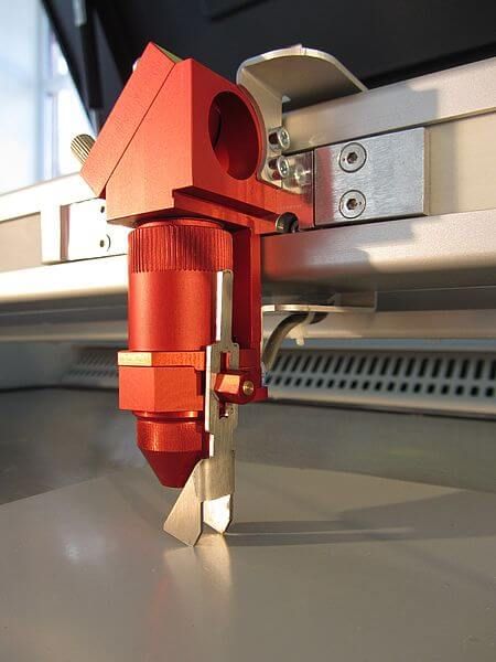
After making sure you have all the settings right in JobControl, simply execute the job.

The laser cutter doing what it does best: laser cutting
A video of that magic thing that is laser cutting. Hypnotising... unfortunately, because you'll be blind if you are staring at this mini-sun for hours.
The result, a beautiful piece of carboard
Here it's done. You can see it was burnt in the wheel, where it says 5%, when it should be pretty much blank... it puzzled us for 10-15 minutes, double-checking the settings, if we had the right raster option ticked, etc... until we noticed it was simple: the file we downloaded from the internet was wrong. The pure black (100% raster), was actually on the 5%, and therefore 0% was at 10%... ok, good!


The back of it. You can see in the some places it didn't actually cut completely through, which is weird because it has the same settings for the entire file... why?
Good question... why?