4. Computer controlled cutting
HIghlights of the week

1.Machines handled this week to learn Computer Aided Cutting:
A. Laser Cutter
B. Vinyl Cutter
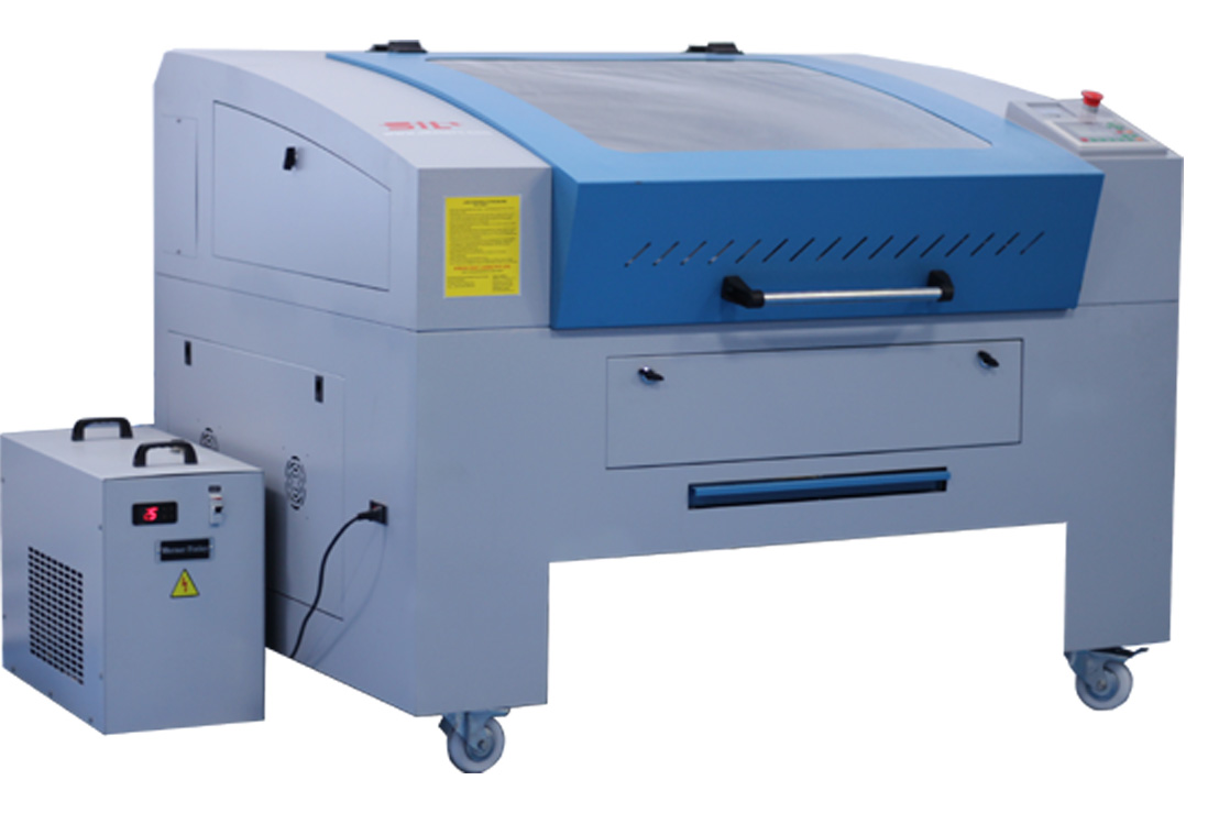
A1.SIL Laser Cutter at Vigyan Ashram & it’s parts:
a. Stabilizer-Gives a continuous voltage output of 230V to the delicate parts of the machine ahead.It cuts off high and low volatge thus preventing the supply of irregular volatge to the machine.
b. Isolation Transformer- it is also a kind of stablizer to ensure constant 230V output even during bad earthing of the lab.
c. UPS- is a battery backup device which allows us to use the machine even during power cut off. The UPS installed here gives 30 minutes backup and power 2.5KVA.
d. Chiller- The laser tube gets heated during operation. The coolant in the chiller absorbs the heat of the glass tube.
e. Compressor-During the operation continous air flow is mainatined along with laser which keeps the flame fine and prevents material from burning.
f. Invertor- The device basically functions in the absence of power which is very common here.
g. Exhaust-It collects the gases evolved during the operation and throws them outside maintaining the atmosphere around.
h. Machine body- Sturdy body with facility to move the transparent cover which allows place, move ourmaterial and keep a watch on the operations.
i. Software-RDWorks is the software used to send files to the machine. The file name is reflected in the display of the machine.
A2.Precautions while using Laser Cutting machine:
- Keep a continuous eye on the machine during operations.It becomes easy to take action in case of any flare-ups.
- We shouldn’t use toxic,flammable materials for cutting in lase cutter.
- Laser cutters generate fumes from subtrate whchcan be toxic.Donot use it in case of fume exhaust system isn’t in proper condition.
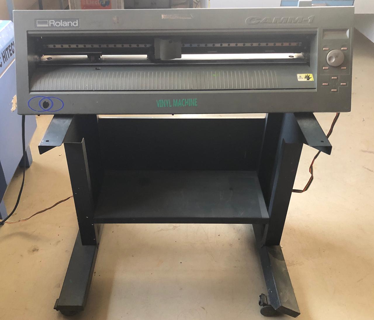
B1.Vinyl Cutter at Vigyan Ashram and it’s parts:
a.Cutting Blade: The small,pin-point,sharp blade cuts the vinyl sheet.
b.Roller:Adjust the roller between the frame we want our design to cut on Vinyl sheet.
c.operation lever: To adjust the vinyl sheet we can tighten and lossen the lever.
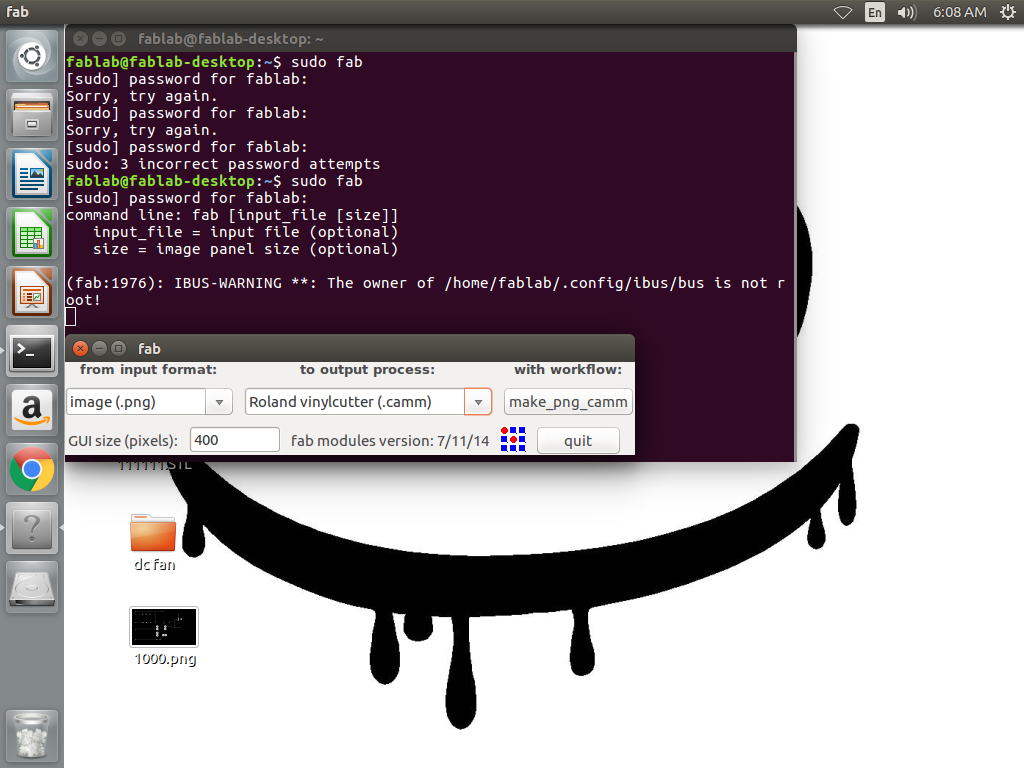
d.Software:Fab module is the software used to instruct command to vinyl cutter.
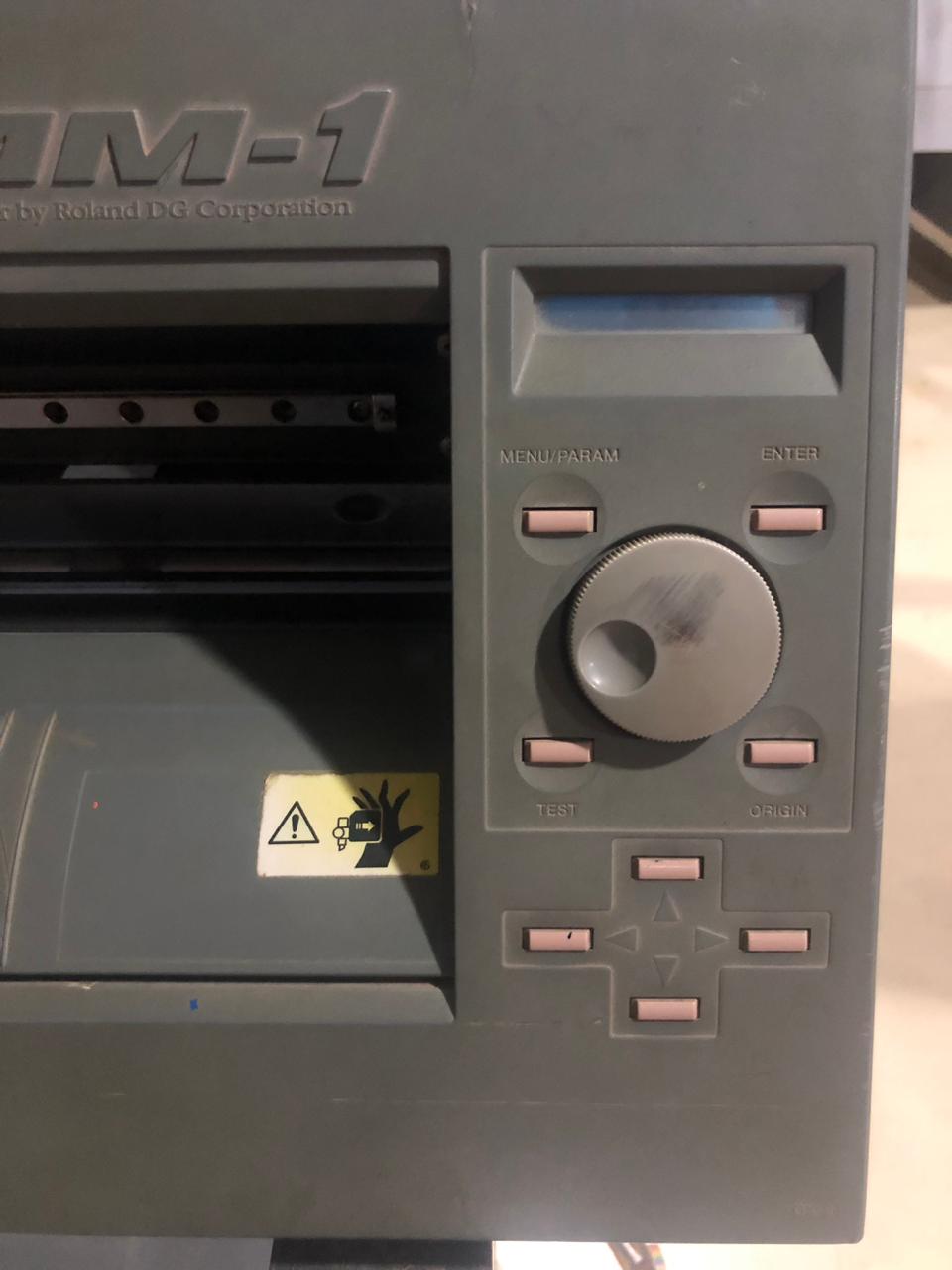
e.Display panel:Menu,Test,Enter,Origin and the operation being conducted is shown on the screen.
2.Group Assignment:
We worked in a group to characterize our lasercutter making test parts with different cutting settings of Power and Speed. Vaibhav and me worked to characterize the laser cutter for acrylic material.
A. Steps followed for measuring Kerf:
a. Designed in Rhino: Made squares of a fixed size 3cm*3cm with corresponding speed and power labled on them.
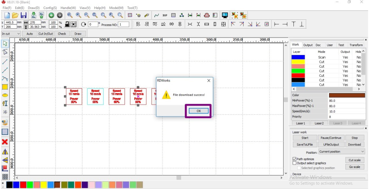
 b. Commands to machine by RDWorks: Made different layers for scanning and cutting. Mentioned command for power and speed for every square.
 c. Laser Cutter: Standardized the distance between the acrylic sheet and laser tip(z axis distance), origin and frame to cut the pieces.

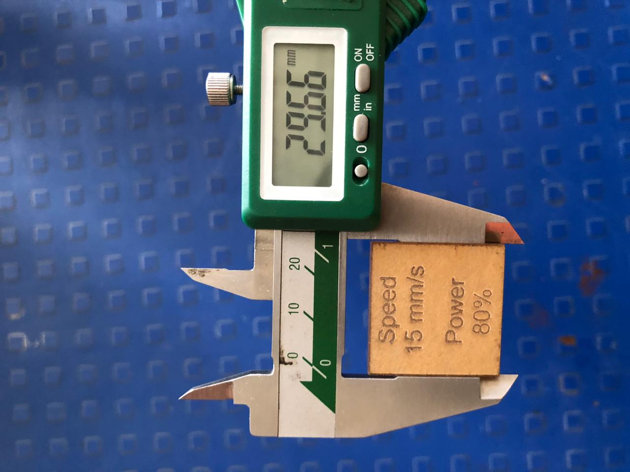
B.Calculations & Results:
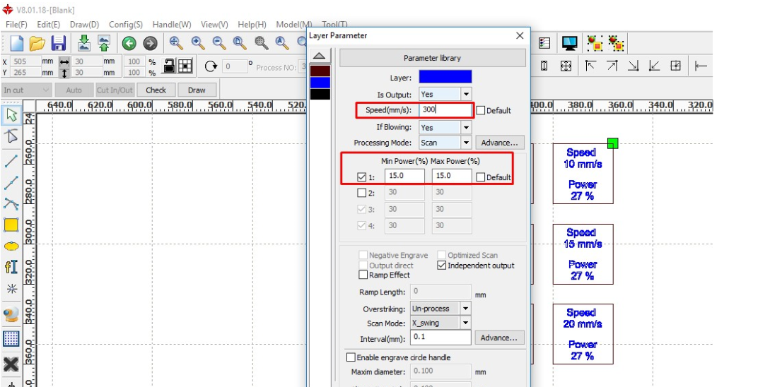
At constant speed of 10 mm/sec & varying power for cutting squares:
Note: Scanning speed is 300mm/sec and power 12%.
| Sr.No. | Power | Observation | Thickness(mm) | Standard Length(mm) | Kerf(mm) |
| 1 | 18% | Didn’t Cut | - | 30 | - |
| 2 | 21% | Didn’t Cut | -, | 30 | - |
| 3 | 24% | Didn’t Cut | - | 30 | - |
| 4 | 27% | Didn’t Cut | - | 30 | - |
| 5 | 30% | Cut | 29.73 | 30 | 0.27 |
| 6 | 35% | Cut | 29.69 | 30 | 0.31 |
| 7 | 40% | Cut | 29.64 | 30 | 0.36 |
| 8 | 50% | Cut | 29.68 | 30 | 0.32 |
| 9 | 55% | Cut | 29.66 | 30 | 0.34 |
| 10 | 60% | Cut | 29.57 | 30 | 0.43 |
| 11 | 65% | Cut | 29.65 | 30 | 0.35 |
| 12 | 75% | Cut | 29.69 | 30 | 0.31 |
| 14 | 80% | Cut | 29.60 | 30 | 0.40 |
At constant speed: 15 mm/sec:
Note: Scanning speed is 300mm/sec and power 15%.
| Sr.No. | Power | Observation | Thickness(mm) | Standard Length(mm) | Kerf(mm) |
| 1 | 18% | Didn’t Cut | - | 30 | - |
| 2 | 21% | Didn’t Cut | -, | 30 | - |
| 3 | 24% | Didn’t Cut | - | 30 | - |
| 4 | 27% | Didn’t Cut | - | 30 | - |
| 5 | 30% | Didn’t Cut | - | 30 | - |
| 6 | 35% | Didn’t Cut | - | 30 | - |
| 7 | 40% | Cut | 29.63 | 30 | 0.37 |
| 8 | 50% | Cut | 29.74 | 30 | 0.26 |
| 9 | 55% | Cut | 29.58 | 30 | 0.42 |
| 10 | 60% | Cut | 29.64 | 30 | 0.36 |
| 11 | 65% | Cut | 29.79 | 30 | 0.21 |
| 12 | 70% | Cut | 29.70 | 30 | 0.30 |
| 13 | 75% | Cut | 29.62 | 30 | 0.38 |
| 14 | 80% | Cut | 29.66 | 30 | 0.34 |
C. Conclusion:
1.The minimum Kerf keeping speed at 10mm/sec is at 30% power and at 15mm/sec is at 65% power for acrylic.Thus, characterizing the laser cutter.
2. Applying this data will will save power and cut acrylic precisely.
3. Minimum Kerf data will be useful for press-fit designs, adjusting Kerf values in slot thickness.
Download Kerf calculation files here..
3. Individual Assignment:
A. Cutting punchline on Vinyl Cutter.
B. Pressfit construction kit on laser cutter.
A1.Steps to Vinyl Cutter:
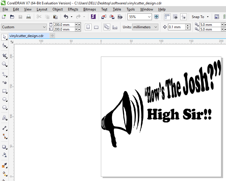
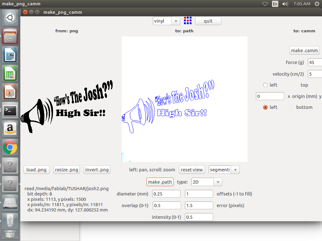
a.Designed in Corel Draw: Using an image of a speaker and adding punchline to it I made a design on Corel Draw. Measured the application and resized the image accordingly. Exported the image in png format.
b. Machine & Software:
b1:Inserted vinyl sheet on machine: The sheet on the machine covered the sensor.
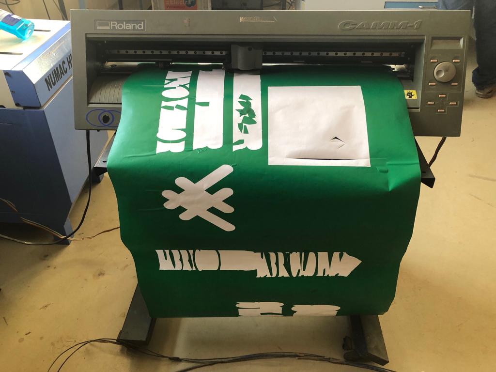
b2:Instructions from Fab Module software:uploaded the image in png format and elected the output in .camm format. Next, selected “Make Path” which showed the preview of my design.Last, selected make.camm and sent the file when machine was ready.
b3:Adjusted machine: It has basically 4 commands and 4 direction keys to move the sheet.Under “Menu”, selecting piece measures the length and breadth of the vinyl sheet. “Enter” key commands roller to move between the sensors. Set the “Origin” and checked the functinoning of blade with “Test” key.
b4:Operation: The blade moves with the outline of the design.
c. Sticking:Cut the part of the vinyl sheet which had design. Pasted masking tape on the design.Sticked the design on the laptop surface and removed it patiently using exacto.
Vinyl Cutter design file available here.
¶B1.Steps for Construction kit using cardboard:
Note: The carboard thickness is between 2.4 to 2.5 mm.
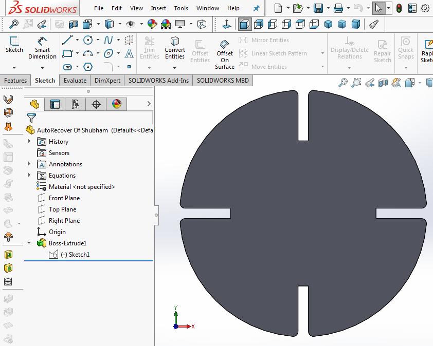
a. Designed in Solidworks: made 4 basic shpaes: circle,rectangle,hexagon,triangle.These files were saved in DXF format.
a1.Parametric Design: shapes are parametric based on width of slot,size of the shapes and the length of slot.
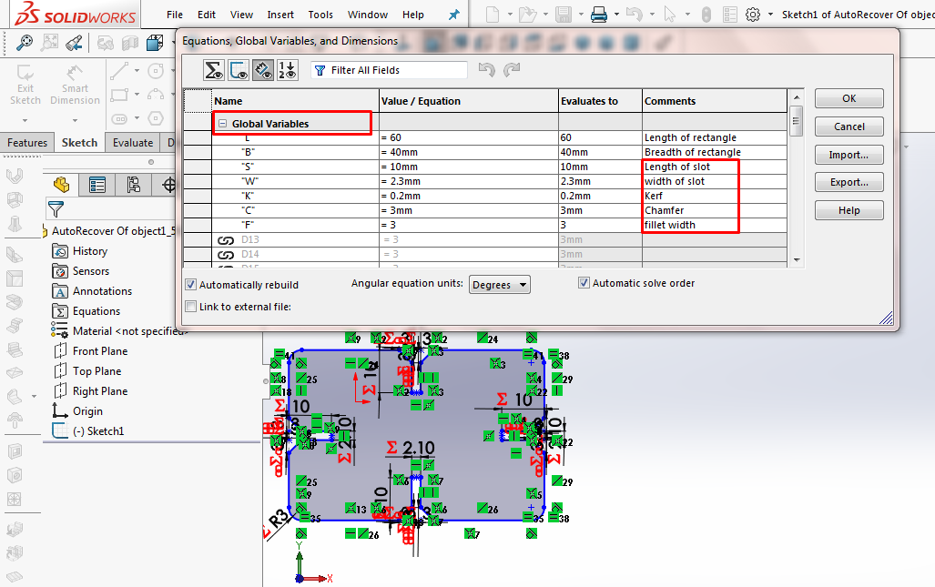
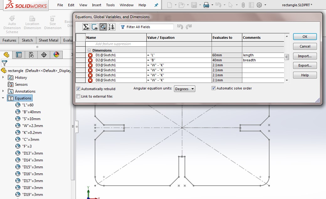
a2. Global Variables: In case of rectangle,
length=60mm
breadth=40mm
slot length=10mm
slot width=2.3mm
kerf=0.2mm
chamfer=3mm
fillet width=3mm
were defined as global variables.
a3.Kerf Value: 0.2 mm was subtracted from the width of all the slots being the Kerf value. This made the parts fix into one another. The data of Kerf for cardboard was taken from group assignment.
 a4. Relation of different dimensions with global variables: The sides of all the shapes are in proportion. The shapes should be handy to change dimensions on minimum changes which has been defined in parametric equations.
 a5. Parametric Equations: Values get calculated when the global variables are defined as parametric equations. In the comment section one can label the numeric values. This is an amazing feature where changng 1 global parameter can change the entire shape in proportion.
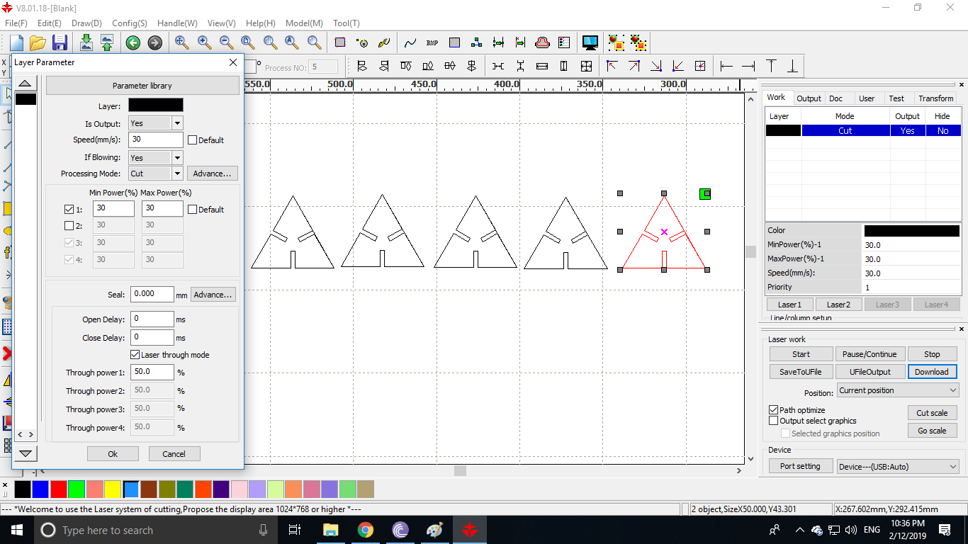
b.RDWorks to send commands:
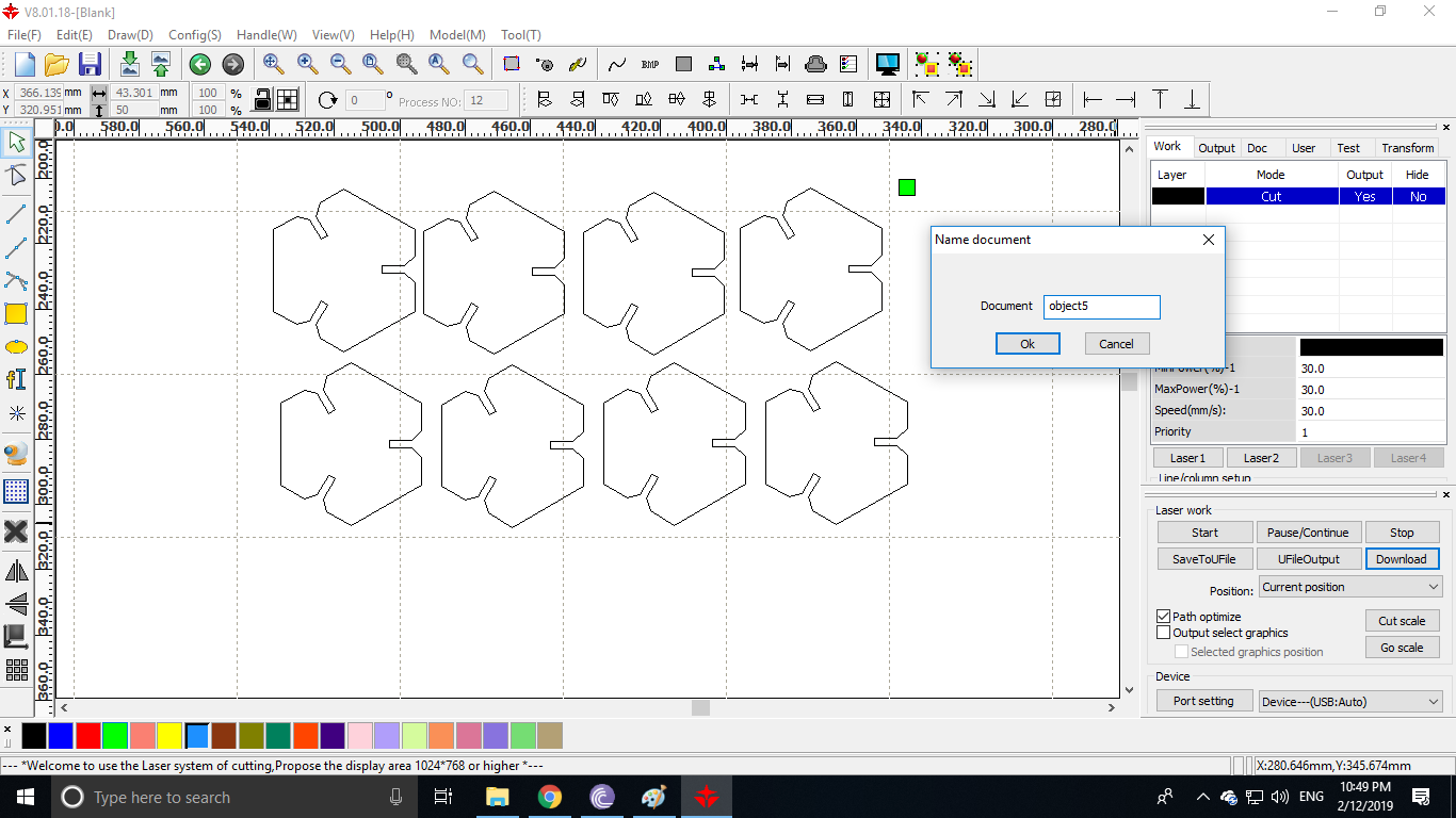
b1.Selected layer and gave values:Attributed values to power and speed such that Kerf is minimum. I have used max. and min. power=30%, speed=30%. For scanning we have to add different colour and values.
b2.File download:Named and downloaded the file which was reflected in the display of the machine.
 c.Operations:
c.1.Device turn on:The device was turned on in the fixed sequence of stablizer>isolation transformer>invertor>chiller>compressor>main switch>lamp>exhaust>laser.Was very careful while handling the machine.
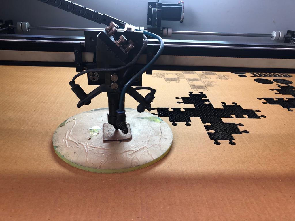
c2.Z-Axis distnace:The distance between carboard sheet and laser tip was adjusted to 7.5cm. This circular disc was used to mark the distance.
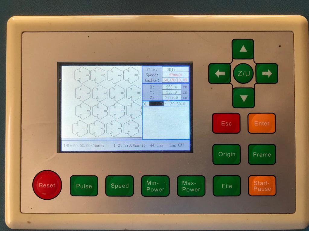
 c3.Display settings:This showed the design and power, speed values of my file. Set the “origin” and tested “frame” which gave me an approximation of the space of cardboard used. It has the function to select file, start/pause the operation, directions to move laser in all directions etc.
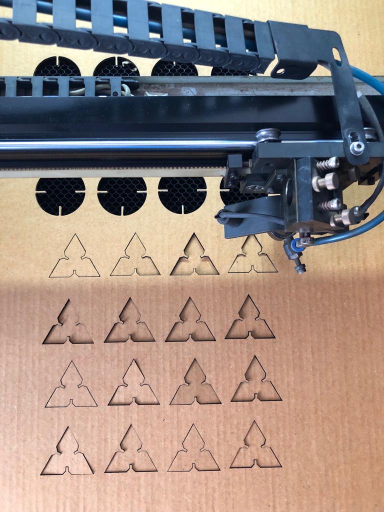
 c4.Laser cut:Finally it is a moment of delight to watch the design being cut by the laser. In the display setting we can check the part of design being cut. Waited for sometime after the opeartion so that the foul air in machine can be evacuated by the exhaust.
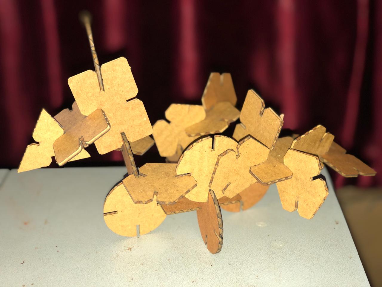
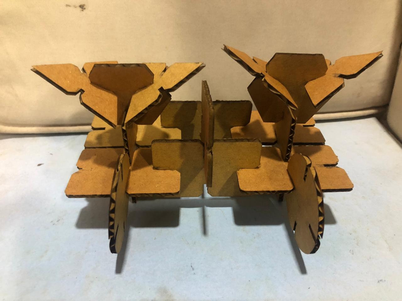
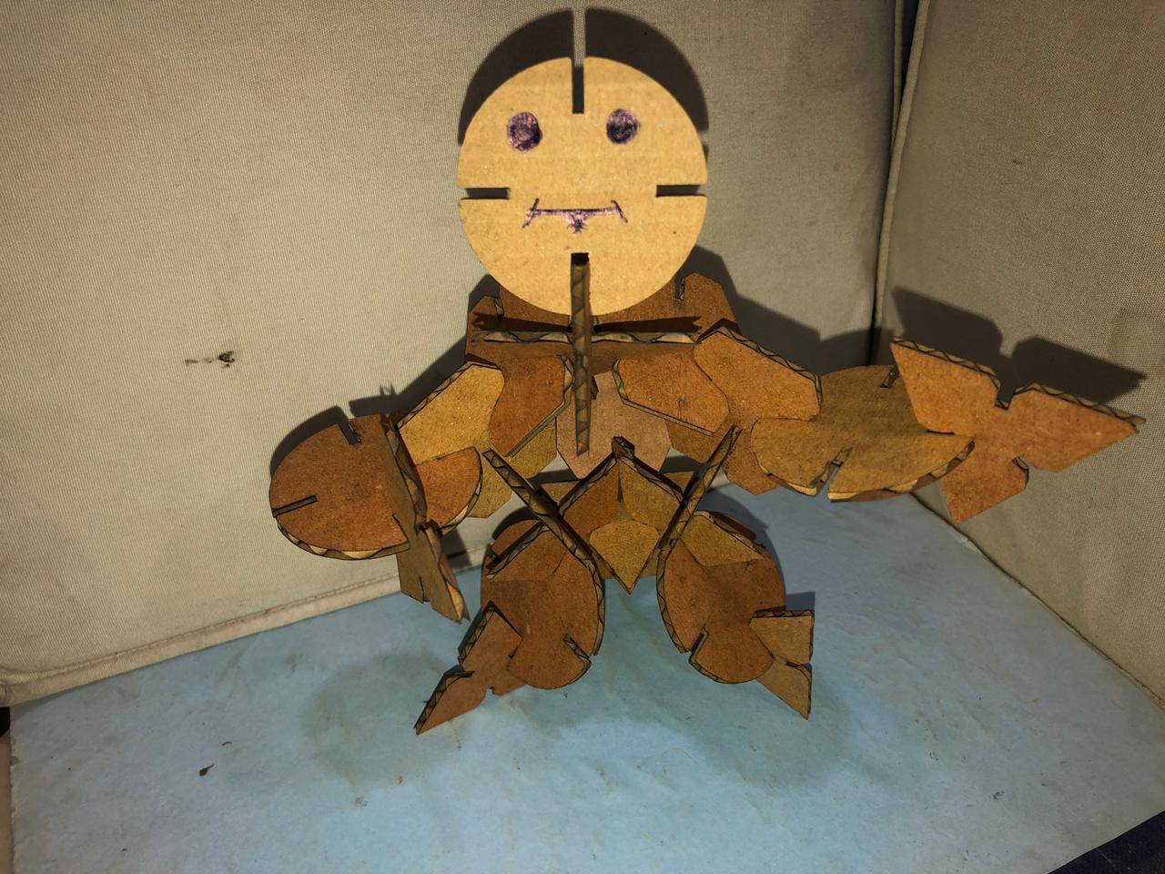
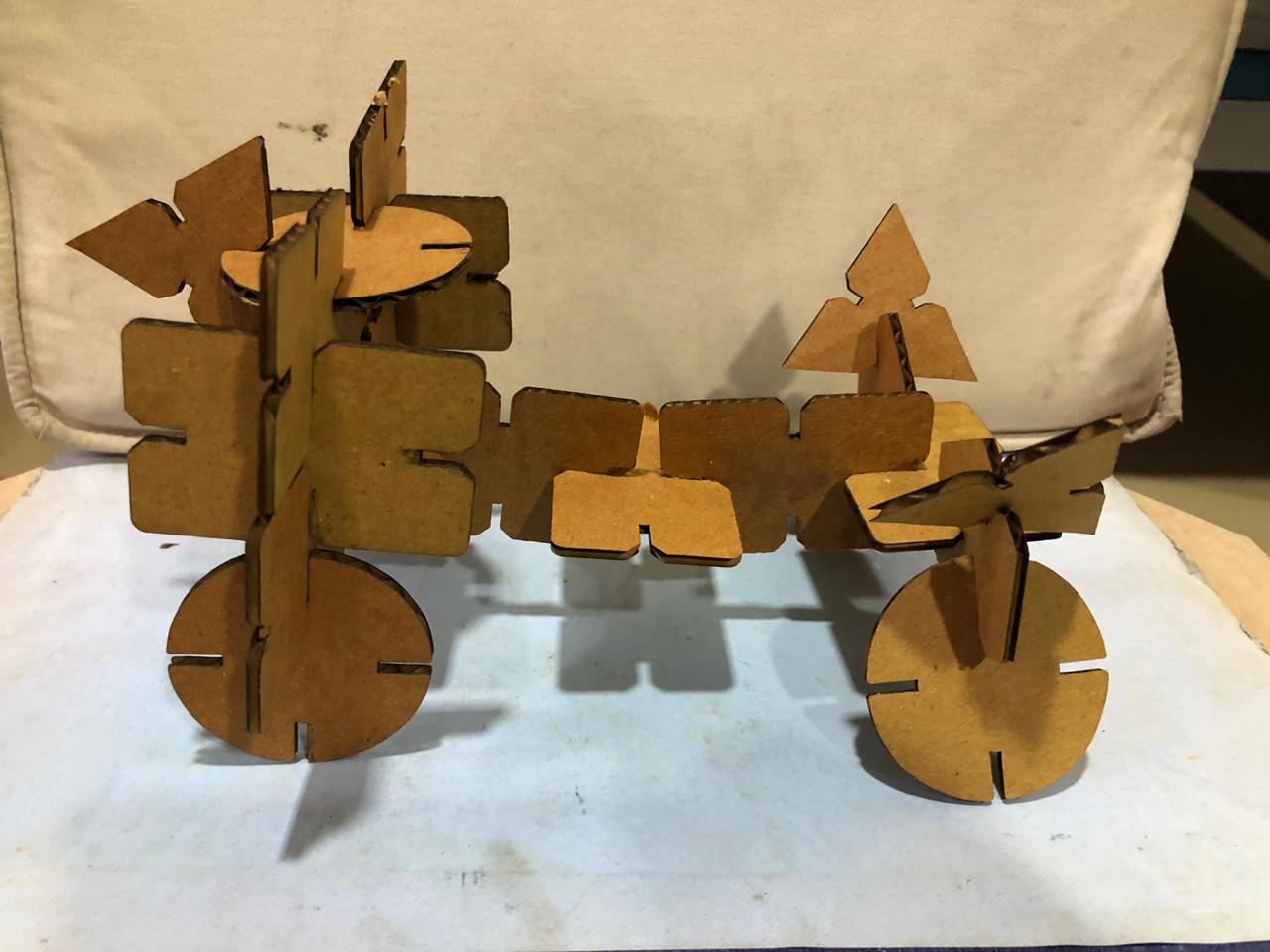
 d. Press-fit construction kit which can be assembled in multiple ways:The component which were cut were assembled and dissamebled in various ways. The parts interlocked
Laser Cutter design files available here.
5.Learning and Conclusion:
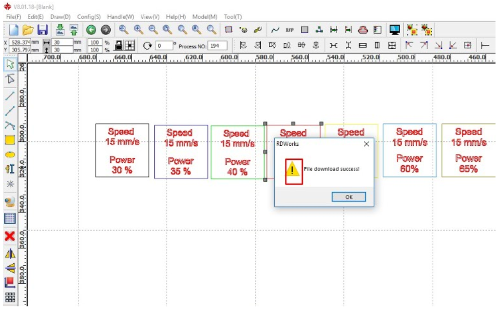
1. I personally didnot like the interface of RDworks.The choice of words at few places didnot make sense like engraving is named as scanning. On clicking a part of design the respective layer wasn’t highlighted and at places symbols created confusion. For example on successful downloading the file the symbol was:
 2. I personally enjoyed sticking Vinyl sheet onmy laptop. Removing vinyl sheet slowly needs patience but was fun. The left over of vinyl sheet can be used for screen printing.
3. It was difficult to make construction kit on carboard because the material isn’t uniform. The thickness varies and it’s not straight throughout.
4. I realsied the advantage of parametric drawing when adding “Kerf” once made the required changes in the entire design.
5. Making slots and interlocking pressfit depends on slot width and the length too. In the first design of rectangle I had kept the slot length small which didnot allow the parts to interlock perfectly.
2. I personally enjoyed sticking Vinyl sheet onmy laptop. Removing vinyl sheet slowly needs patience but was fun. The left over of vinyl sheet can be used for screen printing.
3. It was difficult to make construction kit on carboard because the material isn’t uniform. The thickness varies and it’s not straight throughout.
4. I realsied the advantage of parametric drawing when adding “Kerf” once made the required changes in the entire design.
5. Making slots and interlocking pressfit depends on slot width and the length too. In the first design of rectangle I had kept the slot length small which didnot allow the parts to interlock perfectly.